
Abstract
The deposition of platinum coatings by double glow plasma technique on titanium alloy substrates at different gas pressures is reported. The corrosion properties of platinum coatings were investigated. The coating deposited at gas pressures of 20 and 30 Pa had a preferred (220) orientation due to the initial nuclei with preferred growth on the surface of the substrate. The coating deposited at gas pressure of 25 Pa showed no evidence of preferential orientation. The platinum coatings showed better corrosion resistance than the titanium alloy. The electrochemical properties of the platinum coatings deposited at different gas pressures had some difference because the porosity in the coating increased with increasing gas pressure.
Introduction
Platinum is a stable, face centred cubic (fcc) metal with a high melting point of 1769°C, which is extensively utilised in a diversity of industrial applications due to its chemical inertness, high electrical conductivity, excellent corrosion resistance and catalytic activities.1, 2 For example, (i) Pt is used as a kind of jewellery; (ii) Pt is used in the manufacture of high quality glass and glass fibres; (iii) Pt is used as thermal and chemical protective coatings inside the tiny combustion chambers of satellite motors and other areas of space technology; (iv) one application of Pt is in catalyst gauzes for the manufacture of fertilisers, cyanides and plastics; and (v) Pt is widely used as a desirable electrode material. Owing to the high cost, the use of Pt as an electrode is limited. However, using Pt coated titanium (Ti) anodes is a good alternative to Pt bulk metal electrodes, and furthermore, Ti is regarded as a high corrosion resistance metal. At present, Pt coating can be prepared by many deposition techniques, including chemical vapour deposition (CVD),3 metal–organic CVD,4 sputtering,5, 6 pulsed laser deposition (PLD),7 electron beam evaporation,8 electroplating method9 or molten salt deposition.10 Sputtering is the preferred deposition method for the coating, which is used to produce films or coatings of pure metals, intermetallics and structural ceramics and is capable of obtaining coatings of desired stoichiometry. The PLD method could produce a dense Pt coating. For complex shaped substrates, the CVD technique appears to be an advantageous method to prepare Pt coating. Recently, the Pt coating by metal–organic CVD has attracted much interest. The quality of Pt coating depends mainly on the substrate temperature, deposition rate and suitable precursors. However, an intractable problem of adhesion is encountered due to a weak interaction between the Pt coating and the substrate. In previous work,11 a strong adherent Pt coating was obtained by double glow plasma technique. The adhesion of the Pt coating to the substrate was ∼60 N. Double glow plasma technique can be used for almost any solid metallic element for surface alloying to metallic substrates.12 The general advantages of this technique include low operating cost, low pollution, safer and more stable, high deposition rate, good coating uniformity, controllability of the coating thickness and strong adhesion to complex shaped substrates.13 Generally, the microstructure of the coating grown in the sputtering process was heavily dependent on the gas pressure and the substrate temperature.14 Furthermore, the structure of the coating could influence properties of the coating. In the present work, we will investigate the microstructure and electrochemical properties of the Pt coatings deposited by double glow plasma technique at different working gas pressures.
Experimental
A detailed description of the double glow plasma technique device was reported by Zhang et al.15 – 17 The surface alloying experiment was performed in a double glow plasma surface alloying device, in which a low temperature plasma was produced by a glow discharge process in a vacuum sputtering chamber. Three electrodes were designed in the chamber: one anode and two negatively charged members, the cathode where the workpiece was placed and the source electrode where the desired coating material was located. Both the cathode and the source electrode were surrounded by the glow discharges when the power was turned on. The first glow discharge heated the substrate to a high temperature, while the second glow struck the source electrode. The desired sputtering elements were sputtered by the second glow from the source electrode, travelling toward the substrate. Subsequently, the sputtering elements were deposited onto the surface of the substrates. In this work, the Pt plate was used as the target material. Some Ti alloy provided by Suzhou Fenggang Titanium Products and Equipment Manufacturing Co., Ltd (chemical composition of 55 wt-%Ti, 12 wt-%Al and 33 wt-%Nb) panels were used as substrates. The surfaces of the substrates were repolished by metallographic abrasive paper and then using 1 μm diamond media before deposition. Argon was used as working gas. The deposition conditions were: base pressure of 4×10⁻⁴ Pa, target bias voltage of −850 V, substrate bias voltage of −350 V, target–substrate spacing of 15 mm, holding time of 1 h and working gas pressures of 20, 25 and 30 Pa.
The microhardness of the Pt coating was measured by a Vickers hardness tester (HXS-1000A) with test force of 100 g. The microhardness of the specimen was repeated three times on each surface and then averaged. The crystal structure and orientation of the Pt coatings were investigated using X-ray diffraction (D8Advance, Bruker Co.). Before observation, the cross-sections of the Pt coated samples were eroded by 10 wt-% nitric acid (HNO3) for 23 s. The microstructure and morphology of the Pt coatings were observed by scanning electron microscopy (SEM, FEI Co., JSM-6360LV).
The electrochemical properties of the coatings deposited at gas pressures of 20, 25 and 30 Pa were studied by potentiodynamic polarisation test by means of a CHI660b electrochemical analyser (Shanghai, China). The specimen used as electrode was connected to a conducting wire and then covered with acrylic resin, leaving a square surface area of 1 cm2 exposed to the solution. The electrolyte was 3·5 wt-% NaCl aqueous solution open to air. A standard three-compartment cell was used with a saturated calomel electrode and a Pt electrode as reference and counter electrodes respectively. The potentiodynamic current potential curves were recorded at a sweep rate of 20 mV min−1. All the corrosion experiments were conducted at room temperature, and the potentiodynamic for every specimen was performed for one time.
Results and discussion
Figure 1 shows the X-ray diffraction patterns of the Pt coatings. The Pt coating was polycrystalline fcc structure. For Fig. 1a and c, the coating had a strong (220) peak and two weak (111) and (200) peaks. Figure 2 shows the measured intensity ratios RI = I220/I111 and RI = I200/I111 of the Pt coatings as a function of gas pressures. For gas pressures of 20 and 30 Pa, the Pt coatings showed a preferred (220) orientation due to the initial nuclei with preferred growth on the surface of the substrate. The nucleation process could play an important role in determining the distribution of orientations in the resulting coating. For a gas pressure of 25 Pa, no evidence for preferential orientation was found. In this study, the change of gas pressure affected the orientation of the Pt coating, which was in disagreement with the result reported by El Khakani et al.18 It can be inferred that the preferred orientation of the coating deposited by double glow plasma was controlled by gas pressure, which was dependent on the bombarding energy of the deposited energy particles. In general, the orientation of the Pt coating by sputtering or PLD is (111) planes. For (111), (100) and (220) planes of the fcc Pt,7 the surface energies γ(111), γ (100) and γ (220) are 1·07, 1·37 and 2·07 eV/atom respectively. The (111) orientation is typical for the growth of the fcc structure metals since it presents the lowest surface energy and the highest atomic density.4 The (220) oriented fcc Pt coating was rough with pinholes, which was similar to the microstructure of the (220) oriented Pt coating.19 In general, lots of pinholes were formed in the Pt coatings by sputtering or metal–organic CVD. The porosity of the coatings would be estimated by electrochemical properties of the Pt coatings.
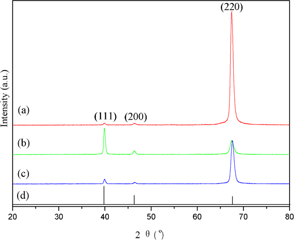
X-ray diffraction patterns of Pt coatings deposited at working gas pressures of a 20 Pa, b 25 Pa, c 30 Pa and d Pt powder standard
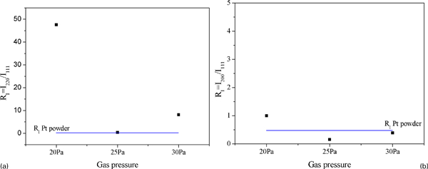
Measured intensity ratios a RI = I220/I111 and b RI = I200/I111 of Pt coating as function of gas pressures: horizontal lines indicate a RI = 0·23 and b RI = 0·45 for untextured powder samples:
For double glow plasma technique, the substrate temperature was influenced by gas pressure and substrate bias voltage.18 The microstructure of the Pt coating strongly depended on the substrate temperature, becoming coarser as the substrate temperature was increased.20 To further characterise the microstructure, the average grain size (D) for the coating was estimated using the Debye–Scherrer equation

Figure 3 shows the SEM images of the cross-section and surface of Pt coatings deposited at different gas pressures. The coating/substrate interface exhibited excellent adherence with no evidence of delamination and other defects. The cross-section of Ti alloy substrate showed some large holes because the substrate was severely eroded by acid. However, the cross-section of the Pt coating did not change. As shown in Fig. 3a–c, the thicknesses of the coatings were 2·90, 3·05 and 4·60 μm respectively, and the thickness was uniform. The thickness of the Pt coating increased with increasing gas pressure. However, it cannot be inferred that the increase in gas pressure resulted in a large deposition rate due to the pinholes in the coating. The defect volume in the coating had to be considered. The gas pressure relative to the deposition rate and the thickness of the film could influence the orientation of the Pt coating.21 Therefore, the orientation of the Pt coating should be of some difference when the coating was deposited by double glow plasma technique at different gas pressures. For Fig. 3d, the surface of the coating presented many fine strip shaped particles. With increasing gas pressure, the surface structure of the Pt coating evolved into square shaped grains together with many small grains interspersed among the large grains (Fig. 3e and f). It indicated that the crystal grains distinctly grew up with increasing gas pressure because Pt grains tended towards grain coarsening at high temperatures during the deposition process.22
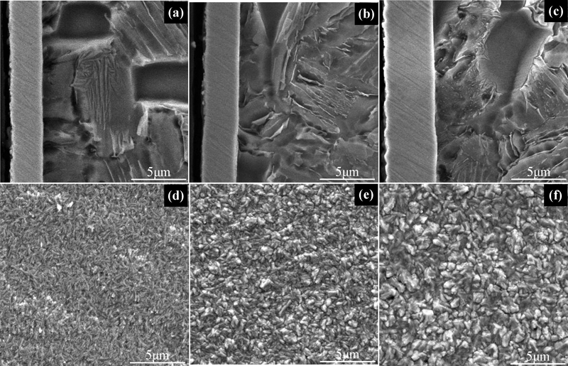
Images (SEM) of cross-section and surface of Pt coatings deposited at different gas pressures:
Figure 4 displays the microhardness of the Pt coatings. The microhardness value of the Ti alloy substrate was 380 HV0·1. It can be found that microhardness average values of the coatings were larger than that of the substrate. It indicated that the microhardness of the Pt coating decreased with increasing gas pressure owing to the increased crystal grain size. This result was compatible with that of the magnetron sputtered Pt films.20
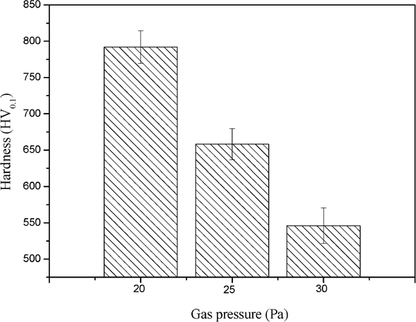
Microhardness of Pt coatings
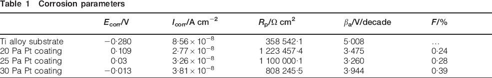
Figure 5 shows the polarisation curves of Ti alloy substrate and Pt coatings. The curves for the Pt coating had a relative low corrosion current density and more noble corrosion potential compared to the substrate. It can be inferred that the coatings could protect the substrate from corrosion to a certain extent. The corrosion potentials (Ecorr), polarisation resistance (Rp) and corrosion current densities (Icorr) calculated by the Tafel extrapolation method are shown in Table 1. The Icorr values for the coatings were smaller than that of the substrate, and simultaneously, the Rp values were larger than that of the substrate. It indicated that Pt coatings had a better corrosion resistance than the Ti alloy substrate. In comparison with the polarisation curves of Pt coatings (Fig. 5b–d), the corrosion potential of the Pt coating decreased with increasing gas pressure; however, the corrosion current density of the coating increased with increasing gas pressure (Table 1). These changes were attributed to the coating defects. Some defects such as pinholes, micropores, microchannels and microcracks in the coatings were almost impossible to totally avoid, which resulted in the decreasing corrosion protection effect of the coating. The amount of defects was crucial to the corrosion protection effect of the coating. The electrochemical method was used to analyse quantitatively the open pinholes. The porosity of the coating was calculated using the following equation23

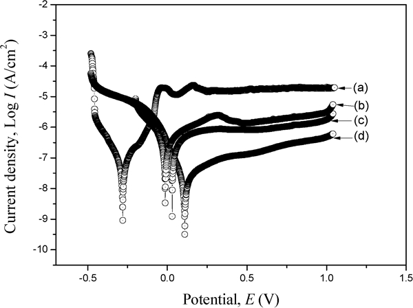
Polarisation curves of a Ti alloy and Pt coatings at working gas pressures of b 30 Pa, c 25 Pa and d 20 Pa
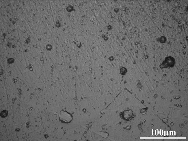
Optical micrograph of Pt coating at working gas pressure of 20 Pa after corrosion testing
Corrosion parameters
Conclusion
Uniform Pt coatings were obtained on Ti alloy substrates by double glow plasma technique at different gas pressures. For gas pressures of 20 and 30 Pa, the coating had a preferred (220) orientation due to the initial nuclei with preferred growth on the surface of the substrate. For gas pressure of 25 Pa, the coating showed no evidence for preferential orientation.
With the increase in gas pressure, the surface structure of the coating evolved into square shaped grains together with many small grains interspersed among the large grains. The microhardness of the coating decreased with increasing gas pressure owing to the increased crystal grain size.
The Pt coating had a better corrosion resistance than the Ti alloy substrate. The electrochemical properties of the Pt coatings were different because the porosity in the coating increased with increasing gas pressure.
Footnotes
Acknowledgements
This work has been supported by National Natural Science Foundation of China (50872055/E020703) and Funding for Outstanding Doctoral Dissertation in NUAA (grant no. BCXJ11-09) and Funding of Jiangsu Innovation Program for Graduate Education (grant no. CXLX11_0207). The authors would like to acknowledge Mr Boafo for refining the language.