
Abstract
Ni40·8Fe27·2B18Si10Nb4 (at-%) coating was deposited on mild steel substrate using high power diode laser cladding followed by laser remelting process. The phase composition and microstructures of the as cladded coating and remelted coating were analysed by X-ray diffraction, scanning electron microscopy and transmission electron microscopy. The microhardness and wear properties of the coatings were also tested and analysed. It was observed that the remelted coating has an amorphous matrix embedded with some dendrites. The remelting of the coating increased the hardness of as cladded coating by ∼25%. The remelted coating exhibited a characteristically lower friction coefficient (0·21) than the as cladded coating (0·27) and the substrate (0·31). Significant increase in wear resistance was found for the remelted coating compared with the as cladded coating and the substrate under identical conditions.
Introduction
Metallic glass alloys have been attractive advanced materials not only for fundamental studies but also for potential applications.1 Fe, Ni and Fe–Ni (or Ni–Fe) based bulk metallic glasses (BMGs) are of special interest among metal based BMGs due to their excellent mechanical and physical properties, such as high yield strength, good soft magnetic properties, high thermal stability and good corrosion resistance, and at the same time abundant natural resources and low material cost.2 – 4 In industrial fields, however, the application of these BMGs as engineering materials is restricted because of the limited size, low toughness at room temperature and high cost. In order to widen the industrial application fields, a composite amorphous material by coating techniques is preferred since the applications would not be limited by the size and brittleness of the BMGs. From the earlier investigations, it is clear that the coated amorphous layer exhibits better corrosion resistance than that for SUS 304 plate, higher Vickers hardness than that for hard chromium plating plate and better wear resistance than those for hard chromium plating plate and CrN coating plate.1, 5
The coating techniques could be arc spraying,6 plasma spraying5, 7 and laser assisted methods.8 – 13 Laser assisted method uses a concentrated laser beam as the heat source, and it melts the substrate that the feed stock is being applied to. This results in a metallurgical bond that has superior bond strength over thermal spraying methods. Additionally, the resulting coating is denser with no voids or porosity than that using other methods. Therefore, studies on the formation and fundamental properties of amorphous surface layers have been carried out using the laser assisted method. However, some coatings were made using high cost and easily oxidised metallic powders, and the laser process was performed in a shielding box where high purity argon gas was continuously supplied to provide an inert environment.8, 9 Some others just use the laser to melt the preplaced powders on the substrate surface10 and even to remelt the ingots of metallic glass compositions prepared by arc melting.11, 12 These limitations confined their practical applications in industrial fields. In addition, a high power diode laser (HPDL) can seldom be seen when producing such amorphous coatings.
In this study, high power diode coaxial laser cladding followed by laser remelting process was used to fabricate Ni–Fe based amorphous matrix coatings on a mild steel substrate. The microstructure and phase composition of the coatings were examined. For the mechanical properties, Vickers hardness was measured on the cross-section of the coating. The wear resistance of the coating was evaluated by sliding wear test with pin on disc method. The effect of the load variation on the wear resistance of the coating was also discussed.
Experimental
Gas atomised glass forming alloy powder with nominal composition (at-%) of Ni40·8Fe27·2B18Si10Nb4 having a particle size between 75 and 150 μm was used. Mild steel of 8 mm thick was used as substrate material. Before cladding, the powder was dried for half an hour at 150°C. An HPDL (Rofin DL035Q) equipped with a coaxial powder feeder was used to prepare the coating. The spot of the HPDL laser beam over the substrate was 3·3×2 mm. The process was divided into two sections. First, during the laser cladding process, the laser power was 1·7 kW, the scanning speed was 500 mm min−1 and the powder feeding rate was 18 g min−1. The cladding parameters were developed to obtain good clad formation with a height ∼1 mm as well as a low dilution rate to limit the composition change. Second, a high scanning speed of 8000 mm min−1 was used to remelt the coating under the power of 3·5 kW. The parameters could give a broad width and a deep depth of remelted layer and lead to a high cooling rate in the remelted layer. During the laser processing, a continuous flow of argon gas was maintained to prevent oxidation of the molten pool.
The microstructures of the coatings were characterised by a JEOL scanning electron microscope (SEM; JSM 6460) and a transmission electron microscope (TEM; Philips CM200) at 200 kV. The phase composition of the laser processed coating was analysed using X-ray diffraction (XRD; D/max2550VL/PC) with Cu Kα radiation at 20 kV between the 2θ range of 20 and 90°. Vickers microhardness measurements (HVS-10) were performed on the cross-section of the laser processed samples using a 500 g load and a holding time of 15 s, and an average value of five measurements is reported.
The sliding wear behaviour of the coatings was evaluated using a pin on disc tester under lubricated conditions. Distilled water was used as cooling medium and to obtain boundary lubrication conditions during all sliding tests. The substrate and as cladded and remelted specimens were cut into a cuboid with the size of 7×7×8 mm as pin. For the case of laser processing specimens, the top of the pin is the coating with a thickness of ∼1 mm. During the test, the rotating pin is put under a force load (100 and 200 N) against a stationary disc made of sintered Al2O3 ceramic with a hardness of 1800 HV. The rotational speed, wear track diameter and wear time are 400 rev min−1, 55 mm and 3600 s respectively. Three repeat tests were conducted for each test condition. An electronic balance (accuracy of 0·1 mg) was used for weighing the samples before and after the wear test to measure the weight loss. The weight loss was used as a measure of wear. The worn surfaces were examined under the SEM in the second electron mode to find out the wear mechanism.
Results and discussion
The microstructures of the coatings near the top surface in the as cladded and remelted conditions are shown in Fig. 1a and b respectively. The micrograph of the laser cladded coating without remelting mainly exhibits cells of nickel solid solution (Fig. 1a). It can be observed that the remelting of the laser cladded coatings produces mainly a fine dendrite structure and relatively dark matrix. Figure 2a presents the bright field TEM image and selected area diffraction pattern of the dark matrix in Fig. 1b. The bright field image shown in Fig. 2a reveals a typical amorphous matrix and some black nanosized crystalline phases embedded within the matrix. The featureless phase (region A) is the amorphous phase, and it is the selected area diffraction pattern, which consists of a halo ring typical of amorphous phase. The results indicate that the amorphous phase exists in the dark matrix substantially. The XRD pattern of the coating at a distance of ∼0·1 mm from the top surface is shown in Fig. 2c. A broad halo peak at diffraction angle of 43·8° (2θ) was obtained, which is typical characteristic of an amorphous phase; besides, the pattern also shows some sharp peaks. It can be concluded that both amorphous and crystalline phases are formed in the remelted layer. Based on the above structural and phase analyses, for the Ni–Fe–Si–B–Nb alloy system, it can be concluded that an amorphous matrix layer could be obtained using the HPDL cladding process followed by laser remelting. During the solidification after the remelting process, the grain growth was ceased, and then the remaining liquid was frozen into amorphous phase.
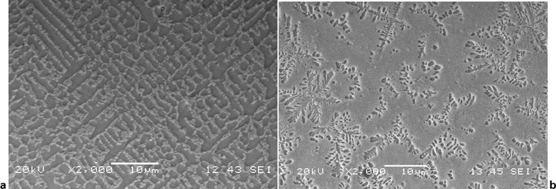
Microstructures of Ni–Fe–B–Si–Nb coatings in a as cladded and b remelted conditions
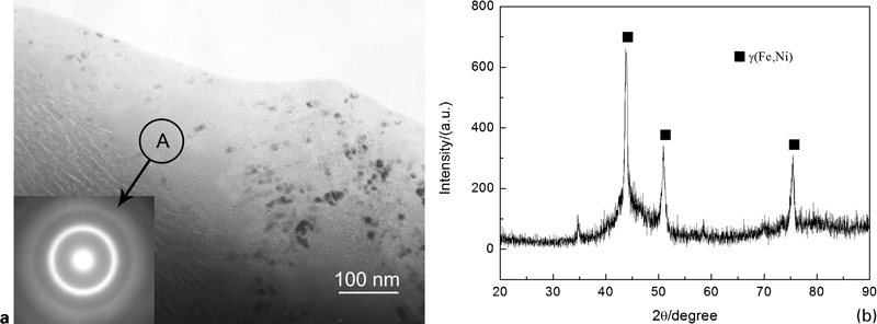
a TEM results of amorphous matrix and b XRD pattern of remelted coating
The variation in microhardness [HV(500 g)] as a function of distance (mm) from the top of the coating towards the coating/substrate interface is shown in Fig. 3. It can be observed that the microhardness, in general, increased with the increase in distance from the interface, and peak hardness occurs somewhere near the top surface of the coating. This may be due to the refined microstructure near the top surface of the coating, as the top surface initially subjected to high cooling rate after coating deposition as compared with other regions of the coating.14 It can also be seen that the remelting of the coatings also increases the hardness of the coating compared with that of the as cladded coatings. The maximum hardness was found to be 1128 HV(500 g). This may result from the formation of both the refined microstructure and the amorphous phase in the remelted layer, as shown by the TEM and XRD analyses.
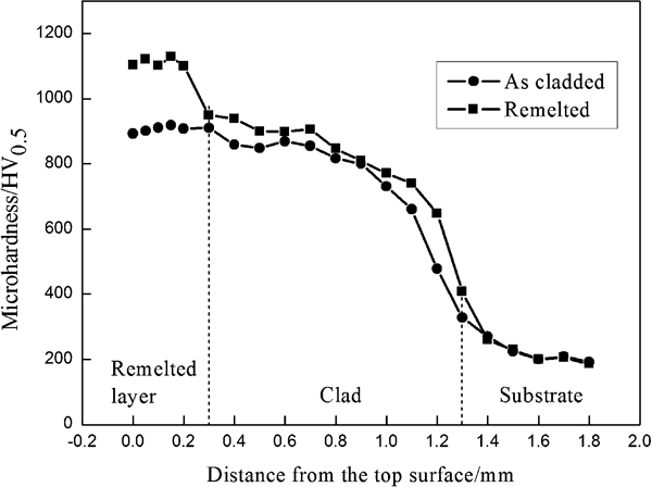
Microhardness versus distance from top surface to substrate for as cladded and remelted coatings
Figure 4 presents the friction curves for the substrate, as cladded and laser remelted coatings under wet sliding wear conditions. It can be observed that the remelted coating has a characteristically lower average friction coefficient (0·21) than the cladded coating (0·27) and the substrate (0·31). According to molecular kinetic and mechanical model theories of the frictional behaviour of elastomeric materials, the magnitude of the friction coefficient is inversely proportional to the hardness of the coating surfaces.15 The friction test results indicate that the formation of the amorphous phase in the coatings can effectively decrease the surface friction coefficient and consequently improve the surface friction resistances for the coatings. It can also be seen that the friction coefficient of the remelted coating is relatively more stable than that of the substrate and the as cladded coating. This may due to the high microhardness of the remelted coating; the worn surface could not be obviously changed during the sliding wear tests.
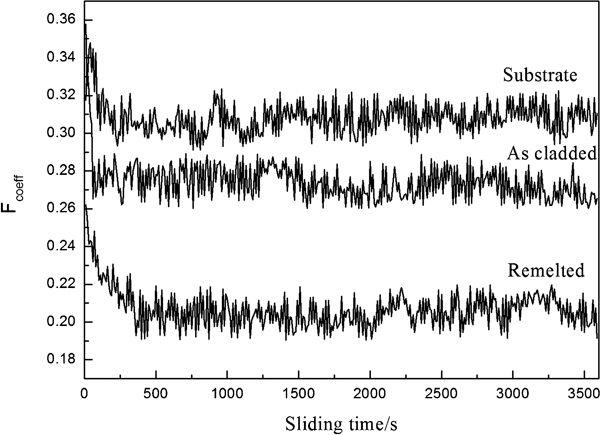
Friction coefficient versus sliding time for substrate, as cladded and remelted coatings
Figure 5 gives the wear mass losses of the substrate, as cladded and remelted coatings as a function of the applied loads. It can be observed that, in general, the wear losses of all the specimens increase with the increase in applied loads. It is apparent that the remelted coating exhibits an excellent wear resistance, which is inversely proportional to wear weight loss and is approximately three and six times lower than that of the as cladded coating and substrate respectively.
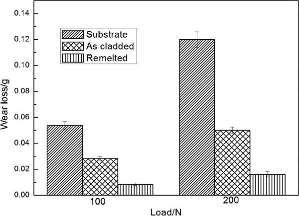
Wear weight loss versus applied load for substrate, as cladded and remelted coatings
For two-body abrasive wear, Rabinowicz16 proposes that volume loss was related to material hardness and sliding parameters, as shown in the following equation

The SEM images of worn surfaces of specimens of as cladded coating and remelted coatings subjected to sliding wear test at 100 N normal load were analysed to study the material removal mechanisms (Fig. 6). The worn surface morphology indicates that the major wear mechanism is abrasion rather than adhesion or delamination. For the substrate (Fig. 6a), wear tests led to deep grooves on the coating surface, which formed as the hard disc's surface digs into the sliding specimen's surface and then plow out the materials from the groove to the side. On the contrary, the as cladded and laser remelted coatings only suffered relatively mild abrasive wear. These wear tracks were characterised by the lack of deep grooves (Fig. 6b and c). The worn surface of as cladded coating is relatively rough with the presence of distinct grooves and craters. In contrast, the wear track of the remelted coating shows a rather smooth surface, as shown in Fig. 6c. Therefore, it can be explained why the remelted coating shows a dramatic decrease in wear loss, as shown in Fig. 5. In this work, distilled water was used as lubricant. Under lubricated conditions, the situation is very different from the situation under dry wear conditions. The immersion of rubbed surfaces in the water prevents oxidation and reduces the increase in temperature of the surfaces in the wear tests. Accordingly, oxide films are difficult to form, and delamination wear does not occur at low friction. In wear tests, the water cools the rubbed surfaces, ensuring that the energy provided by rubbing is less than the activation energy of the metastable phase transformation in situ.17, 18 Thus, plastic deformation is constrained under water lubricated conditions, preventing severe wear.
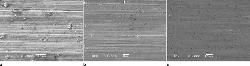
Scanning electron microscopy of worn surface morphology at applied load of 100 N:
Conclusion
The following conclusions can be drawn from the present study.
Ni40·8Fe27·2B18Si10Nb4 amorphous matrix coating was fabricated using HPDL cladding followed by laser remelting process. A featureless amorphous matrix region embedded with nanosized crystals was confirmed by TEM. Broad halo peak and diffraction peaks in the XRD pattern were found in the remelted coating.
The remelted coating reveals the highest microhardness of 1128 HV(500 g) due to the formation of amorphous phase.
The remelted coating has a characteristically lower friction coefficient (0·21) than the cladded coating (0·27) and the substrate (0·31). The wear mass loss of the substrate and laser cladded coating is six and three times that of the remelted coating respectively. Microploughing and craters were the main material removal mechanisms in the coatings.
The worn surface morphology indicates that the major wear mechanism is abrasion rather than adhesion or delamination. The wear track of the remelted coating shows a rather smooth surface.
Footnotes
Acknowledgements
The authors would like to thank the financial support provided by the National Natural Science Foundation of China (grant no. 50971091) and the ministry of Science and Technology of the People's Republic of China (grant no. 2009DFB50350).