
Abstract
TiC reinforced Ni based coating on Ti–6Al–4V was produced by laser cladding using colloidal graphite powder and pure nickel powder. The microstructure was characterised by SEM, energy dispersive spectroscopy and X-ray diffraction. Microhardness and dry sliding wear properties were investigated, and the results showed that diffusion of the substrate atoms had caused significant in situ growth of TiC and solid solution strengthening in the coating. TiC was polyhedron and petaline shaped. After laser cladding, the microhardness profile presented novel changes with depth in the coating. The TiC reinforced Ni based coating had good wear resistance on ball on disc dry sliding wear testing. Abrasive wear was the main mechanism.
Introduction
The excellent mechanical properties of titanium alloy are regrettably not matched by surface hardness and wear resistance for applications in engineering, aeronautics and astronautics. Over the years, an intensive research effort has been devoted to overcome this shortcoming using surface engineering.1, 2 Laser surface modification is one of the important surface engineering technologies. It has been used extensively to adjust the chemical composition, microstructure, hardness, wear properties, corrosion properties and even colour of the surface layer.3 The main advantages of laser surface modification are characterised by high beam quality, no vacuum required, easily automated, applicable for non-contact and remote processing, metallurgical bonding and so on.
Verezub et al. summarised the various technological routes of laser surface technologies.4 In summary, laser cladding shares the same traits: the substrate is melted just for metallurgical bonding, and the modification effect is from top to bottom of the modification layer. A typical characteristic is that the hardness profile changes very little throughout the depth of the coating or decreases from top to bottom of the modification layer because of the influence of dilution by the substrate.5 – 8 However, how to change the adverse elements of dilution by the substrate so as to be advantageous has not been explored. For example, when the substrate was melted and dissolved into the coating, the coating was improved by solid solution strengthening and in situ synthesis reinforcement.
In this paper, experiments were designed to explore the above laser surface modification technology. Graphite powder and nickel powder were mixed to fabricate the TiC reinforced Ni based continuous gradient composite coating by laser cladding on a substrate of Ti–6Al–4V titanium alloy. The atoms of the substrate were dissolved into the laser cladding coating for solid solution strengthening and in situ growth of reinforcement.
Experimental
The substrate material was Ti–6Al–4V with dimensions of Φ50×10 mm. The substrate was cleaned ultrasonically several times in alternate baths of acetone and absolute ethyl alcohol. Colloidal graphite powder (−2000 mesh) and pure nickel powder (−200 mesh) were mixed by mechanical grinding. The mixing time was 24 h, and the atomic ratio of the mixture was 1∶10 (C/Ni). The mixture was evenly placed on the surface of the substrate materials and then cold pressed to a thickness of about 1·0–1·2 mm. The TiC reinforced Ni based coating was produced by a 5 kW continuous wave CO2 laser system with 0·35 overlapping ratio. The power of the laser beam was set at 2·0 kW, and the diameter of the laser beam was fixed at 4 mm. The laser beam scanning velocity was set at 5 mm s−1.
All specimens were prepared by electrospark cutting and etched with a solution of hydrofluoric acid after mechanical polishing. The crystalline structure of the TiC reinforced Ni based coating was identified with a Philips X'Pert PRO X-ray diffractometer using Cu Kα radiation (λ = 1·54 Å). The microstructure and chemical composition were analysed with a Hitachi S-3400 scanning electron microscope coupled to an EDAX Genesis X-ray energy dispersive spectrometer. The microhardness of the cross-section of the TiC reinforced Ni based coating was investigated with a Vickers hardness tester with a load of 2·94 N and a loading time of 15 s. Dry sliding wear resistance of the TiC reinforced Ni based coating was evaluated on a ball on disc dry sliding wear tester at room temperature. The tested surface of the TiC reinforced Ni based coating was polished with 600 grit sandpaper. The ball counterpart was an Al2O3 ceramic ball with a diameter of 3 mm. The test load applied to the surface of the TiC reinforced Ni based coating was 16·58 N, the sliding wear frequency was 5 Hz and the eccentric distance was 2 mm. The wear test lasted for 120 min, and the total sliding distance was 452 160 mm. Wear mass loss was measured using an AL204 type electronic analytical balance with an accuracy of 0·1 mg. The worn surface was observed with a VHX-600K metallographic microscope.
Results and discussion
Microstructure
Figure 1 shows the SEM images of powders both in their raw state and after 24 h mechanical grinding. It is clearly seen in Fig. 1a that the rice shaped nickel particles in Fig. 1b had been broken and distorted by mechanical grinding. There is no union of nickel particles or graphite particles in Fig. 1a during analysis by SEM and energy dispersive spectroscopy, which indicated that the nickel and graphite powders had been evenly mixed.
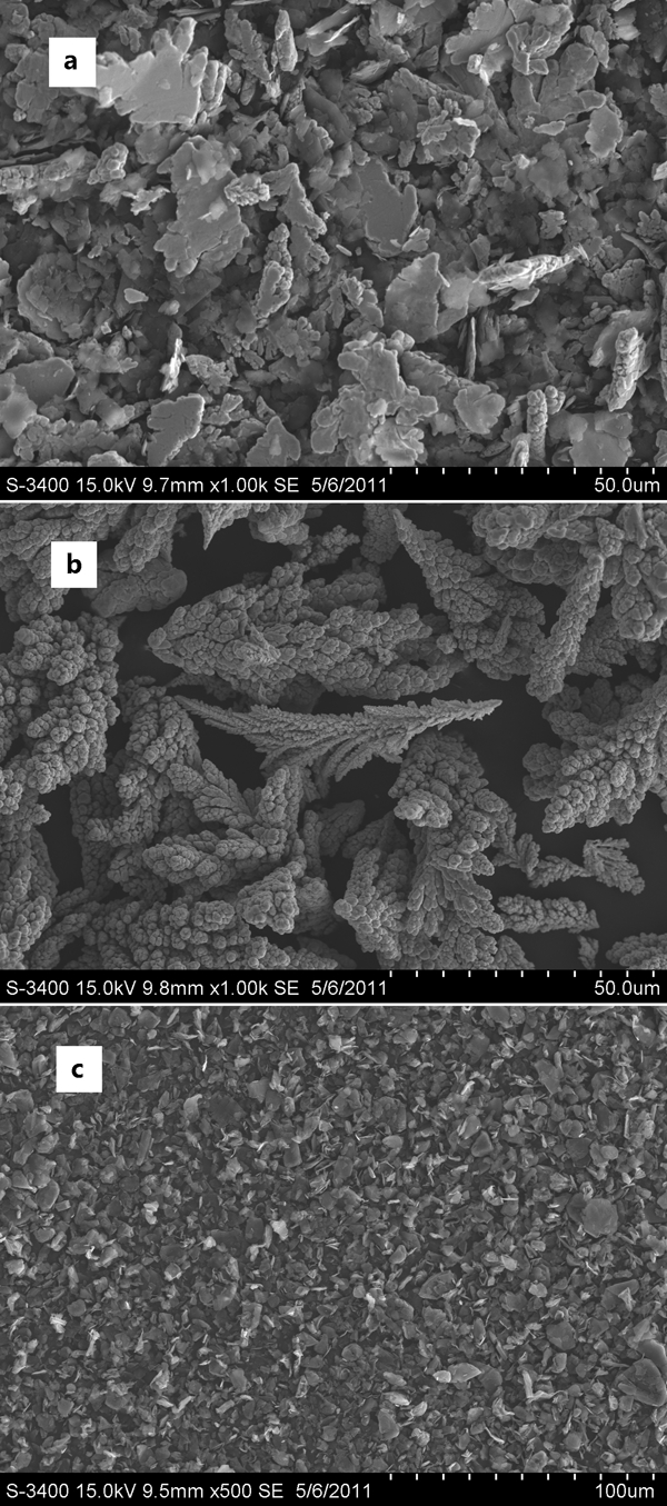
Images (SEM) of Ni+C powders for laser cladding:
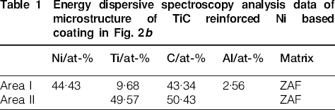
The TiC reinforced Ni based coating was produced by laser cladding using the mixture shown in Fig. 1. The surface and cross-sectional micrographs of the TiC reinforced Ni based coating are shown in Fig. 2. The chemical compositions of two different microstructures in Fig. 2, measured by energy dispersive spectroscopy, are listed in Table 1. This indicates that the reinforcement phase was TiC and the matrix was nickel based solid solution alloy. The solvent was titanium and aluminium atoms, which originated from the substrate. TiC was polyhedron or petaline shaped, and the particle size of the TiC was several micrometres up to 10 μm. It was a general conclusion that the shape of TiC was associated with the cooling velocity of the laser molten pool or the scanning rate.9 – 11 However, we found that the size of the TiC particles was close to the size of the graphite particles in Fig. 1c. Given that the dissolution of graphite depends on the formation of carbide, it could be concluded that the shape and distribution of TiC were closely connected to the size and distribution of graphite particles.
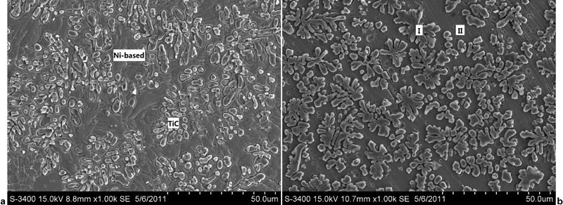
Images (SEM) of TiC reinforced Ni based coating produced by laser cladding:
Energy dispersive spectroscopy analysis data of microstructure of TiC reinforced Ni based coating in Fig. 2b
The crystalline phase of the coating surface was analysed as shown in Fig. 3. There was no new crystalline phase in the mixture before the laser cladding (Fig. 3), which meant that no clear alloying or chemical reaction occurred during mechanical grinding. However, it was clear that TiC and Ni were the only two crystalline phases in the TiC reinforced Ni based coating after laser cladding. Clearly, graphite had dissolved by chemical reaction and solid solution. In addition, the X-ray diffraction peak of Ni moved to a lower diffraction angle after laser cladding, which meant that the interplanar spacing increased because of the solution of titanium, aluminium or carbon atoms. The diffraction intensity of the Ni peak decreased significantly after laser cladding, which meant that the degree of crystallisation of the laser cladding coating decreased because of rapid solidification.
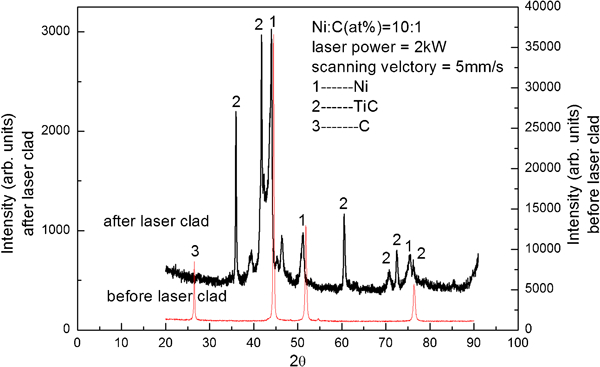
X-ray diffraction spectrum of TiC reinforced Ni based coating before and after laser cladding
Microhardness
The thickness of the TiC reinforced Ni based coating was ∼1 mm. The microhardness distribution with depth from the coating surface to the substrate in cross-section is shown in Fig. 4 and differs from the literature values.3 – 6 The highest microhardness on the surface of the TiC reinforced Ni based coating was 681·3 HV. The microhardness of the TiC reinforced Ni based coating dropped to its lowest value of 521·4 HV at 0·2 mm depth below the laser cladding coating surface. Then, the microhardness increased and reached its highest value of 839·9 HV at the base of the TiC reinforced Ni based coating. From there, the microhardness then fell dramatically to 300 HV at the heat affected zone within a distance of ∼0·2 mm. In addition, the thickness of the heat affected zone was ∼0·25 mm.
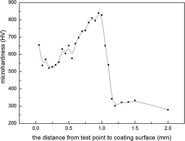
Microhardness profile with depth in TiC reinforced Ni based coating after laser cladding
The microhardness profile was influenced by the diffusion behaviour of atoms, which came from the substrate: this resulted in a solution strengthening effect with titanium and aluminium atoms dissolved in a nickel matrix. TiC, which grew by titanium atoms reacting with graphite, had a strong precipitation hardening effect. The change in microhardness distribution indicated that the base of the coating had more dissolved atoms than the surface of the coating.
Dry sliding wear resistance
Under the wear conditions in this study, the mean coefficient of friction of the TiC reinforced Ni based coating against the Al2O3 ceramic ball was 0·23, and its wear loss was 0·0010 g. In comparison, the morphologies of the worn surface of the original Ti–6Al–4V alloy and the laser cladding composite coating are shown in Fig. 5. Wear damage to the laser cladding coating can be seen in Fig. 5a and c, showing cutting, deformation and detached material that subsequently caused abrasive wear. The high hardness of the in situ particles of TiC provided good resistance to sliding wear, with particles below the surface resisting deformation caused by loads applied during the tests. The particles in the wear tracks generated were visible in relief compared with the surrounding matrix material, having resisted wear better due to their high hardness (Fig. 5c). The worn surface was covered with deep furrows parallel to the sliding direction, as shown in Fig. 5b and d. This is a typical feature associated with ploughing wear. The microhardness of the original Ti–6Al–4V alloy (278 HV) was lower than that of the Al2O3 counterpart. Hard asperities on the Al2O3 counterpart would easily penetrate into the surface of the original Ti–6Al–4V alloy, causing wear by removal of small fragments or ribbon-like strips of material.12 – 16
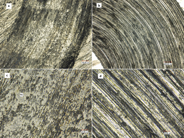
Optical micrographs of grinding mark:
Conclusion
TiC reinforced Ni based coating on Ti–6Al–4V was produced by laser cladding using colloidal graphite powder and pure nickel powder with a C/Ni ratio of 1∶10. Polyhedron and petaline shaped TiC grew by titanium atoms reacting with graphite in the laser melting pool. The shape and distribution of TiC were closely related to the size and distribution of graphite particles. The microhardness profile showed a novel change with depth in the laser cladding coating because of the precipitation hardening and solid solution strengthening effects caused by the diffusion behaviour of the substrate atoms. The TiC reinforced Ni based coating had good wear resistance on ball on disc dry sliding wear testing. Abrasive wear was the main mechanism.
Footnotes
Acknowledgements
This work was supported by the National Natural Science Foundation of China (grant no. 51002093), the Shanghai Science and Technology Development Foundation (grant no. 08QA14035), the Shanghai Leading Academic Discipline project (project no. J51402), the Special Foundation of the Shanghai Education Commission for Nano-Materials Research (grant no. 0852nm01400) and the Crucial Project of the Shanghai Science and Technology Commission (project no. 08520513400), China.