
Abstract
An amorphous layer was fabricated by laser alloying of the Ti–Al–TiB2–SiC–Y2O3 mixed powders on Ti–3Al–2V alloy in an open system. Results showed that a great number of the amorphous glassy phases were produced, which decreased the wear resistance of the alloying layer. It was found that the Mo addition decreased the glassy phase content and also refined the microstructure of the alloy layer, leading to the improvement of the wear resistance. This research provides essential theoretical and experimental basis to promote the application of laser alloying technology in the field of surface modification.
Introduction
Titanium and its alloys are extensively used in aeronautical, marine and chemical industries owing to their specific properties, such as high strength, excellent corrosion, oxidation and high temperature resistance. Nevertheless, the application of titanium alloys under severe wear and friction conditions is highly restricted due to their poor tribological properties, such as high friction coefficient and low hardness.1 Laser alloying is a promising technique for improving the wear, fatigue and corrosion resistance of machine titanium alloys.2 – 5
The addition of the rare earth oxide was beneficial in refining the microstructure and also in reducing the internal stress of the coating, which prevented the productions of the microcrack.6 However, too excessive rare earth oxide can form many inclusions.7 Therefore, in this study, 1 wt-%Y2O3 was added into the preplaced powders. Moreover, SiC is an advanced ceramic that has been developed recently, which demonstrates many good performances, such as corrosion and wear resistance. In this study, the SiC–TiB2 reinforced alloying layer was selected. It was found that the Y2O3 modified SiC–TiB2 reinforced alloying layer showed great brittleness and poor wear resistance. Through the repeated experiment, we found that Mo can be used to improve the microstructural performance of the laser alloying layer on titanium alloy. This paper will discuss the effect of Mo on the microstructural characteristics of the Y2O3 modified SiC–TiB2 reinforced laser alloying layers on titanium alloys.
Experimental
Laser alloying was performed on a CW ML-108 CO2 laser processing system. The Ti–3Al–2V samples had a size of 10×10×35 mm, and a 10×35 mm plane was used as the alloying plane. The preplaced alloying powders of Mo (⩾99·5% purity, 50–200 μm), Al (⩾99·5% purity, 50–200 μm), Ti (⩾98·5% purity, 150–250 μm), TiB2 (⩾99·5% purity, 50–150 μm), SiC (⩾99·5% purity, 50–150 μm, 25 wt-%Co) and Y2O3 (⩾99·5% purity, 1–30 μm) were used for laser alloying. Before the laser alloying process, the preplaced alloying powders should be mixed up until smooth, and the preplaced alloying powder layer with a depth of 0·7 mm was smeared on the substrate, and the water glass was used as binder. A continuous wave CO2 laser with a beam diameter of 4 mm was irradiated on the samples. The diameter of the laser beam was obviously less than that of the width of the samples, so four-track lap alloying layer was adopted in order to cover a whole alloying plane of the sample, and the lap rate was ∼30%. During the laser alloying process, the surface oxidation was prevented in a certain extent by argon with a flow rate of 40 L min−1. The parameters and the materials of the experiment are shown in Table 1.
Parameters and materials of laser cladding process in experiment
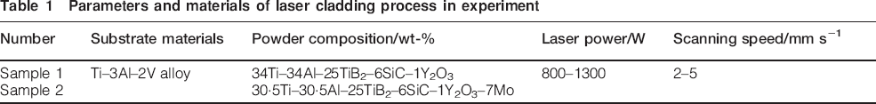
The wear resistance of the laser alloying layer was tested by an SFT-2M disc wear tester. An HV-1000 microsclerometer was used to test the microhardness distributions of the alloying layers. An SMX-1000/1000L X-ray diffractometer (XRD) was used to determinate the phase constituent of the alloying layers. The microstructural morphologies of the alloying layers were analysed by means of S-520 SEM, JEM-2010 high resolution TEM and energy dispersive spectrometer (EDS).
Results and discussion
XRD analysis
The XRD results indicated that there were Ti3Al, SiC, TiO2, Al2O3 and TiB2 in the alloying layer of sample 1 (Fig. 1). In fact, Ti and Al are activity elements, which reacted with oxygen in air during the alloying process, leading to the formations of TiO2 and Al2O3. The XRD result also indicated that Ti3Al can be produced through the in situ metallurgical reaction during the laser alloying process. Moreover, a large amount of Ti entered into the molten pool from the substrate due to the dilution effect, which further reacted with Al, leading to the formation of Ti3Al.
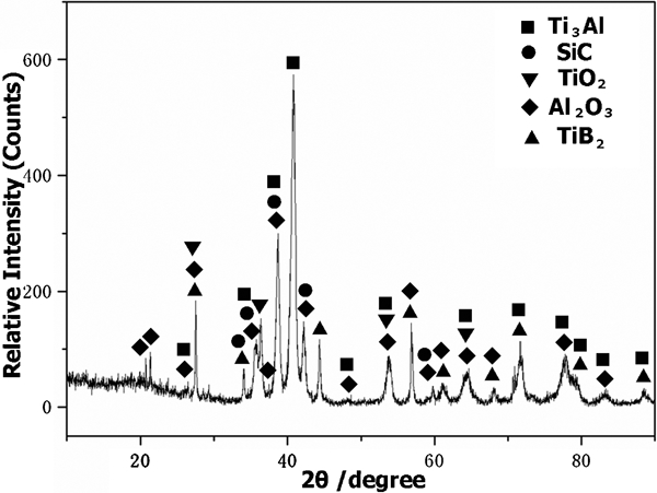
X-ray diffraction diagram of alloying layer in sample 1
SEM, TEM and HREM analysis
As shown in Fig. 2a, there was an excellent metallurgical combination between the alloying layer and the substrate in sample 1. The block shaped precipitates were produced, and the EDS/selected area diffraction pattern (SADP) test location was in the circle (Fig. 2b). Figure 2c shows the SADP of the block shaped precipitates, which indicated that the amorphous phases existed in this location. The EDS analysis indicated that there were C, O, Al, Si, Ti and Y in the block shaped precipitate (Fig. 2d). Combining EDS and XRD analysis, it was located that there were TiO2, Al2O3, SiO2, Al3V and a small amount of SiC in this location. Under the action of Y2O3, the SiO2–Al2O3–Y2O3 glassy phases were produced in the alloying layer.8 Thus, it was known that the block shaped precipitates were the amorphous glassy phases. The glass was hard to be corroded by the acids, so after the etching process, the glassy phases were present obviously in the alloying layer.
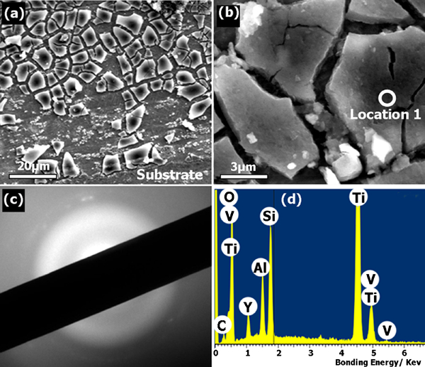
SEM images and test results of alloying layer in sample 1:
The stick shaped TiB precipitates were produced in the matrix of the alloying layer of sample 1, which may act as heterogeneous nucleation sites of the matrix phase (Fig. 3a). In fact, due to the dilution effect, the density of Ti in the bottom of the molten pool was high, which was favourable to the production of TiB. The HREM analysis result indicated that the TiB high resolution lattice phase was produced in the alloying layer of sample 1, which corresponded to its (101) crystal plane (Fig. 3b). The HREM image indicated that TiB showed a fine stick shaped morphology, and the width of TiB was only about several nanometres. The productions of TiB were beneficial in refining the microstructure of the alloying layer. There was also an excellent metallurgical combination between the alloying layer and the substrate in sample 2 (Fig. 4a). It was noted that a number of stick shaped precipitates were also produced in the bond zone of sample 2 (Fig. 4b).
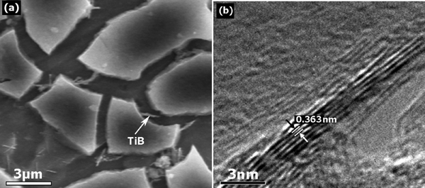
a SEM and b HREM morphologies of TiB in alloying layer of sample 1
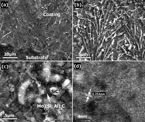
a–c SEM and d HREM morphologies of alloying layer in sample 2
It is suggested that during the alloying process, Al and Si atoms moved to Mo rich areas that form a ring decoration around the Mo rich core. The bright phases were SiC, and the dark phases were Mo5(Si,Al)3C (Fig. 4c). The presence of the retained phases in the structure was probably the result of incomplete decomposition of the Mo solid solution formed by mechanical alloying.9 The HREM analysis result indicated that the Mo5(Si,Al)3C high resolution lattice phase was produced in the alloying layer of sample 2, which corresponded to its (102) crystal plane (Fig. 4d). Mo5(Si,Al)3C showed fine particle morphologies, which was only about several nanometres. The production of Mo5(Si,Al)3C increased the wear resistance of the alloying layer.
Microhardness distributions and tribological properties
Under the actions of the phase constituent, the fine grain strengthening and the amorphous glassy phases, the microhardness of the laser alloying layer in sample 1 was in the range of 800–920 HV0·2, which was approximately three to four times higher than that of the Ti–3Al–2V substrate (∼260 HV0·2). The alloying layer in sample 2 was in the range of 1200–1300 HV0·2, which was significantly higher than that of the layer in sample 1 (Fig. 5). It was considered that the higher microhardness of the alloying layer in sample 2 was mainly ascribed to the finer microstructure and the action of Mo5(Si,Al)3C.
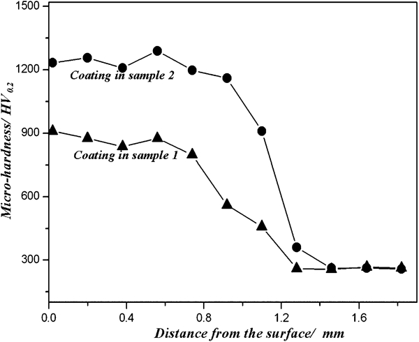
Microhardness distributions of alloying layers in samples 1 and 2
When the load was 54 N, the SEM images showed the worn surface of the alloying layer in sample 1 after the wear process (50 min). It was noted that serious adhesion patches and deep plowing grooves were present in the worn surface (Fig. 6a). In fact, a large number of amorphous glassy phases were produced, leading to a great brittleness of the alloying layer. Under the action of the counterpart, a portion of the alloying layer can be easily peeled off, leading to the formation of adhesion patches. However, due to the action of the high microhardness of the alloying layer in sample 2, the hard asperities on the surface of the counterpart were difficult to penetrate, leading to the improvement of wear resistance, which prevented the formations of adhesion patches and deep plowing grooves (Fig. 6b). Furthermore, under the dry sliding wear test, the moderate growth dispersal precipitates, such as titanium borides and Mo5(Si,Al)3C, may withstand the external normal load better.10 The wear volume loss of the Ti–3Al–2V substrate was approximately two or four times higher than that of the alloying layer in sample 1 or 2 respectively. The wear test results revealed that the wear volume loss of the alloying layer in sample 2 was approximately two times less than that of the alloying layer in sample 1 after 50 min wear time (Fig. 7).
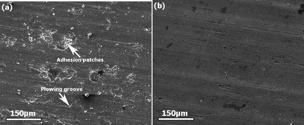
Worn morphologies of alloying layers in a sample 1 and b sample 2
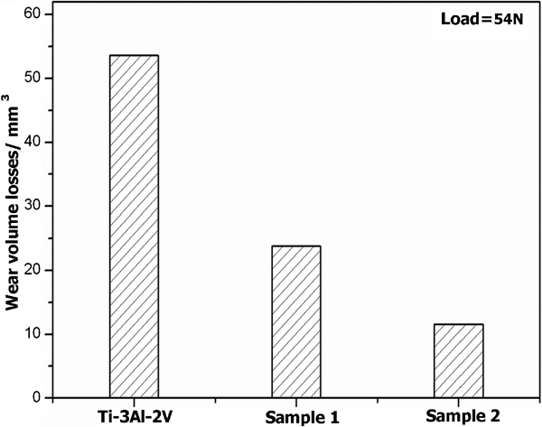
Wear volume losses of alloying layers in samples 1 and 2 and substrate
Conclusion
The correct choice of laser alloying parameters provides the Ti–Al–TiB2–SiC–Y2O3 laser alloying layer with microhardness distribution in the range of 800–920 HV0·2, which was approximately three to four times higher than that of the Ti–3Al–2V substrate (∼260 HV0·2). Y2O3 was beneficial in producing glassy phases among SiO2, Al2O3 and Y2O3, so too large quantity of amorphous glassy phases was produced, which decreased the wear resistance of the alloying layer. Mo addition was able to decrease the glassy phase content, which decreased the brittleness and also refined the microstructure of the alloying layer, leading to the improvement of the wear resistance. The wear volume loss of substrate was approximately four times higher than that of the Mo reinforced alloying layer.