
Abstract
A novel process with an environmentally friendly Zn transition layer was used in electroplating a Zn–Ni coating onto an AZ31 magnesium alloy, and direct current (dc) and pulse current (pc) electroplated Zn coatings were compared. The surface morphology, microstructure and macroresidual stress of the specimens were investigated using scanning electron microscope and X-ray diffraction spectrometry. The electrochemical method was adopted for corrosion resistance evaluation. The SEM images indicated that the Zn transition layer was necessary in electroplating a Zn–Ni coating. For the same electroplating time, the application of the pc plating mode was superior to the dc mode when producing a low residual stress, smooth, compact, nonporous and more corrosion resistant Zn transition layer. Moreover, the grain size of the pc plated Zn transition layers was finer than that of the dc plated layers. Most importantly, an electrodeposited Zn–Ni alloy coating on a magnesium alloy could be obtained successfully using a pc plated Zn transition layer.
Introduction
Magnesium alloys are among the most promising materials in biomedical, electronic, automobile and aerospace engineering industries on account of their low density, high specific strength, high thermal conductivity, good electromagnetic features and easy recovery.1, 2 Unfortunately, the application of magnesium alloys has been limited due to their poor corrosion resistance. Thus, surface modification is necessary to improve the corrosion resistance of magnesium alloys. Many technologies have been developed to form a protective coating on the surface of magnesium alloys including electroplating,3, 4 electroless plating,5 conversion coatings,6 gas phase deposition,7 laser surface cladding,8 anodising,9 microarc oxidation,10 etc. Among these, electroplating has received extensive attention, because it is a simple process of low cost with outstanding performance of coatings.
Among a large number of protective coatings, electroplated Zn–Ni coatings are likely to have superior anticorrosion properties, but so far, there have been very few studies on electroplated Zn–Ni coatings on magnesium alloys.11 This is because magnesium alloys are highly active in nature; thus, it is difficult to obtain a protective layer directly by electroplating. Magnesium alloys are prone to the rapid formation of a loose MgO and Mg(OH)2 film on the surface in air or water, which prevents the adhesion of the electroplating layer to the substrate.12, 13 Therefore, an appropriate pretreatment and transition layer are necessary in electroplating Zn–Ni coatings on magnesium alloys.
The most common transition layers used in the past (e.g. copper cyanide) are being stringently limited by environmental regulations for their harmful effects on human health and the environment. Huang et al. used copper sulphate to replace copper cyanide as the transition layer in electroplating.14 – 16 However, there is also a widely recognised principle in the electroplating industry that sulphate and chloride ions should not exist in the electroplating bath for preparing the transition layer on magnesium alloys. Being strongly corroded by the sulphate and chloride ions, the magnesium alloy cannot be covered completely by the transition layer, and there will be a large number of defects on the magnesium alloy surface. Many reports have proposed that electroless nickel, zinc or Zn–Cu could be plated on magnesium alloys and used as a transition layer for the subsequent process.11,17 – 20 However, few studies, to date, have been devoted to the microstructure and properties of transition layers in electroplating Zn–Ni coatings on magnesium alloys.
In this study, a Zn transition layer was electrodeposited on a magnesium alloy in an alkaline zincate bath without sulphate ions. Before electroplating the Zn transition layer, a simplified one-step pickling activation method was adopted. The effects of direct current (dc) and pulse current (pc) electroplating modes on the microstructure and corrosion resistance of Zn transition layers were compared. In addition, the feasibility of Zn transition layers used in electroplating the Zn–Ni alloy coating was simultaneously investigated.
Experimental
Preparation of coatings
Die cast AZ31B magnesium alloy (3·06Al–0·85Zn, wt-%) was used in this study. The samples of AZ31 were cut to dimensions of 25×40×0·6 mm.
The technological process of electroplating a Zn–Ni alloy coating followed the sequence ultrasonic cleaning→alkaline cleaning→one-step pickling activation→immersing in zinc solution→electroplating the Zn transition layer→electroplating the Zn–Ni alloy coating. The specific details are included in Table 1.
Technological process of electroplating Zn–Ni alloy coating
Analysis of microstructure
The morphology of the samples was observed with a scanning electron microscope (SEM; Hitachi S-570). The coatings were analysed by an X-ray diffraction spectrometer (XRD; Rigaku D/Max-3C, 40 kV, 30 mA) with Cu Kα
radiation at a scan rate of 2° min–1 to determine the phase composition and macroresidual stress. The size of crystal grains was calculated with the Scherrer equation

Corrosion resistance
The potentiodynamic polarisations were carried out on a CHI660B electrochemical analyser to evaluate the corrosion resistance of the Zn transition layers. The electrochemical measurements were conducted using a conventional three-electrode electrochemical system with a saturated calomel electrode (SCE) as the reference electrode, a Pt foil as the auxiliary electrode and the sample with an exposed area of 1 cm2 as the working electrode. The polarisation curves were measured starting from ∼300 mV more negative than the open circuit potential to more positive potentials, with a scanning rate of 1 mV s−1.
Results and discussion
Directly electroplating Zn–Ni coating after zinc immersion
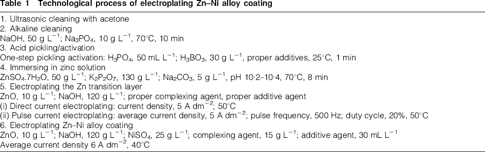
Figure 1a shows the surface morphology of the zinc immersion layer on the magnesium alloy after one-step pickling activation. As shown, the magnesium alloy cannot be fully covered, and there are a large number of pores. This indicates that additional treatment is essential to improve its corrosion resistance further. Figure 1b and c shows the surface morphologies of directly electroplating Zn–Ni coatings for 5 and 20 min respectively after zinc immersion. As can be seen, after directly electroplating the Zn–Ni coating for 5 min, the zinc immersion layer begins to be corroded, and obvious pores emerge. With prolonging the plating time to 20 min, the corrosion phenomenon is aggravated, and the surface demonstrates a network-like structure with broad pores. It is seen that if there is no transition layer, it is impossible to prepare an effective Zn–Ni coating directly after zinc immersion, that is, the surface transition layer plays a crucial role in electroplating a Zn–Ni coating on magnesium alloy.
Surface morphologies of directly electroplated Zn–Ni coatings after zinc immersion:
Electroplated Zn transition layers
Surface morphologies of Zn transition layers
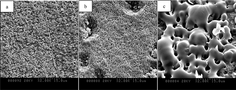
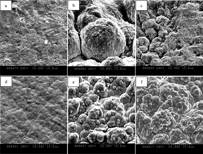
Figure 2a–c shows SEM images of dc plated Zn transition layers, and Fig. 2d–f shows SEM images of pc plated Zn transition layers for different electroplating times. As can be seen, for dc electroplating, in the first 3 min (Fig. 2a), the Zn transition layer exhibits a surface morphology with pin-like crystallites. The layer can cover the entire substrate, but the deposits are not compact and have many pores. Moreover, prolonging the electroplating time (Fig. 2b–c) still fails to produce a compact, non-porous layer on the surface. For pc electrodeposition, in the first 3 min (Fig. 2d), the Zn transition layer exhibits a tumour-like morphology, completely different from the morphologies seen in Fig. 2a–c. In addition, the boundaries of the tumour-like particles become blurry, implying that a compacted layer is formed during pc plating. When prolonging the plating time to 5 and 20 min, the layers become more compact and non-porous.
Surface morphologies of dc and pc plated Zn transition layers for different electrodeposition times:
These results are probably due to the lower macroresidual stress of pc plated Zn transition layers compared with that of dc layers, and the values of the macroresidual stress are measured and listed in Table 2. All of the electroplated Zn transition layers show compressive stress; however, blisters or falls may occur with excessive compressive stress. It can be seen from the data that the macroresidual stress decreases with increasing thickness of the layers. As the thicknesses of the layers are similar, the macroresidual stress of the pc plated Zn transition layers is lower than that of the dc layers. In the electroplating process, an overly large residual stress plays an active role in dislocation formation and movement in the growing coatings, and then plastic deformation may occur during deposition. Finally, the residual stress induced deformation leads to the formation of many obvious micropores in the dc plated Zn layers. However, for pc electroplating, the pulse interval is helpful in releasing the residual stress in the layers; thus, the number of pores decreases. This is consistent with the results of Hadian and Gabe, who showed that the pc plating mode can reduce the residual stress in the coatings to a certain degree.21
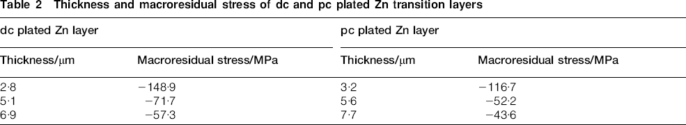
Thickness and macroresidual stress of dc and pc plated Zn transition layers
Phase composition of Zn transition layers
Figure 3 shows the XRD patterns for the dc and pc plated Zn transition layers. The dc and pc layers both exhibit a single phase of the Zn matrix with hexagonal primary crystal structure (reference PDF card no. 040831). The absolute values of intensity of the diffraction peaks corresponding to the (100), (101) and (110) planes are included in Table 3. It can be seen from Fig. 3 and Table 3 that the intensities of the diffraction peaks corresponding to the (100), (101) and (110) planes of the pc plated Zn coating are reduced significantly compared with the dc plated Zn transition layer, while the FWHM of the diffraction peaks is broadened for the (100) and (101) planes.
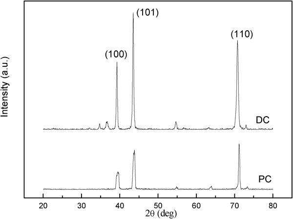
X-ray diffraction patterns of dc and pc plated Zn transition layers
Grain size of dc and pc plated Zn transition layers
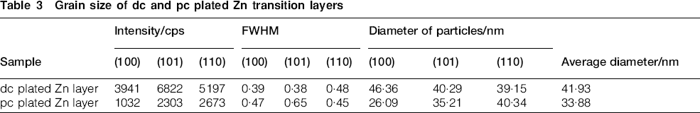
According to the FWHM of the peaks, the grain size of particles in the Zn transition layers is calculated with the Scherrer formula, and the results are included in Table 3. The average grain size in the pc plated Zn coating is smaller than that in the dc plated Zn coating. This can be explained by the different nucleation and growth rates of electrocrystallisation for the dc and pc electroplating processes. In the pc electrodeposition process, the pulse interval increases the cathode electrochemical polarisation but decreases the cathode concentration polarisation. Thus, the nucleation energy of the metal ions is decreased, and the nucleation rate is accelerated, resulting in the formation of more nucleates during the plating pulse and much finer grain size in the deposits.22 Thus, the grain size of the pc plated coating is smaller than that of the dc plated coating, which results in a more uniform and denser microstructure for the pc plated coating. This result is in accordance with the SEM images.
Corrosion resistance of Zn transition layers
Potentiodynamic polarisation curves of the bare magnesium alloys, dc and pc plated Zn transition layers are shown in Fig. 4. The thicknesses of dc and pc plated Zn transition layers are ∼5 μm. The AZ31 magnesium alloy substrate has the most active corrosion potential Ecorr value of around −1·5 V(SCE), whereas the dc and pc plated Zn transition layers have much nobler Ecorr values of −1·1 and −1 V(SCE) respectively. The corrosion current density Jcorr values for AZ31 magnesium alloy substrate is 5·27×10–3 A cm–2, whereas the Jcorr values for the dc and pc plated transition layers are 8·04×10–4 and 3·45×10–4 A cm–2 respectively. The Ecorr values of the dc and pc plated coatings are shifted in the noble direction by 400 and 500 mV respectively compared to the bare magnesium alloy, while the Jcorr values for the dc and pc plated samples are about 1/6 and 1/15 of the values of the bare magnesium alloy respectively. The corrosion rate of the three types of specimen is in the order: pc plated Zn coating<dc plated Zn coating<bare magnesium alloy. These results indicate that an electrodeposited Zn transition layer can improve the corrosion resistance of magnesium alloy, while the corrosion resistance of the pc plated Zn transition layer is superior to the dc layer.
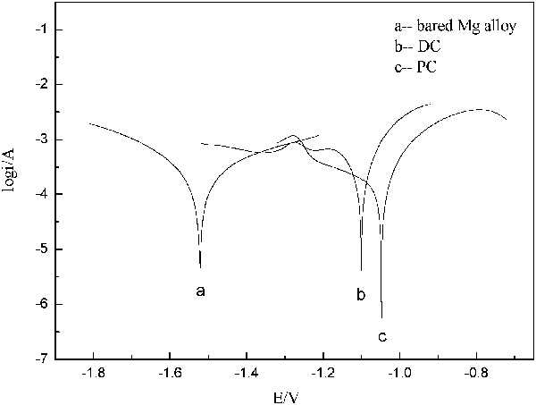
Potentiodynamic polarisation curves of dc and pc plated Zn transition layers in 3·5 wt-%NaCl solution
It is well known that the corrosive behaviour of metallic coatings is dependent upon their chemical composition, texture and morphology.23 When the coating is sufficiently dense, it can efficiently protect the substrate from corrosion by acting as a physical shield between the metal and the corrosive media. If the coating is not dense, its shielding effect will decrease significantly. From the analyses of SEM and XRD results, the surface of the pc plated Zn transition layer is denser, and its grain size is smaller than that of the dc plated layer, which shows that the pc is favourable for improving the corrosion resistance of electroplated Zn transition layers.
Electroplating Zn–Ni coatings on Zn transition layers
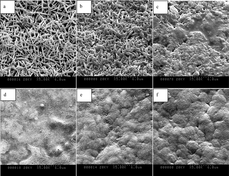
Zn–Ni alloy coatings were then electroplated onto the surface of the dc and pc plated Zn transition layers. Figure 5 shows the surface morphologies of the Zn–Ni alloy coatings. As can be seen from Fig. 5a–c, the electroplated Zn–Ni alloy coatings appear rougher, and the coverage seems poor when the dc plated Zn coating is used as the transition layer. To be more specific, after electroplating a Zn–Ni alloy coating for 5 min (Fig. 5b), the crystalline grains of the Zn–Ni coating are coarse and non-uniform. When prolonging the treatment time, the corroded appearance is aggravated. When the electrodeposition time is extended to 20 min (Fig. 5c), the Zn–Ni coating displays a porous structure, which cannot satisfy the high corrosion resistance demand of the coating. Therefore, the dc electroplated Zn coating is not suitable as a transition layer in electroplated Zn–Ni alloy coatings. Figure 5d–f shows the surface morphologies of Zn–Ni alloy coatings using a pc plated Zn transition layer. As can be seen, after electroplating a Zn–Ni alloy coating for 5 min, the coating is dense and there are very few pores on the surface (Fig. 5e). As the plating time increases to 20 min (Fig. 5f), the coating tends to be more compact, and there is no corroded appearance.
Surface morphologies of electroplated Zn–Ni coatings on surface of Zn transition layers prepared with different plating modes and times:
As the above results show, the surface morphologies of the Zn–Ni alloy coatings that have pc plated Zn as the transition layer are superior to those that have dc plated Zn as transition layer. This is because the pc plated Zn transition layer is more uniform, more compact and less porous than the dc plated Zn transition layer. In general, the pc electroplated Zn coating is more appropriate for use as a transition layer for subsequent electrodeposition on magnesium alloys.
Conclusion
A low cost and environmentally friendly electroplated Zn transition layer was successfully used in electroplating Zn–Ni alloy coatings on an AZ31 magnesium alloy. The Zn transition layers were deposited by dc and pc plating modes, and the structure, corrosion resistance and feasibility of electroplating subsequent Zn–Ni alloy coatings were analysed. The macroresidual stress of the pc plated Zn transition layers was lower than that of the dc plated Zn transition layers, and the pc plated Zn transition layer was more uniform, more compact and less porous. The application of pc plating also effectively refined the grain size of the Zn transition layer. As a result, the pc plated Zn coating had better corrosion resistance. In addition, the pc electroplated Zn coating was more appropriate for use as a transition layer in electroplating a Zn–Ni alloy coating on the magnesium alloy because the surface of the Zn–Ni alloy coatings using a pc plated Zn transition layer was compact, dense and pore free, while the surface using a dc plated Zn transition layer presented a severely corroded appearance.