
Abstract
ZrB2/Fe cladding layer was in situ synthesised by plasma transferred arc powder cladding on mild steel substrate using Zr and B4C as the precursor powders. The phase composition and microstructure were investigated by X-ray diffraction analysis, optical microscope, scanning electron microscopy and energy dispersive spectrum. Microhardness of the layer was examined at room temperature. The results show that the phases of the cladding layer are ZrB2 and iron. ZrB2 particles have three morphologies: acicular, short rod and block. Reaction process could be divided into four stages according to the state of reactants. ZrB2 particles gradient distribute in substrate from surface to bottom of the layer. Skeleton-like structure and cluster structure of ZrB2 are formed in the surface part, and particulate reinforced structure is formed in the middle and bottom part of the layer. The microhardness was greatly improved due to the presence of ZrB2 particles in comparison with the substrate.
Introduction
Metal matrix composites (MMCs) are recognised as candidates for wear resistance and high temperature oxidation resistance applications because of their exceptional hardness and high temperature stability. Among various ceramic particulates, because of the excellent combination of high mechanical, physical, thermal shock and oxidation resistance properties, zirconium diboride (ZrB2) ceramic is a material of particular interest especially being used as ultrahigh temperature ceramic (UHTC). It has been widely applied in many fields such as wear parts, cutting tools, nozzles and electrodes.1, 2
Same as TiB2 ceramic, ZrB2 is expected to be one of the best reinforcements for steel matrix.3 Addition of ZrB2 to Fe matrix is expected to demonstrate high mechanical strength similar to that of TiB2/Fe composite coating. TiB2 dispersion in Fe matrix has shown excellent mechanical strength, hardness and fracture toughness and impact resistance.4, 5 ZrB2 addition has advantage over TiB2, because it does not have many stable intermediate phases such as TiB2. However, the poor wetting behaviour between ZrB2 ceramic phase and Fe matrix makes it difficult for dense sintering.
Little attention has been devoted to ZrB2 particles reinforced MMCs. So far very few reports are available on ZrB2/Fe composites. Only some researchers synthesised ZrB2–ZrC/Fe composites coating by gas tungsten arc welding (GTAW). Among various surface engineering technologies, plasma transferred arc (PTA) cladding is more commonly used because of the high temperature, excellent arc stability, low thermal distortion of the part, high cladding speed and high energy exchanging efficiency.6 For this reason PTA cladding process is thought more suitable for the production of ZrB2.
The salient aim of present investigation is to develop an in situ synthesised ZrB2/Fe cladding layer on mild steel substrate by PTA powder cladding. It was expected that ZrB2 reinforcements would be formed through the in situ reaction between a preplaced precursor of Zr and B4C. PTA cladding process and microstructure of the ZrB2/Fe cladding layer were also studied in the paper.
Experimental procedure
Materials
The mild steel [composition: Fe–0·18C–1·32Mn–0·53Si (wt-%)] with dimensions 165×50×10 mm was chosen as the substrate. Before the PTA powder cladding, steel coupon was polished with 200 grit SiC abrasive paper and degreased in acetone. Zirconium (≥99·2 wt-%Zr, ≤0·07 wt-%FeCr), boron carbide powders (composition: ≥76 wt-%B, ≤2·0 wt-% dissociated C) are used as the precursor for PTA powder cladding. The powders were weighed in a desired molar ratio (Zr/B4C = 2∶1), according to the following reaction: 2Zr+B4C→2ZrB2+C. Reactants (73 wt-%Zr and 27 wt-%B4C) were thoroughly mixed in a stainless steel container using stainless steel balls for 20 min to ensure homogeneity. The combined powders were mixed with sodium silicate binder to form slurry and then preplaced on the surface of steel substrates. The thickness and width of the preplaced coatings were fixed to 2 mm in height and 16 mm in width respectively. The preplaced coatings were dried in shadow and cooled for 24 h and then heated to 573 K for 2 h before the surfacing process.
PTA powder cladding process
A PTA powder cladding equipment made in China was used in the coatings’ treatment. Argon was blown coaxial to protect the processing area during the PTA process. The PTA cladding parameters were: cladding current 140–180 A, cladding voltage 28–32 V, argon flowrate 8 L min−1, and cladding speed 72 mm min−1, torch swing frequency 0·667 Hz and swing width 16 mm, and temperature range of cladding procedure 300–7000 K.
Microanalysis
The samples for metallography investigations were sectioned perpendicular to the cladding direction using an abrasive cutting machine under water cooling condition. Microstructure examinations of the samples’ cross-section were carried out by using an Olympus GX51 optical microscope (OM) and a Hatchi S-4800 scanning electron microscope (SEM) equipped with a genesis energy dispersive X-ray spectrometer (EDS). Phase identification was carried out on a Rigaku D/MAX-2500 X-ray diffractometer (XRD) with Cu Kα radiation.
Microhardness
Microhardness measurement was performed by using a Leica VMHT002 microhardness tester with a load of 500 g applied for 10 s on the cladding layers’ cross-section along vertical and horizontal direction.
Result and discussion
Phase constituents
Figure 1 shows the XRD spectrum of the cladding layer. It reveals that phases in this composite coating are ZrB2 and Iron. ZrB2 particulates can be in situ synthesised by direct reaction of Zr and B4C. Zr in the welding pool all reacts with B synthesising ZrB2. No other boride product such as Fe2B and FeB is detected in Fig. 1. The absence of such brittle borides can improve the crack resistance of the cladding layer when the cladding layer undergoes serve stress.7 No peaks of carbides can be found in this spectrum, too. This indicates that the carbides ZrC and Fe3C are difficult to obtain in the cladding layer.
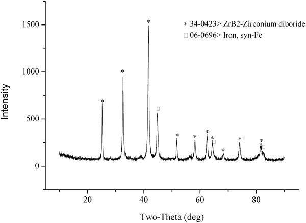
X-ray diffraction spectrums of ZrB2/Fe cladding layer
Figure 2 shows the EDS analysis of the cladding layer. Peaks of Zr and B are observed obviously in spectrum 1. Combined analysis of XRD spectrum, the authors can deduce that the acicular particle is ZrB2 that was in situ synthesised during the PTA powder cladding. Spectrum 2 shows the EDS result of substrate. Through the combined analysis of XRD, spectrum 2 and morphology of the phase, the authors also can identify the iron phase in region 2 as bainite.
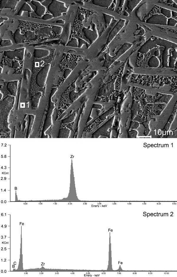
Energy dispersive spectroscopy analysis of ZrB2/Fe cladding layer
Reaction process of Zr–B4C system
Metallurgical process of reactants is very important for the microstructure and performance of MMCs, a lot of research work had been reported in this research field.8 According to the state of the reactants, the authors put forward four potential stages of this reaction process.
In the first stage reactants of Zr and B4C are all in solid state. The interaction between them is mainly occurred at their interface. The growth of the ZrB2 layer relies on the diffusion of Zr and B atoms. In the second stage reactant Zr (melting point 2128 K) is in liquid stage and B4C (melting point 3036 K) particle is still in solid state.9 B4C particles will float up to the surface part of the welding pool due to its low mass density (2·52 g cm−3).9 Reactions between Zr and B4C could be significantly promoted considering the higher concentration of liquid Zr. ZrB2 phases can be formed at the surface of solid B4C, which will in turn hinder the further interaction of Zr and B4C. In this stage a great number of Fe will fuse and then participate in the Zr–B4C metallurgical process. The dilution rate of the cladding layer should be controlled to an appropriately rate to eliminate defects and ensure a good interface fusion. In the third stage, B4C powders fuse. Reaction between Zr and B4C belongs to liquid to liquid model. Large quantity of ZrB2 phases could be formed in this stage. In the fourth stage temperature of the welding pool is above 3200 K and has exceeded the decomposition point of B4C particles.10 Zr and B atoms can directly react to forming ZrB2. Owing to the high cooling rate and transient time of the fourth stage, only a small amount of ZrB2 phases could be formed in this way. The total amount of ZrB2 comes to a maximum value in the reaction system after the fourth stage. After these four stages the welding pool enters to the rapid solidification stage. ZrB2 grains nucleate in the welding pool and grow up fast with temperature decreasing.
Microstructure of ZrB2/Fe cladding layer
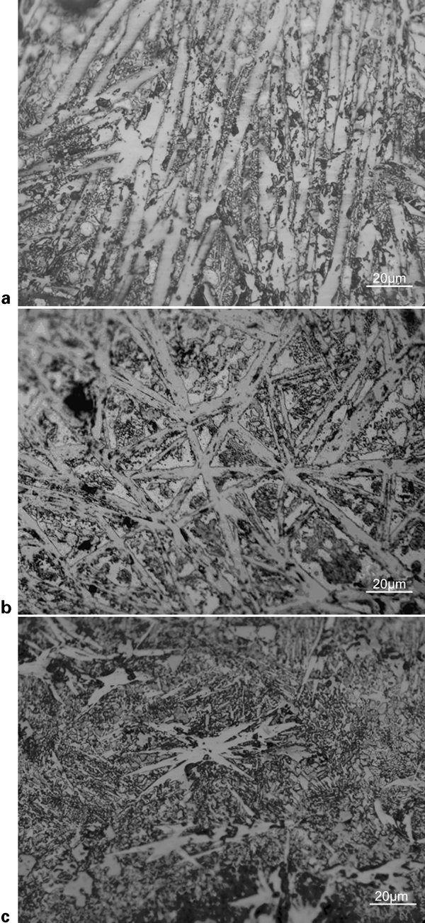
Figure 3 shows the micrographs of the cladding layer. Figure 3a shows the schematic diagram of the whole layer. Figure 3b shows the OM image of the cladding layer. It can be seen that the cladding layer consists of three parts: surface, middle and bottom. Lengths of the three parts were measured about 200–400, 0–700 and 300–400 μm for the surface, middle and bottom.
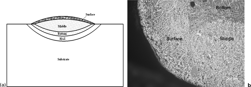
Microscope images of ZrB2/Fe cladding layer: a schematic diagram; b OM image
Figure 4 shows the cross-section view of middle part of the cladding layers obtained using 73 wt-%Zr and 27 wt-%B4C powder mixture under different cladding currents by OM. Micrographs in Fig. 4 show that ZrB2 phases became smaller and spherulitised, and distributed more uniformly with the increasing cladding current. Heat input and energy density are increased with the cladding current during the PTA cladding process. Increasing energy density can improve homogeneity of reinforcements in cladding layer.11 As the cladding current increases, the stirring action of plasma arc and convection of liquid metal are enhanced, some B4C particles floating on the surface will be immerged and spread into the liquid metals in the second stage of the metallurgical process. This is benefit for the uniform distribution of ZrB2 phases.
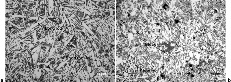
Cross-section view of microstructure of cladding layers under different cladding currents: a 140 A; b 180 A
According to the length L and the ratio of length and width (L/W) of ZrB2 particle, it can be seen from Fig. 4 that ZrB2 phases mainly have three morphologies in the cladding layer: acicular, short rod, and block. Acicular ZrB2 phases (L/W>10, L>50 μm) are mainly distributed in the surface part of the cladding layer, and some are distributed in the bottom. Short rod ZrB2 phases (2≤L/W≤10, L≤50 μm) and block ZrB2 phases (L/W<2) are mainly distributed in the middle and bottom of the cladding layer. During the cladding process reactants concentration in the surface is higher than that in other regions of the welding pool due to the floating upward of B4C powders. Therefore, in the surface part high concentration of B4C is beneficial to the nucleation of ZrB2. ZrB2 phases can also nucleation on some partially molten B4C particles in the surface part.12 Therefore, ZrB2 phases are easy to grow nuclei in the surface part. In the solidification stage of the metallurgical process, the surface part has the highest temperature gradient because of the cooling effect of shielding gas. Therefore, the surface part of the cladding layer solidifies first, ZrB2 phases nucleate early and then grow up fast to acicular shape. The bottom part solidifies earlier than the middle part for the cooling effect of the substrate. Most of ZrB2 phases in the bottom part cannot grow up due to the low concentration of reactants. ZrB2 phases in the bottom part are apt to have block shape. However, some ZrB2 nucleus can still grow along the temperature gradient direction to have acicular shape because of the inhomogeneous reactants composition distribution especially the reunion of B4C. The middle part has the lowest temperature gradient. Growth speed of ZrB2 in the middle part are rather low than that in the surface part of the cladding layer. ZrB2 particles cannot fully grow up and their sizes will be limited due to short existing time of the welding pool and the increased solidification rate. The later ZrB2 phase nucleated, the smaller ZrB2 phase will be. Therefore, ZrB2 phases in the middle part of the cladding layer have short rod or blocky morphology.
The micrographs of the cladding layer's cross-section along the depth (from the surface to the substrate) are shown in Fig. 5. With the increase in the layer depth, a significant change occurred on the appearance of ZrB2 phases. With the increase in the layer depth, sizes of ZrB2 phases gradually decreased, and ZrB2 morphology changed from acicular to blocky. In the middle of the cladding layer, it is combined by these two kinds of ZrB2 grains. The dilution rate of iron substrate is gradually increased from the top to the bottom of the cladding layer. Therefore, the concentration of the reactants is decreased from the top to the bottom of the cladding layer. More ZrB2 are produced in the surface part of the cladding layer. Because the mass density of ZrB2 is lower than that of the liquid iron based metals, ZrB2 phase will gradually float up during the reaction process. This phenomenon directly results to the vertical gradient distribution of ZrB2 content.
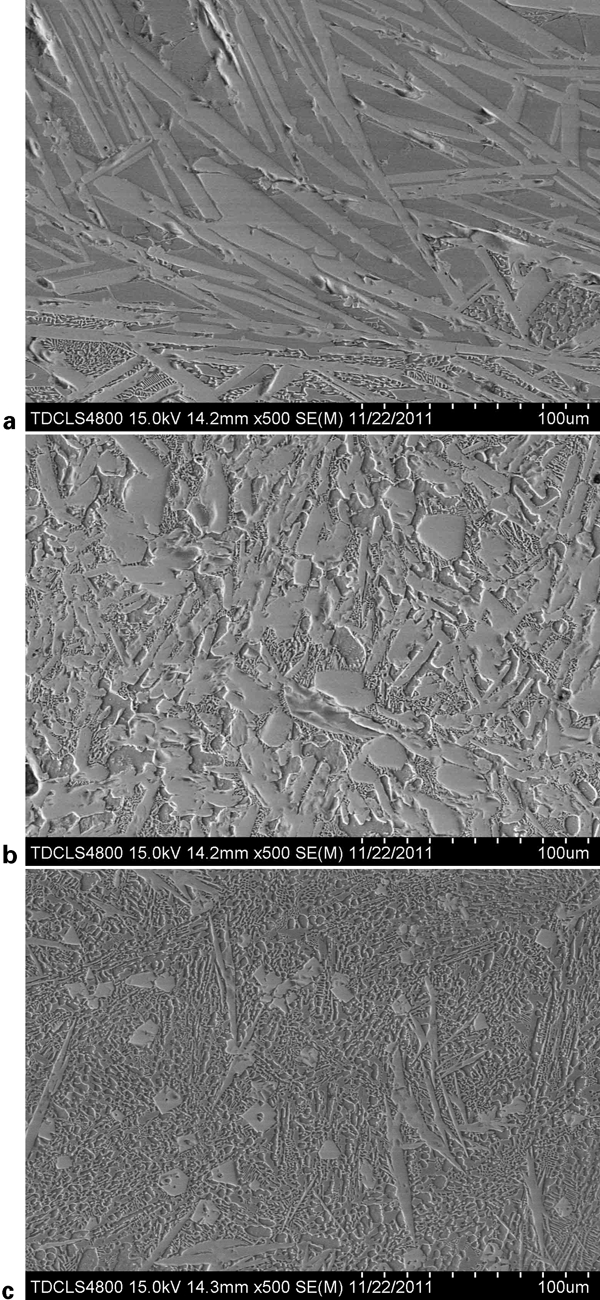
Images (SEM) of cladding layer's cross-section along vertical direction: a surface; b middle; c bottom
With the help of metallography compute analysis system, the average reinforcement dispersions of 44·90, 68·22 and 23·51% by area fraction for Fig. 5a, b and c are achieved respectively. By comparing the area fraction of ZrB2 phase in Fig. 5, it can be seen that the middle of the cladding layer had maximum ZrB2. In the bottom of the cladding layer near the fusion line, ZrB2 content was extremely low, and the size was very small (Fig. 5c). Because of the stirring effect of plasma arc, the newly formed ZrB2 will sink with hot metal liquids. While plasma heat source moved away, high temperature gradient was established in the surface part of the welding pool, but the middle of the welding pool lost heat slowly. A large number of ZrB2 concentrated in the middle of the cladding layer. Therefore, the maximum content of ZrB2 phases is in the middle of the layer.
As can be seen from Fig. 5b and c, short rod and block ZrB2 particles form particulate reinforced structure in the middle and bottom part of the cladding layer. Figure 6 shows microstructure formed by acicular ZrB2 phases in the cladding layer. Some acicular ZrB2 phases especially phases in the outmost layer of the cladding layer growing along temperature gradient direction will form the cluster structure (Fig. 6a). Other acicular ZrB2 phases overlap together forming the skeleton-like structure (Fig. 6b). The skeleton-like structure can be formed by two methods. Most of ZrB2 grains grow along different direction in the non-equilibrium solidification process. When these ZrB2 grains grow up, they will overlap together forming the skeleton-like structure. Another method is the radioactive growth of a few petal-like ZrB2 phases that are shown in Fig. 6c. These petal-like ZrB2 phases gradually grow up and ultimately overlap together forming the skeleton structure in the cladding layer.
Acicular ZrB2 phases in ZrB2/Fe cladding layer: a cluster structure; b skeleton structure; c petal-like phases
Effect of ZrB2 reinforcement on microhardness of cladding layer
Microhardness of the ZrB2/Fe cladding layer's cross-section along the depth is shown in Fig. 7. It can be seen that the microhardness along vertical direction changed obviously and appeared graded distribution. The top surface of the cladding layer has the maximum hardness: 2872 HV0·5. Microhardness changed from 2872 HV0·5 to 232 HV0·5 with the distance leaving the surface of ZrB2/Fe cladding layer, and microhardness of the matrix was only 136 HV0·5. The skeleton-like structure in the surface part of the cladding layer can greatly improve the microhardness by acicular particles affecting each other. In the middle and bottom of the layer blocky particles cannot affect each other like acicular ones. Therefore, with ZrB2 content decrease along the vertical direction and the microstructure changed from skeleton-like structure which formed by acicular ZrB2 particles to particulate reinforced structure which formed by short rod and block ZrB2 particles, microhardness along vertical direction is gradually decreased.
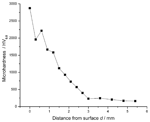
Microhardness of ZrB2/Fe cladding layer's cross-section along vertical direction
Conclusion
ZrB2 reinforcements could be in situ synthesised by PTA powder cladding with a precursor of Zr and B4C on mild steel matrix. ZrB2 phases mainly have three morphologies in the cladding layer: acicular, short rod, and block. Acicular ZrB2 mainly concentrated in the surface part of the cladding layer, short rod and block phases mainly in the middle part and the bottom of the cladding layer. In the surface part of the cladding layer acicular ZrB2 phases formed cluster and skeleton-like structure, and in the middle and bottom part short rod and block ZrB2 particles formed particulate reinforced structure. The reaction process of Zr and B4C could be divided into four stages according to the state of reactants. Resulting from the variation of mass density, dilution rate and cooling condition in the reaction process, ZrB2 particles gradient dispersed in the profile of the cladding layer along the vertical direction. Owing to presence of ZrB2 particles, the microhardness of the cladding layer was greatly improved.