
Abstract
The microstructure and hardness property of WC powder–Inconel 625 wire single tracks deposited by laser cladding at varying processing parameters were investigated using a combination of scanning electron microscopy, energy dispersive X-ray analysis, X-ray diffraction, image processing software and hardness testing. The results include the generation of process maps that predict the cladding process characteristics at varying processing conditions. High dissolution of WC particles at high energy input resulted in a decrease in retained WC volume fraction with increasing laser power. The negative dependence of the retained WC volume fraction on the transverse speed and wire feedrate showed that the decreasing powder catchment efficiency with increasing the two parameters is primarily significant to the amount of WC contained in a track. The dissolution of WC in the matrix resulted in the formation of W2C and Fe3W3C hard phases, which mainly contributed to high hardness (540–690 HV0·3) of the composite matrix.
Introduction
Laser cladding of WC–Ni based superalloy metal matrix composite coatings is becoming a prominent hardfacing technique for improving the wear and corrosion performance of engineering components.1 The established methods of producing these coatings involve lateral2, 3 and co-axial4, 5 feeding of preblended powders, combined co-axial powder and lateral wire feeding systems6 and concurrent lateral wire and lateral powder feeding systems.7 Previous studies established that concurrent wire and powder feeding systems improve the material deposition efficiency, produce composite cladding with a better surface finish and allow for an independent control of the feeding rate of the additive materials.8 The independent control of the additive material deposition rates allows for dynamic variation of the composition of the coatings during the cladding operation, thus matching their properties to the surface requirements at each position.
The abrasive performance of the WC–Ni based composite coatings shows dependence on the volume fraction and even distribution of retained WC in the coatings.9 – 11 Efforts directed towards increasing the WC volume fraction of the composite coatings include composite cladding of preblended powders of different WC powder morphologies12 and compositions.13, 14 These studies show that spherical shaped WC produced coating of a lower WC content, because they dissolve more rapidly than the ball milled (crushed) type, while a higher volume fraction was found for coating made with powders of a higher WC concentration. Laser induction rapid cladding of WC–Ni alloy coating performed at varying laser specific heat energy by Zhou et al.15 shows that minimal WC dissolution occurred in track, usually called clad, deposited with lower specific heat energy. In addition, the WC reinforced plasma transfer arc welding composite cladding with three NiCr alloys of varying Cr contents has been investigated.16 It was found that WC dissolution increases with increasing Cr content of the matrix alloys. The result was attributed to the strong Cr–C affinity, which enhances the formation of (W, Cr) C phases throughout the matrix. Usually, the volume fraction of the retained WC particles in solidified clad deposits is traced to the degree of WC dissolution that occurs during the cladding process. To date, a study of the variation of the retained WC content of WC–Ni based superalloy coatings with the main processing parameters using concurrent wire and powder lateral feeding system has not yet been reported.
This work investigates the concurrent laser cladding of WC powder and Inconel 625 wire single tracks with the aim of defining the cladding process characteristics and studying the tracks’ microstructures and hardness performance at varying processing parameters. Inconel 625 wire matrix was selected, because it exhibits a combination of high temperature strength and high resistance to corrosion and oxidation in marine environments.17 It has a density of 8·44 g cm−3. The high ductility of the alloy, due to its face centred cubic crystal structure, improves its resistance to cracking that may occur due to contraction after welding.18 As a result, the alloy has played a large role in the ability of the gas turbine engine to operate at high fractions of their melting temperatures and sustain large mechanical loads at extreme temperatures (up to 1093°C).19 WC is known to be very hard (1780 kgf mm−2) and possesses a high melting point (2720°C). Compared to the other carbides such as SiC, WC also combines favourable properties such as high density (15 630 kg m−3), low thermal expansion coefficient and good wettability with molten Ni alloys.20
Experimental
Materials and laser process
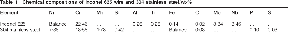
Fig. 1 shows a schematic diagram of the concurrent wire and powder laser deposition system used in this study. Deposition or cladding was performed using a 2 kW ytterbium doped fibre laser (IPG Photonics) operating at 1070 nm wavelength. The beam was focused to a small round spot of ∼3·1 at 20 mm away from focus, giving a 212 mm working distance with a Gaussian energy distribution. Inconel 625 wire of 1·2 mm diameter supplied by VBC Group (Loughborough, UK) was ‘front fed’ (ahead of the laser) at an angle of 42±1° to the horizontal so as to aim the wire tip at the centre of the meltpool. A WF200DC wire feeder (Redman Controls and Electronic Ltd) was used. Spherical WC powder (40–160 μm; mean size = 124 μm) commercially named spherotene was back-fed into the meltpool through a Praxair (model 1264) powder feeder. The powder nozzle was oriented at 67° to the horizontal so as to improve the WC deposition rate. A scanning electron microscope (SEM) image of the morphology of the WC powder is shown in Fig. 2a. Table 1 gives the chemical compositions of the wire and substrate used in this work, as quoted by the manufacturers. Plates of dimension 100×180×6 mm were machined out of austenitic stainless steel AISI 304 and used as substrate material. These were grit blasted and cleaned with acetone before the deposition runs so as to improve substrate surface laser absorptivity and remove contaminants respectively.
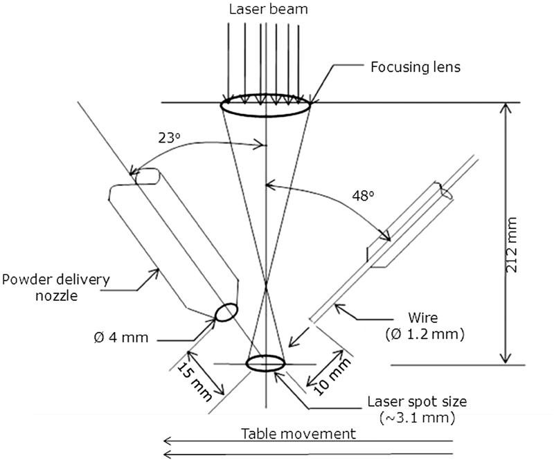
Schematic diagram of laser deposition system
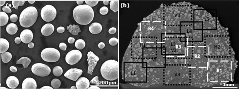
Scanning electron micrographs of a WC powder and b cross-sectioned WC–Inconel 625 wire composite track
Chemical compositions of Inconel 625 wire and 304 stainless steel/wt-%
Single track ceramic–metal composite claddings were performed at varying laser processing parameters on several AISI 304 stainless steel plates inside a transparent enclosure (bag), which was evacuated and back-filled with high purity argon gas supplied at 25 L min−1. Inconel 625 wire laser cladding process characteristics had been previously undertaken by the authors. Wire dripping (continuous dropping of molten feed wire on the substrate), wire stubbing (solid wire hitting the substrate) and smooth wire transfer occurred at different processing conditions. In this present work, Inconel 625 wire–WC powder single tracks were deposited at the processing conditions that produced wire dripping and smooth wire transfer in the previous experiment. This was carried out with the aim of understanding the effect of simultaneous injection of WC powder on the laser cladding characteristics of Inconel 625 wire. Table 2 gives the details of the parameters utilised for the cladding process.
Processing parameters
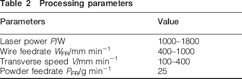
In order to understand the influence of the laser power, transverse speed and wire feedrate on the WC dissolution, hence, the fraction of the retained WC particles in the track, the powder feedrate was kept constant, while each of every other parameter was varied one at a time. A total of 48 tracks were deposited. The observed process characteristics were recorded for each of the deposited tracks.
Microstructural characterisation
Track samples, which were cut from the mid-length of all deposited composite tracks, underwent standard procedures of specimen preparation to a 1 μm finish. After, a total of 14 SEM images, each at ×200 magnification, taken at different parts of a track sample were analysed using image processing software, as shown in Fig. 2b. The volume fraction of WC contained in each micrograph was determined. The average of the values obtained from the 14 images was taken as the volume fraction of the WC retained in the track sample. Similarly, the average size of WC particles retained in the track sample was found by dividing the sum of the size (diameters) of the retained WC particles in the sample by the total number of WC particles retained in the track sample. The process was repeated for all the track samples. The elemental composition of the phases present in the microstructure was analysed using SEM equipped with energy dispersive spectrometry (EDS), while an X-ray diffractometer (XRD) was utilised for phase identification.
Hardness testing
Microhardness testing was conducted on polished cross-sectional areas of some selected track samples deposited at different processing parameters using a Buehler Micromet 2100 series microhardness tester with a load of 300 gf (i.e. 3 N) applied for 15 s. The test was performed randomly at 20 different points on the matrix and on five WC particles in the tracks so as to determine the average hardness of the matrix and the retained WC after solidification. The microhardness of the Inconel 625 wire track samples previously deposited by the authors was measured along the centreline of the tracks’ cross-sectional areas using the same method.
Definition of terms
Energy per unit length of track EL (J mm−1) is defined by equation (1). Equation (2) defines the wire deposition volume per unit length of track Vw (mm3 mm−1). The symbol d in equation (2) represents the diameter of the Inconel 625 wire.


Results and discussion
Process maps
Figure 3a is a process map developed for laser cladding of Inconel 625 wire. The process map shown in Fig. 3b is valid for the fibre laser cladding of single track WC powder–Inconel 625 wire composite coating for the range of parameters used in this experiment (see Table 2). Except for the constant powder feedrate of 25 g min−1, the process map parameters correspond to those represented by the data points in the regions 1, 2 and 3 of the process map for Inconel 625 wire only. The two maps clearly define three characteristic regions, namely, wire dripping (region 1), smooth wire transfer (region 3) and wire stubbing (region 5).
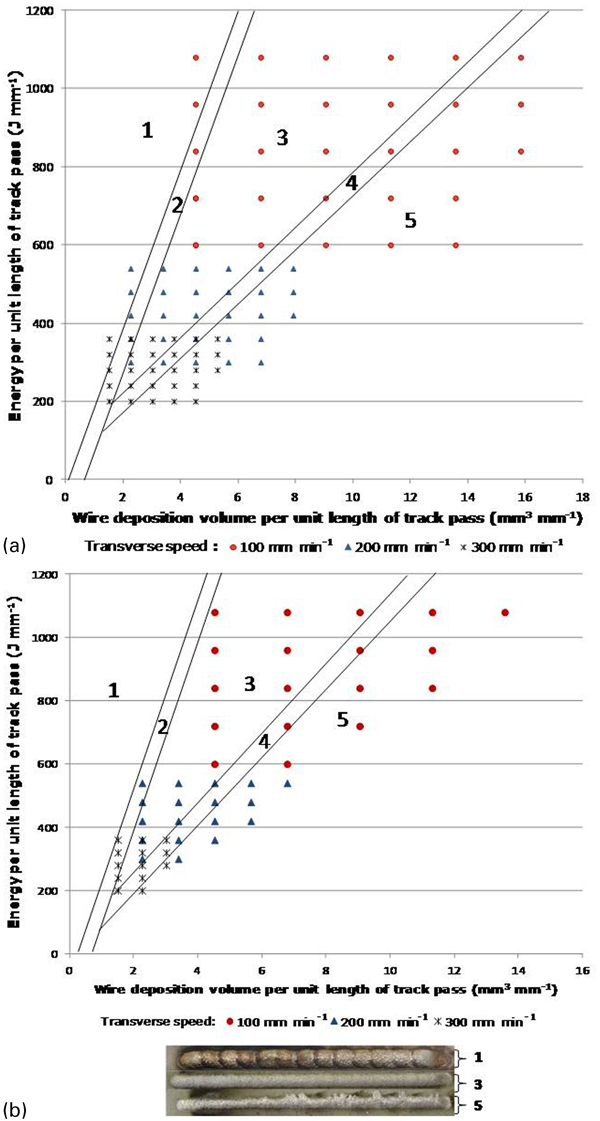
Process maps predicting fibre laser deposition characteristics of a Inconel 625 wire and b WC powder–Inconel 625 wire tracks at constant PFR of 25 g min−1 (1: wire dripping; 2: wire dripping may occur; 3: smooth wire deposition; 4: wire stubbing may occur; 5: wire stubbing regions)
A study of the two process maps shows that the top left corner (region 1) is characterised with wire dripping effect, while the bottom right corner is characterised with wire stubbing effect (see Fig. 3). Therefore, laser cladding at any process condition at these corners will result in a track of poor surface quality. Wire dripping is found to be caused by feeding too little material volume for a given energy per unit length of track pass (J mm−1); however, the map shows that the effect can be avoided by either reducing the heat energy (J mm−1) or increasing the material volume per unit length of track pass (mm3 mm−1). On the other hand, the wire stubbing effect caused by feeding excessive material volume for a given heat energy per unit length of track pass can be eliminated by either increasing the energy per unit length or decreasing the material volume per unit length of the track pass.
Additionally, the two process maps predict that smooth wire transfer may not be possible when cladding below energy input of 200 J mm−1. When compared with the process map developed for Inconel 625 wire only, a rightwards shift is noticeable in the map developed for WC powder–Inconel 625 wire laser cladding. The shift in the process map is considered to be caused by coincident WC powder injection, leading to increase in material deposition volume per unit length of track, whereas energy per unit length of track remained constant. With combined wire and powder lateral feeding system, the injected powder absorbed some fraction of the incident laser energy, thus reducing the energy absorbed by the wire tip before reaching the meltpool.
Therefore, for smooth wire transfer to occur, wire feedrate WFR must be lowered since wire tip will now require more time to interact with the laser heat energy before it can melt. Accordingly, wire dripping and wire stubbing effects, which are due to too low WFR and excessive WFR respectively for given heat energy per unit length, will now occur at lower WFR, thus shifting the process map to the right.
WC volume fraction and microconstituents
Images (SEM) of the cross-sectional area of a track at different magnifications are shown in Fig. 4. The WC particles appear larger and are of high number density in the cross-sectioned track, as shown in Fig. 4a. In Fig. 4b and c, as confirmed by EDAX and XRD results shown in Table 3, the undissolved WC marked ‘A’ appears bright contrast and near circular in appearance. The Inconel 625 matrix marked ‘B’ is dark, and the light phase with a dendritic morphology spotted as C is M6C (Fe3W3C), which has precipitated during solidification of the track from a Ni rich molten phase, which contained significant quantities of dissolved W and C. The predominant light phase marked ‘D’ around the edge of the undissolved WC is W2C produced as a result of the dissolution of WC particle in the Ni matrix.
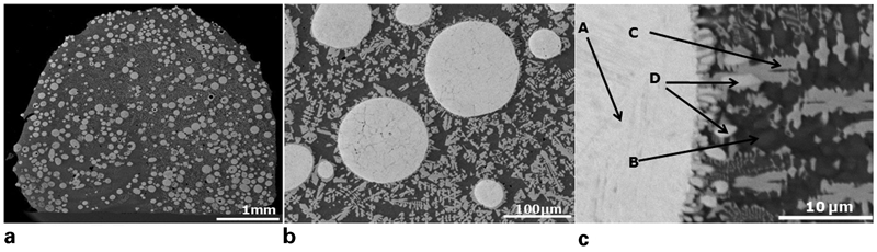
Images (SEM) showing typical microstructure of cross-sectioned sample at varying magnifications: P = 1·2 kW, V = 100 mm min−1, WFR = 600 mm min−1, PFR = 25 g min−1
Chemical analysis of phases in coating/wt-%
In order to have an understanding of the maximum WC volume fraction possible, analysis of the WC volume fraction at 100% powder catchment efficiency was conducted. The result revealed that maximum WC volume fraction theoretically lies between 58 and 78% with minimum and maximum values found at high (1000 mm min−1) and low (400 mm min−1) wire feedrates respectively.
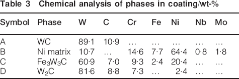
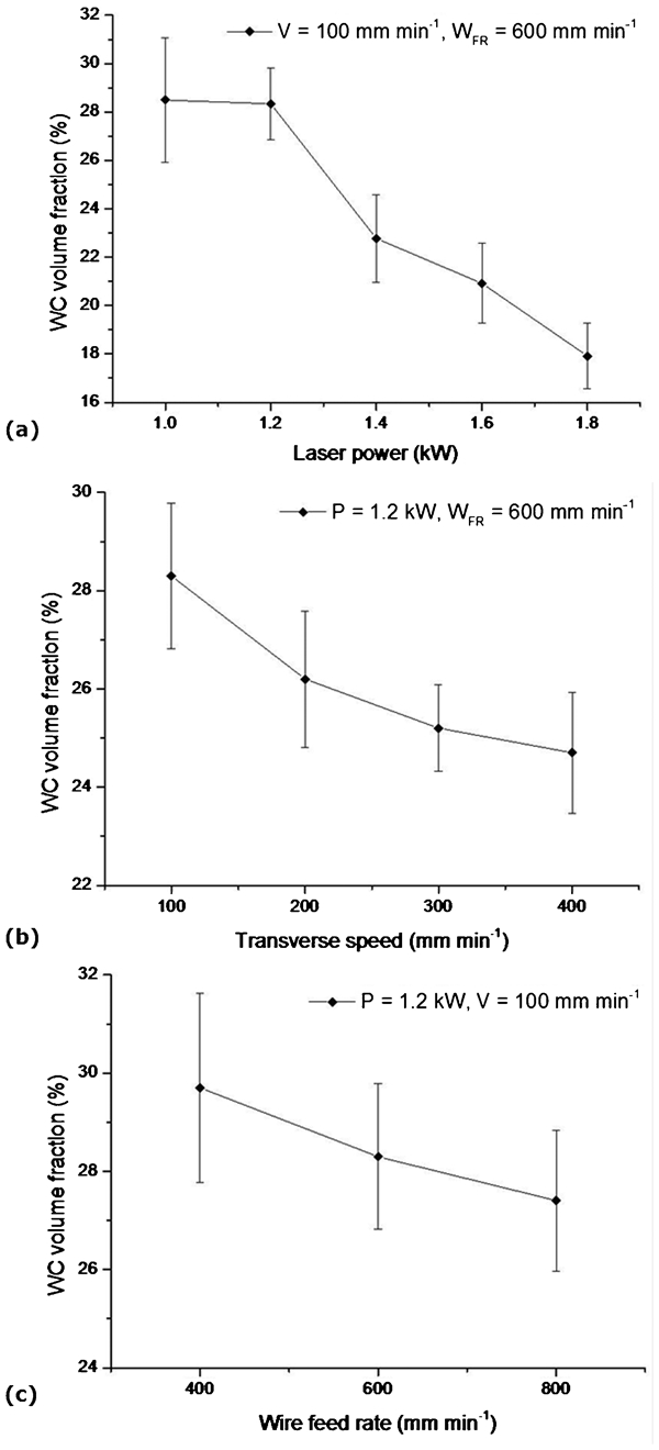
From Fig. 5, it is graphically shown that the retained WC volume fraction in the deposited tracks decreases with increasing laser power, transverse speed and wire feedrate. The increase in the retained WC volume fraction in a deposited track with decreasing laser power can be traced to the low dissolution of WC particles caused by decreasing heat energy per unit length of track. For example, 1080 J mm−1 energy available at 1·8 kW power and 100 mm min−1 transverse speed produced a high energy (very hot) meltpool. Consequently, the WC particles suffered intense heating, causing the smaller particles to dissolve completely, while the larger particles dissolved to smaller sizes, as shown in Fig. 6a. At 1·2 kW, but with the same transverse speed and wire feedrate, heat energy per unit length of track pass has significantly reduced to 720 J mm−1, producing a lower meltpool temperature; hence, there was little dissolution of WC particles as shown in Fig. 6b. In order to confirm this observation, the size of the retained WC particles in the two track samples was measured via image processing software, and the average WC particle size in the track deposited at 1·8 kW was found to be 101±12 μm, while 110±6 μm was found for samples deposited at 1·2 kW.
Effects of cladding parameters on WC volume fraction
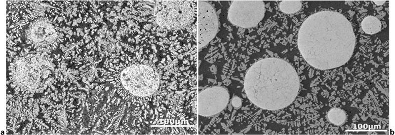
Images (SEM) of track cross-sections showing WC dissolution at laser power of a 1·8 kW and b 1·2 kW: V = 100 mm min−1, WFR = 600 mm min−1, PFR = 25 g min−1
Previously, an increase in the retained WC volume fraction with an increasing transverse speed during laser cladding of preblended WC–Ni alloy powder was attributed to low WC dissolution as the speed increases.21 However, the current result proves that the reverse is the case with concurrent wire and powder laser cladding. A possible explanation is that powder catchment efficiency plays a role. Since energy per unit length of track pass decreases with increasing transverse speed, a smaller meltpool size is therefore produced at a higher transverse speed. In addition, it would be expected that all feed wire entered the meltpool but, practically, not all powder was trapped in the laser meltpool, since catchment efficiency is less than unity.
Consequently, powder catchment efficiency reduces, whereas the wire deposition rate remains nearly the same as the transverse speed increases. WC dissolution is found to decrease with increasing transverse speed; however, the overall decrease in retained WC volume fraction with increasing speed shows that the reducing effect of powder catchment efficiency with increasing transverse speed is more significant than WC dissolution.
The decrease in the retained WC volume fraction with increasing WFR is due to lower assimilation (catchment efficiency) of the WC particles at higher WFR. Increasing the WFR means more wire volume is delivered to the meltpool per unit time. Since the laser power and transverse speed is constant, the thermal energy per unit length of the meltpool is also constant. Therefore, at higher WFR, the energy content of the meltpool is rapidly transferred during solidification, thus reducing the fluidity and activeness of the meltpool in a short time. Hence, track solidification is expedited. As a result, only a small volume of powder particles could make it into the meltpool before the meltpool solidifies, while others were bounced away to the surrounding cladding area.
Hardness testing
Vickers microhardness measurements of the track samples were made randomly on their cross-sectional areas, and the results are presented in Table 4. Compared with the hardness value of the stainless steel plate (201 HV0·3) and laser deposited Inconel 625 tracks (220–280 HV0·3) made without WC powder injection, the hardness of the matrix of the composite track ranged from 540 to 690 HV0·3, while the average WC particle hardness in the composite track ranged between 2100 and 2400 HV0·3. The result shows that the improved hardness demonstrated by the matrix of the composite tracks is due to injection of WC particles whose dissolution resulted in the formation of hard W2C and Fe3W3C phases.16
Summary of hardness property of WC powder–Inconel 625 wire composite tracks
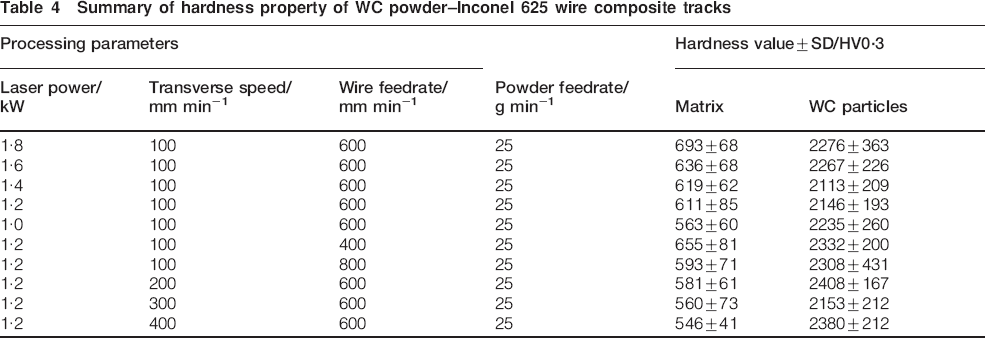
The results presented in Table 4 show that the composite track microhardness varied directly with the laser power but inversely with the transverse speed. These relationships were traced to the degree of WC dissolution with the processing parameter. At a high transverse speed or low laser power, there was low energy input and the particle dissolution was low. As a result, the formation of the hard phases (i.e. W2C and Fe3W3C) was low. However, at high power or a low speed, the particle dissolution was high and more hard phases were present, giving rise to hardness of the track. The inverse relationship between the hardness and wire feedrate is believed to be caused by the increased percentage volume composition of the relatively soft Ni matrix at a higher wire feedrate in the track microstructure.
Conclusion
A process map predicting the process characteristics of the concurrent laser cladding of WC powder–Inconel 625 wire single tracks at varying processing parameters has been developed. Compared with the process map developed for Inconel 625 wire only, the rightward shift in the map is a direct product of WC powder injection into the cladding process. The effects of processing parameters on the volume fraction of the retained WC particles in the deposited composite tracks have been studied. The retained WC volume fraction was found to decrease with increasing laser power as high WC particle dissolution occurred at high energy per unit length of track. Although low WC particle dissolution was expected at a high transverse speed, the negative dependence of the retained WC volume fraction with increasing transverse speed revealed that powder catchment efficiency, which varies inversely with the speed, mainly affects the volume fraction of the WC retained in the composite tracks. The retained WC volume fraction decreased with the wire feedrate. The decrease was attributed to low WC powder assimilation in the meltpool at a high wire feedrate. For the range of parameters used in this experiment, a maximum of 30% volume fraction of undissolved WC was found to be possible for the concurrent WC powder–Inconel 625 wire composite laser cladding. Because of the formation of hard phases including W2C and Fe3W3C in the track microstructure, WC powder–Inconel 625 wire composite tracks (540–690 HV0·3) are >200% harder than Inconel 625 wire tracks (220–280 HV0·3) deposited at the same parameters.
Footnotes
Acknowledgements
T. E. Abioye appreciates the Petroleum Technology Development Fund, Nigeria, for sponsoring his PhD program.