
Abstract
To improve the wear resistance of copper through in situ synthesis of ceramic particulate reinforcement, laser surface modification on copper was performed using a powder mixture of Ni based alloy with (Ta2O5+C) doping. The microstructure, microhardness, wear resistance and bulk electrical conductivity of the integral material were investigated. The results indicated that the modified layer had a homogeneous fine microstructure containing TaC particles and Cr3C2 acicular phases dispersed uniformly in the matrix of γ (Ni,Fe) and (Cu,Ni,Fe) solid solutions. The modified layer exhibited higher hardness and better wear resistance than the Ni based alloy modified layer because of the presence and the uniform distribution of in situ synthesised TaC particles. However, the addition of TaC particles slightly decreased the electrical conductivity of the integral bulk.
Introduction
Copper and its alloys are extensively used in the industry because of their high electrical conductivity. They are also ideal candidates for the rail of electromagnetic railguns.1, 2 However, their low strength and poor wear resistance affect their service lives. Cu alloys fabricated using traditional methods exhibit improved mechanical properties with deteriorated electrical conductivity. Thus, the laser surface technique, an advanced manufacturing method, has been introduced to overcome this problem. Several studies have reported on laser cladding of Cu with Ni based alloy,3 – 8 which occurs because of the complete miscibility between Cu and Ni and the good wearability of Ni based alloy coating. Results have shown that laser cladding highly improves the wear resistance of Cu. However, the effects of laser cladding on electrical conductivity have not been discussed thus far. In our previous study,9 a different process to retain electrical conductivity was demonstrated. Our findings indicated that the wear resistance of Cu was enhanced without impairing much of the bulk properties, which proved laser surface modification is an effective method under appropriate conditions.
For railguns, higher wear resistance with retained conductance than that in the previous results must be produced. In situ synthesised ceramic particulate reinforced metal matrix composites have high strength and toughness, which can enhance the characteristics of the metal surface.10 In the recent years, several researchers fabricated reinforcements to enhance wear resistance via in situ laser synthesis. For instance, Das et al.11 deposited TiB–TiN reinforced Ti6Al4V alloy composite coatings on pure Ti substrate via in situ laser processing. Li et al.12 synthesised TiN–TiB composite structure on Ti–3Al–2V alloy in situ via laser cladding. Zhao et al.13 laser cladded Fe–Al–Si composite coating on steel in situ. Therefore, discussing the in situ synthesis of ceramic particles via laser surface modification to strengthen the Cu surface is necessary.
TaC has remarkable properties, such as high hardness (Mohs hardness of 9–10), high melting point (≥3880°C), high chemical stability, good resistance to chemical attack and thermal shock, and excellent oxidation resistance and corrosion resistance.14 These attributes make TaC a good choice for a number of applications. For instance, TaC is added into sintered WC–Co cemented carbide alloys to enhance their hardness, thermal shock resistance, and oxidation resistance.15 Studies on the in situ synthesis of TaC on steel have also been performed.14, 16, 17 TaC particles are synthesised through in situ reaction in laser cladding coatings, in which the hardness and wear resistance of the coatings have been improved because of the presence of in situ synthesised TaC particles.
However, in situ synthesis of TaC particles in Ni based alloy modified layer for Cu enhancement and the effect of adding TaC on the electrical conductivity of Cu have not yet been reported. In the present study, laser surface modification of Cu was performed using a powder mixture of NiCrBSi alloy with (Ta2O5+C) doping.
Experimental
As received Cu (99·9 wt-%Cu; 50×25×5 mm), sandblasted and rinsed with acetone, was used as the substrate in this study. The powder was mixed with NiCrBSi alloy powder (grain sizes of 45–100 μm), tantalum pentoxide (Ta2O5, 99·5% purity and ≤20 μm size), and graphite (C, 99·8% purity and ≤30 μm size). The composition of the NiCrBSi alloy is as follows: 0·8–1·0 wt-%C, 3·5–5·5 wt-%Si, 3–4·5 wt-%B, 8–10 wt-%Fe, 16 wt-%Cr and Ni, balance. The powder mixture designed with 20 wt-%(Ta2O5+C) was prepared using a QM-ISP04 ball mill for 1 h, in which the mole ratio of Ta2O5/C was 1∶7.
The powder mixture with a thickness of 0·9 mm was preplaced on the substrate with cellulose acetate acetone and dried in a furnace at 100°C for 1 h. Subsequently, the preplaced specimens were irradiated using a continuous wave CO2 laser with single or multiple tracks for the tests. After conducting a series of prior trials, the optimum processing parameters used in the experiments were as follows: laser power, 2 kW; beam diameter, 5·0 mm; scanning speed, 4 mm s−1 and overlapping ratio, 40%. Cu matrix enhanced by pure NiCrBSi powder was also prepared under similar conditions for comparisons.
After laser processing, the samples were sectioned and polished for measurement purposes. The microstructure evolution of the sample etched in 8 wt-% aqueous FeCl3 solution was examined under a Jeol JSM-6700F scanning electron microscope (SEM) equipped with Inca Energy energy dispersive spectrometer (EDS). Phase identity was determined using an X'Pert Pro PW3071 X-ray diffractometer (XRD) with Cu Kα radiation, operated at 40 kV and 40 mA and a scanning speed of 6° min−1. The hardness tests were performed along the depth of the cross-section using a Vicker microhardness tester (HXD-1000) with a load of 100 g for a holding time of 15 s. Wear tests were performed on MRH-3 block-on-ring wear testing machine under dry sliding conditions at room temperature. The sample was fixed on a stationary holder; the counterpart was a GCr15 steel ring with a diameter of 49·2 mm and hardness of 60·5 HRC. All tests were performed with a load of 60 N and a test time of 15 min at a speed of 290 rev min−1. The wear mass loss was calculated using an electronic balance with a sensitivity of 0·1 mg before and after each test. The electrical resistance of the integral bulk with sizes of 20×2×5 mm was determined by four-probe DC for the application on an electromagnetic railgun.9
Results and discussion
Microstructure
The XRD pattern of the modified layer is shown in Fig. 1. According to the indexed results of the diffraction peaks in terms of Powder Diffraction File, the phases of the modified layer consist of TaC, Cr3C2, γ (Ni,Fe), and (Cu,Ni,Fe) solid solution. Although the carbide peaks cannot be easily identified, the presence of Cr3C2 can be confirmed by the SEM graphs and EDS data. This phenomenon can be primarily attributed to the higher relative peak intensity of Cu than that of Cr3C2. In addition, the generation of TaC possibly influenced the peak intensities of Cr3C2.
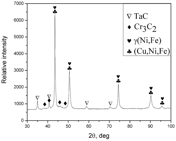
X-ray diffraction pattern of NiCrBSi+(Ta2O5+C) modified layer
The SEM photographs of a cross-section of the modified layer are shown in Fig. 2. The modified layer was crack free and exhibited a homogeneous fine microstructure that comprises particles, acicular phases, and a solid solution matrix. The microstructure on top (Fig. 2a) consists of numerous white particles and small grey phases uniformly dispersed in the matrix. In the middle (Fig. 2b), the grey phases became acicular. However, the microstructure at the bottom (Fig. 2c) was mainly composed of numerous small white particulates and grey phases uniformly distributed in the matrix, with a few large white particles. The grain boundary of Cu was observed at the interface between the modified layer and the substrate (Fig. 2c).
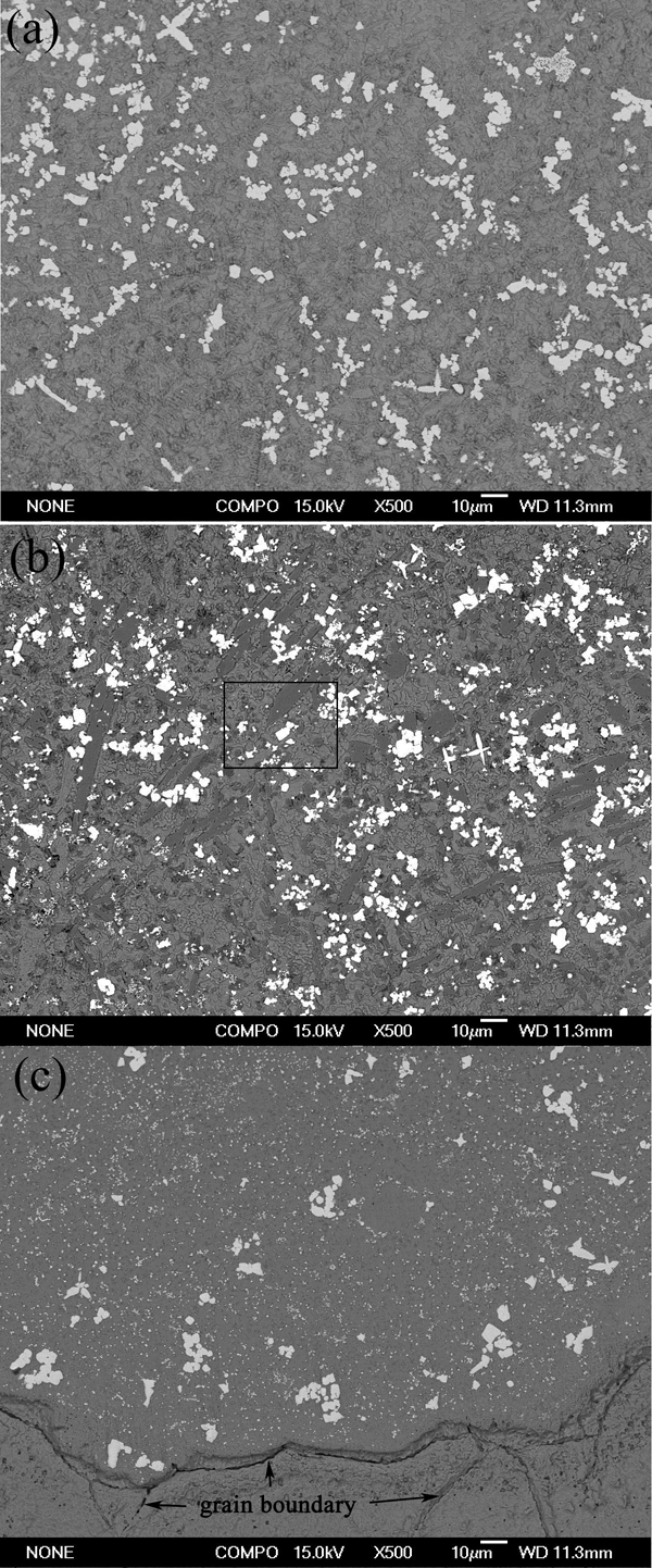
Cross-sectional microstructure of a top, b middle and c bottom of modified layer
Figure 3 shows the magnified SEM micrograph that corresponds to the area marked by a black rectangle in Fig. 2b. The typical microstructures of the white granular phase (P1) and the grey acicular phase (P2) were uniformly embedded in the matrix formed by the solid solution mixture (P3 and P4). The elemental compositions of the phases are listed in Table 1. Based on the XRD results (Fig. 1), P1 and P2 correspond to TaC and Cr3C2 respectively, which are the predominant reinforcements of the modified layer. P3 was relatively abundant in Ni and Fe, with a few Cr and Si, whereas P4 contains a certain amount of Cu. Thus, γ (Ni,Fe) and (Cu,Ni,Fe) solid solutions comprise the layer matrix.
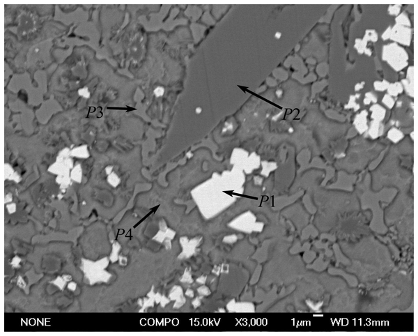
Magnified SEM micrograph of middle of layer in Fig. 2b
Composition of various phases of modified layer*/at-%
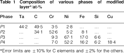
Error limits are ±10% for C elements and ±2% for the others.
Ta2O5 initially reacted with C to form TaC because of the low Gibbs free energy of the reaction.18 Cr3C2 was produced from the reaction of Cr with C because the addition of C yielded a high C content in the pool.16 TaC and Cr3C2 precipitated as the predominant phase and freely grew into particle or acicular constituent. The residue rapidly solidified into γ (Ni,Fe) and (Cu,Ni,Fe) solid solutions. Cu atoms appeared in the layer and formed solid solutions with Ni as the substrate was diluted. However, solidification is a fast and non-equilibrium process, and the alloy solution is not uniformly distributed in the mixture. Some precipitated as γ (Ni,Fe) solid solution without Cu atoms, whereas others formed a (Cu,Ni,Fe) solid solution with a certain amount of Cu.
Solidification starts at the bottom of the molten pool and lasts for a short period when the beam moves forward; thus, TaC nucleates spontaneously and precipitates massively as small particles. Cr3C2 crystallises into small acicular or particulate phases. Some TaC particles in the first crystalline phase increased in size because of intense convection (Fig. 2c). The solidification in the middle portion of the molten pool began when the solid/solution interface proceeds along the surface normal. The duration of the solidification in the middle was longer than that at the bottom because of the decrease in both temperature and temperature gradient. Therefore, the TaC particles increased in size and Cr3C2 became the coarse acicular phases. Solidification lasted slightly shorter at the top than in the middle because the airflow cooled the surface. Therefore, the grey phases do not have enough time to become acicular.
Microhardness
The hardness profiles of the NiCrBSi+(Ta2O5+C) and NiCrBSi modified samples are shown in Fig. 4. The average hardness values of the NiCrBSi+(Ta2O5+C) and NiCrBSi samples and the Cu substrate were approximately 918, 590, and 90 HV0·1 respectively. The average hardness of the NiCrBSi+(Ta2O5+C) sample was enhanced by ∼56% Compared with that of the NiCrBSi sample. According to the analysis in the section on ‘Microstructure’, a large number of TaC particles with high hardness levels were synthesised in situ and dispersed uniformly in the matrix. Thus, the hardness was significantly improved.
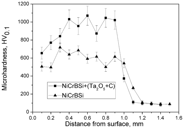
Microhardness profile along cross-section of modified layer
Wear resistance
The mass losses of the NiCrBSi and NiCrBSi+(Ta2O5+C) specimens were 2·2±0·1 and 0·9±0·1 mg respectively. The NiCrBSi+(Ta2O5+C) specimen yielded a 2/5 wear mass loss in contrast to that of the NiCrBSi specimen. Figure 5 illustrates the morphologies of the worn surfaces of these specimens. In particular, the worn surface of the NiCrBSi+(Ta2O5+C) specimen was relatively smooth and flat, with only a few slight scratches (Fig. 5a). By contrast, the worn surface of the NiCrBSi specimen was characterised by a larger number and deeper ploughing grooves than the former (Fig. 5b).
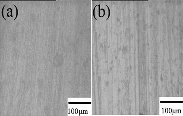
Wear patterns of a NiCrBSi+(Ta2O5+C) and b NiCrBSi modified layer
The wear resistance improvement of the NiCrBSi specimen can be attributed to the presence of numerous CrB/Cr3C2 hard phases.9 However, these coarse and brittle hard phases form fractures and debris under stress, leading to abrasive wear. In contrast to the NiCrBSi specimen, in situ synthesised were firmly bound to the matrix and exhibited greater hardness and strength in transferring stress than CrB/Cr3C2. The TaC particles do not easily form fractures during wear tests. Therefore, the wear mechanism of the NiCrBSi+(Ta2O5+C) specimen was mildly adhesive.
Electrical conductivity
The resistivity data (ρ) and the International Annealed Copper Standard conductivity values (%IACS) of the specimens are listed in Table 2, in which the electrical conductivity of both modified samples was lower than that of the Cu substrate. The conductivity of the NiCrBSi+(Ta2O5+C) specimen decreased by ≤4% compared with that of the NiCrBSi specimen. This slight decrease in electrical conductivity can be attributed to the in situ synthesised TaC. Considering the measurement errors, the doping of the TaC particles does no greatly affect the electrical conductivity. Thus, the decrease was mainly caused by the NiCrBSi alloy. Therefore, the in situ synthesised TaC particles significantly improved the wear resistance of Cu and slightly decreased the electrical conductivity.
Electrical conductivity of specimens*
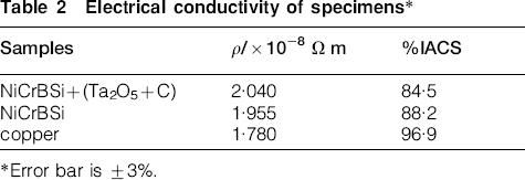
Error bar is ±3%.
Conclusion
Cu was successfully enhanced by adding TaC particles, which were in situ synthesised by laser surface modification with NiCrBSi+(Ta2O5+C) powder mixture. The in situ synthesised TaC particles were dispersed uniformly in the matrix of γ (Ni,Fe) and (Cu,Ni,Fe) solid solutions.
The average hardness of the modified sample was enhanced to 918 HV0·1, which is 1·56 times higher than that of the Ni based alloy modified sample, because of the presence and the uniform dispersion of TaC particles. Moreover, the wear resistance was improved by a factor of 2·5 compared with that of the Ni based alloy modified sample.
The decrease in bulk electrical conductivity mainly depends on the Ni based alloy. Moreover, doping of the TaC particles significantly improved the wear resistance of Cu as the electrical conductivity was slightly decreased.
Footnotes
Acknowledgements
This work is supported by the Natural Science Project of Henan Province Education Department (grant no. 2011B140022) and the Technologies R&D Program of Zhengzhou City (grant no. 112PPTGY219-9).