
Abstract
The deposition of pore free and highly adhered Ni and Co superalloy coatings is of great interest for engine design and gas turbine applications, both in case of maintenance repair and overhaul operations as well for mechanical and chemical protection purposes in aeronautics and energy applications. This study would like to give a wide overview about the capability of cold spray technology on this topic: two different commercially available deposition systems, Sulzer-CGT Kinetiks 4000 and Plasma Giken PCS-1000, were compared, and deposition processes with both nitrogen and helium as carrier gas have been explored. Microstructural investigation, microhardness and adhesion results are reported to depict a preliminary scenario of coating properties. Fully dense coatings with thickness >1 mm and adhesion >50 MPa are obtained using helium, while quite porous, 20 MPa adhered coatings are obtained using nitrogen. Finally, general considerations about the potential applicability of those coatings for repair purpose in aerospace applications are pointed out.
Introduction
Superalloys are traditionally and extensively employed for the realisation of gas turbine parts and high temperature engines in aeronautic and energy applications thanks to their excellent mechanical, thermal and corrosion resistance properties.
1
These characteristics are responsible at the same time for the high efforts necessary for manufacturing and machining these parts, leading, as a consequence, to high time and costs for production. For these reasons, maintenance repair and overhaul (MRO) operations and coating deposition technolgies able to restore damaged parts are of great interest in this field.
2
Nowadays, nickel and cobalt based coatings used in industrial applications are mainly deposited by thermal techniques: electric arc,
3
air plasma spray,
4
high velocity oxy-fuel,5,6 laser,
7
electrospark deposition
8
and joining by diffusion induced isothermal solidification of a liquated insert metal
9
are the widely diffused methods to process high strength alloy coatings. The major drawbacks of thermal spray techniques are related to the thermal input during the deposition:
10
for example, on steel substrates, the deposition of the first layers of coating could involve the damage or increase in brittlness at the substrate/coating interface where sometimes long discontinuity lines along the coating/substrate interface may occur. On the other side, the occurrence of heat affected zones on precipitation alloys such as the most part of superalloys itself could lead to the solubilisation or recrystallisation or simply grain growth generally combined with a loss of mechanical properties and strength. Furthermore, porosity and residual stresses developed in the coating during the cooling down from deposition temperature to room temperature could allow pitting and subsequently promote blistering and coating spallation in corrosive environments.
11
It is clear that in this scenario the possibility to benefit from a low temperature deposition process can be seen with great interest, and among the low temperature deposition processes, cold spray (CS) has been receiving increased attention during the last years for the deposition of metallic and ceramic–metallic coatings. Cold spray is a fully solid state powder deposition process, which allows to produce coatings with reduced oxide content, low residual stresses and high efficiency.
12
The reduced porosity and oxide content in CS layers are the key factor to suggest CS for the obtainment of high thickness coatings with improved corrosion and oxidation resistance. Looking at the deposition of high strength materials by CS, the main critical aspects are related to the high plastic deformation of impinging particles required for an optimised deposition. The extremely high yield strength, combined with the high melting temperature, is the main reason responsible for the high critical velocity for cold spraying of superalloys.
13
Furthermore, the quality of a coating (where quality means the compactness of the microstructure with lack of porosity and the mean mechanical properties, in particular cohesion and adhesion) increases progressively with the difference between impact velocity and critical velocity.
14
The increase in this difference that is the tool to maximise the coating quality can be obtained by two different ways: the increase in the impact velocity and the reduction of the critical velocity. Regarding the first way, generally it is obtained by increasing as much as possible the gas velocity, which is the reason of the effort for the production of deposition system with higher operating pressure and temperature. In this sense, it must be taken into account that both pressure and temperautere influence the gas velocity, and in particular, the increase in the inlet temperature results in larger gas velocity after expansion through the de Laval nozzle. The increase in the gas velocity can be also obtained by changing the carrier gas, and in this sense, it is well known that the use of helium is enourmosly beneficial.
15
Regarding the second way, a general relation for critical velocity that can be considered is as follows
14
This study would like to make clearer the situation about the effectiveness of using CS technology for the deposition of superalloy coatings. Waspaloy has been selected as base and coating material because of its high mechanical properties and wide employment for the manufacturing of aeronautic and industrial gas turbines; two different commercially available deposition systems, Sulzer-CGT Kinetiks 4000 and Plasma Giken PCS-1000, were compared as well as the deposition processes with both nitrogen and helium as carrier gas has been explored. Only as deposited coatings have been considered in order to focus the attention on pure CS performances.
Experimental
Powders
Commercially available gas atomised Waspaloy powders have been employed in this study supplied by LPW Technology Ltd. Certified size distribution was −45+15 μm evaluated by laser scattering (Mastersizer 2000, Malvern, UK). The powders exhibit spherical shape with the presence of some small satellites stitched to the exterior surface as shown in scanning electron micrographs reported in Fig. 1. Powder microhardness was measured by microindentation (Leica VMHT) with 15 and 25 gf resulting to 363±29 and 328±23 respectively.
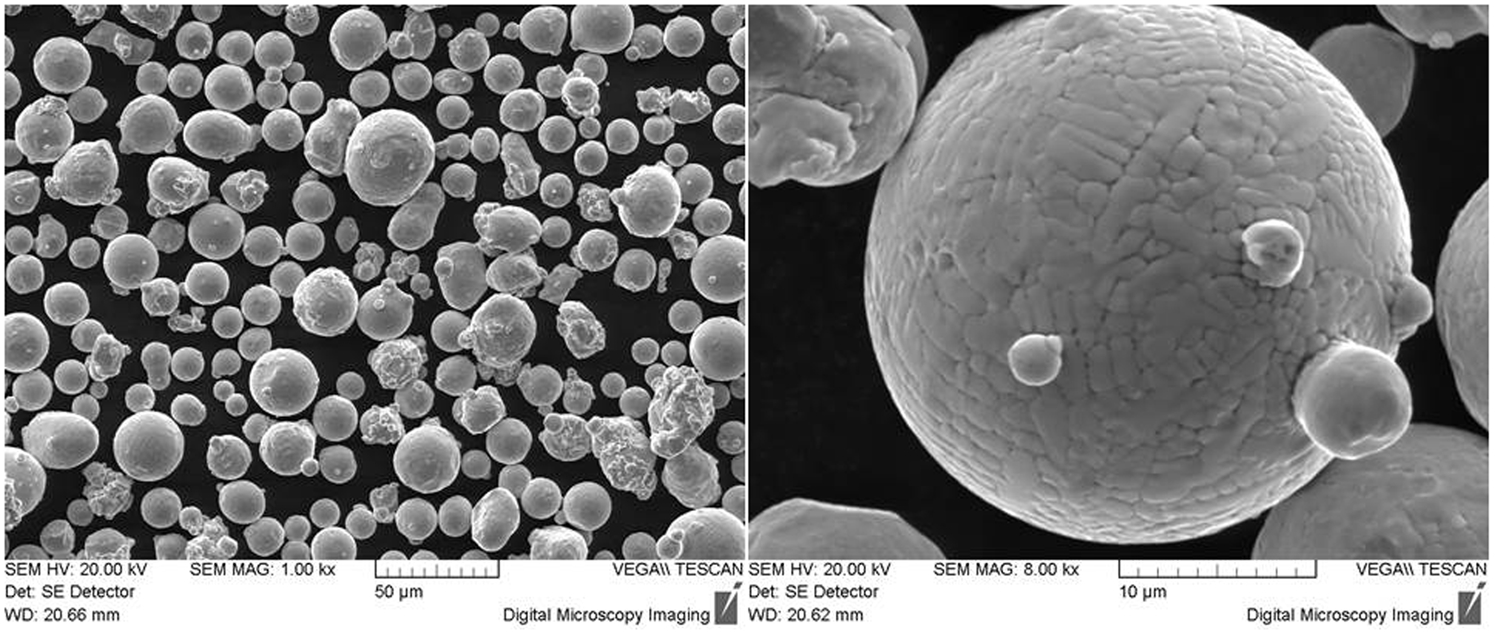
Scanning electron micrographs of Waspaloy feedstock powders
Deposition
The coatings have been deposited using different deposition system and process conditions. Firstly, Kinetiks 4000 (Sulzer Metco Management AG, Winterthur Switzerland) and PCS-1000 (Plasma Giken Co. Ltd, Tokyo Japan) deposition systems have been compared by optimising the deposition processes of a single layer 0·6 up to 1·3 mm thick coating obtained with nitrogen as carrier gas. Then, the employment of helium has been considered only with PCS-1000 system for the deposition of a full thickness 1·2 mm single layer coating and also a bilayer coating consisting of a ∼0·2 mm thick bond coat followed by a 1·0 mm top coat deposited respectively with helium and nitrogen as carrier gases. Deposition parameters close to the maximum allowed by the respective plants have been used in order to achieve the best coating performances. Kinetiks 4000 system has been equipped with air cooled silicon carbide nozzle (supplied by Impact Innovations GmbH, Ampfing, Germany) that is able to enhance the process reliability delaying noticeably the clogging occurrence. On the other hand, PCS-1000 deposition system is equipped with standard water cooled nozzle. Considering the substrates, the whole deposition plan has been performed onto Waspaloy substrates in order to simulate a general repair procedure of an aeronautic turbine part. 50×30×3 mm plates obtained from Waspaloy AMS 5544 sheet has been employed for process optimisation and microstructural investigation, while Ø25·4 mm substrates obtained from AMS 5708 bar has been employed for adhesion samples. Substrate microhardness was 444±96 Vickers (500 gf). Two different substrate preparations were considered: machined and sandblasted (16 mesh corundum) finishing. Mean roughness, Ra, <1 μm was measured in the machined surface, while ∼8 μm was reported in the sandblasted one. The layout of process conditions for the most representative processes and produced specimens is reported in Table 1.
Process conditions and set of samples investigated in this study
Coating characterisation
The deposited coatings W0–W5 have been investigated in order to depict the main microstructural and mechanical properties. The microstructure observation was carried out by means of light optical microscope (Leica DM6000M) and scanning electron microscopy (FEI FIB-SEM dual beam NOVA 600NANO LAB, Hillsboro, OR, USA). Porosity, as well particle deformation and qualitative aspect ratio, has been determined by cross-section observation. The mechanical characterisation consisted of the evaluation of the coating microhardness and coating adhesion. The Vickers microhardness (Leica VMHTAUTO microhardness tester) has been measured on as deposited mechanically polished up to 1 μm with water based diamond suspension (Presi, Diamond Suspension Reflex LDP) cross-section samples; indentation loads of 25 and 500 gf have been employed. The evaluation of coating adhesion has been performed according to the norm ASTM C633. The pull off apparatus was an MTS mechanical testing machine (MTS, 14000 Technology Drive, Eden Prairie, MN) under force control, and the load was measured by a 50 kN load cell (MTS). Averages and standard deviations of three measurements per set were calculated. Fractography investigation by scanning electron microscopy (SEM) was performed on selected samples in order to have information about the particle–particle bond. The samples were prepared first by removing the substrate obtaining a free standing coating, then performing a small cut on the back side of the coating to induce the fracture and then bending the free standing specimen up to the rupture.
Results and discussion
Microstructure
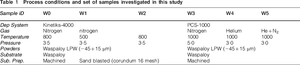
A set of Waspaloy coatings of thickness ranging from 0·7 to 1·5 mm have been sprayed onto Waspaloy substrate, and five different coatings, W1–W5, according to Table 1, have been selected and devoted to microstructural investigation. The coating W0 deposited with N2 boosted Kinetiks 4000 onto relatively smooth surface of machined substrate exhibited no adhesion, and just after the deposition, it is easily removed, leaving a brittle free standing coating. Coating adhesion is one of the key properties to validate a repair procedure, and for this reason, the process and coating W0 has been excluded from the characterisation plan. Figure 2 shows a collection of cross-section light optical micrographs of samples W1–W5. Both as deposited coatings and chemically etched (Beattie and Hagel, 5 mL H2SO4, 3 mL HNO3 and 92 mL HCl) are reported. The characterisation has been focused taking into account two main guidelines according to the coating preparation plan. First, a comparison between the performances and characteristics of coatings was obtained, employing nitrogen as carrier gas and different deposition systems, coating W1–W2 and W3 respectively with Kinetiks and PCS-1000 systems. Secondly, a comparison between performances and characteristics of coatings was obtained, employing nitrogen, helium and helium+nitrogen as carrier gas with PCS-1000 deposition systems, W3, W4 and W5 coatings respectively. The first remark concerns a noticeable difference in terms of coating porosity as reported in Fig. 3; starting from the bottom, PCS-1000 helium deposited coating, W4, exhibits porosity <0·4% (areal on cross-sectioned coating), while the coatings deposited using nitrogen as carrier gas exhibit porosity of ∼1·3 and 0·8% in case of PCS-1000 (W3) and Kinetiks (W2) deposition system respectively. It must be taken into account that the evaluation of the whole porosity is affected by the coating cohesion and preparation procedure. During the grinding, some particles weakly bonded, or rather characterised by low cohesive energy, can be pulled out from the cross-section surface, leaving an apparent pore. This does not represent real porosity but rather induced porosity and cannot be distinguished from the real one by the micrographic observation. Thus, the measured porosity is generally higher with respect to real porosity, and this is in particular observed when coating characterised by low cohesive energy is characterised. In this case, both coatings deposited with nitrogen are generally affected by this problem. For this reason, the implemented procedure was to perform automatic mechanical polishing of the whole set of investigated samples simultaneously in order to allow a correct comparison, in relative, among the whole set. The coating W5 realised by the superposition of a bond coat (He) and a top coat (N2) can be considered by the microstructural point of view as a perfect bilayer, where the whole coating consists of the sum of two separate layers with features and characteristics of W4 (pure helium) and W3 (pure nitrogen) coatings. This is highly evident from the cross-section micrograph, where a sharp interface between the two layers is observed.
Light optical micrographs of cross-sectioned W1–W5 coatings; whole view, magnification ×50 (left) and detail of substrate/coating interface after chemical etching, magnification ×200 (right)

Total porosity of W1–W4 coatings
Concerning the comparison of coatings deposited with nitrogen, a representative selection of cross-section SEM images is shown in Fig. 4. The substrate/coating interface is shown in Fig. 4a–c in case of samples W1–W3, while a detail of coating microstructure is emphasised in Fig. 4d and e in case of samples W2 and W3 respectively. The porosity is highlighted by white arrows on the micrograph; sample W1 shows noticeable porosity in particular at the interface with the substrate and very weak particle–particle deformation and bonding, and the contours of the particles are clearly visible confirming weak cohesion and diffused porosity at the particle–particle boundaries. Samples W2 and W3 show no significant difference in coating porosity, microstructure and particle deformation as reported in Fig. 3 and Fig. 4b–e. Slighter higher porosity is observed in sample W3; its shape is mainly elongated and it is distributed and condensed along the contours of the particles. The mean size of the porosity ranges from 1 to 10 μm in length, while the width is mainly <1–2 μm. The observed particle deformation seems to be slightly higher in W2 even if it is qualitatively low for both samples; the presence of particles scarcely deformed is observed, and in some cases, quasi-embedded particles can be also observed as shown for example by the white dotted line in case of coating W2 and W3 in Fig. 4d and e respectively. Among the important differences to point out, first of all, the behaviour at the interface with the substrate emphasises the higher effectiveness of PCS-1000 process that allows the deposition on machined substrate, while the Kinetiks process requires the preliminary sand blasting preparation to increase the substrate roughness and hence mechanical interlocking of deposited particles. In this sense, it must be noticed that the PCS-1000 deposition process considered in this study uses higher gas temperature and pressure than K4000 (+200°C and +1·5 MPa respectively), which could be one of the reasons of these variations and leave an open window in terms of further process optimisation. However, the general coating quality of both coatings is modest, the coatings delaminate and produce some debris during grinding and machining, and some cracks often appear close to the interface with the substrate after shock impact or severe cutting operations more or less empirically applied. Thus, the conclusion is that this coating quality cannot be considered acceptable for the MRO of aeronautical components. In this sense, analysing the CS process, the critical velocity in case of Waspaloy and superalloys in general, is very high mainly due to the extremely high and stable yield strength also at intermediate temperature; for example, the yield strength of Waspaloy (AMS5544) ranges between 795 MPa (at room temperature) to 725 MPa and 675 MPa respectively at 540°C and 760°C, confirming a reduction of the YS of 9 and 16% only. 24 Moreover, 540°C and in particular 760°C are abundantly out of the achievable particle temperature with a CS deposition system even if special design with longer stagnation time would be considered in order to promote the thermalisation between gas and particle temperature. As a consequence, an increment of the particle–particle cohesion and compaction of the microstructure led by the plastic deformation of impacting particle due to thermal softening effect, as generally obtained with materials exhibiting superior reduction of the yield strength versus temperature such as aluminium alloys, can be neglected in this case. Furthermore the value of yield strength of Waspaloy at room temperature is very high too, in particular if compared to other metallic materials traditionally applied by CS such as pure nickel and copper. In fact, the YS of Waspaloy is 10 times higher with respect to pure annealed nickel and 20 times higher with respect to pure annealed copper well depicting the complexity of processing Waspaloy and superalloys in general by CS. As a matter of fact, these considerations confirm that to improve the growth mechanism and coating quality of Waspaloy, it is possible to act only on the increase in particle impact velocity and kinetic energy contribution. This statement is the basis to understand the key role played by helium for the obtainment of high quality coatings.
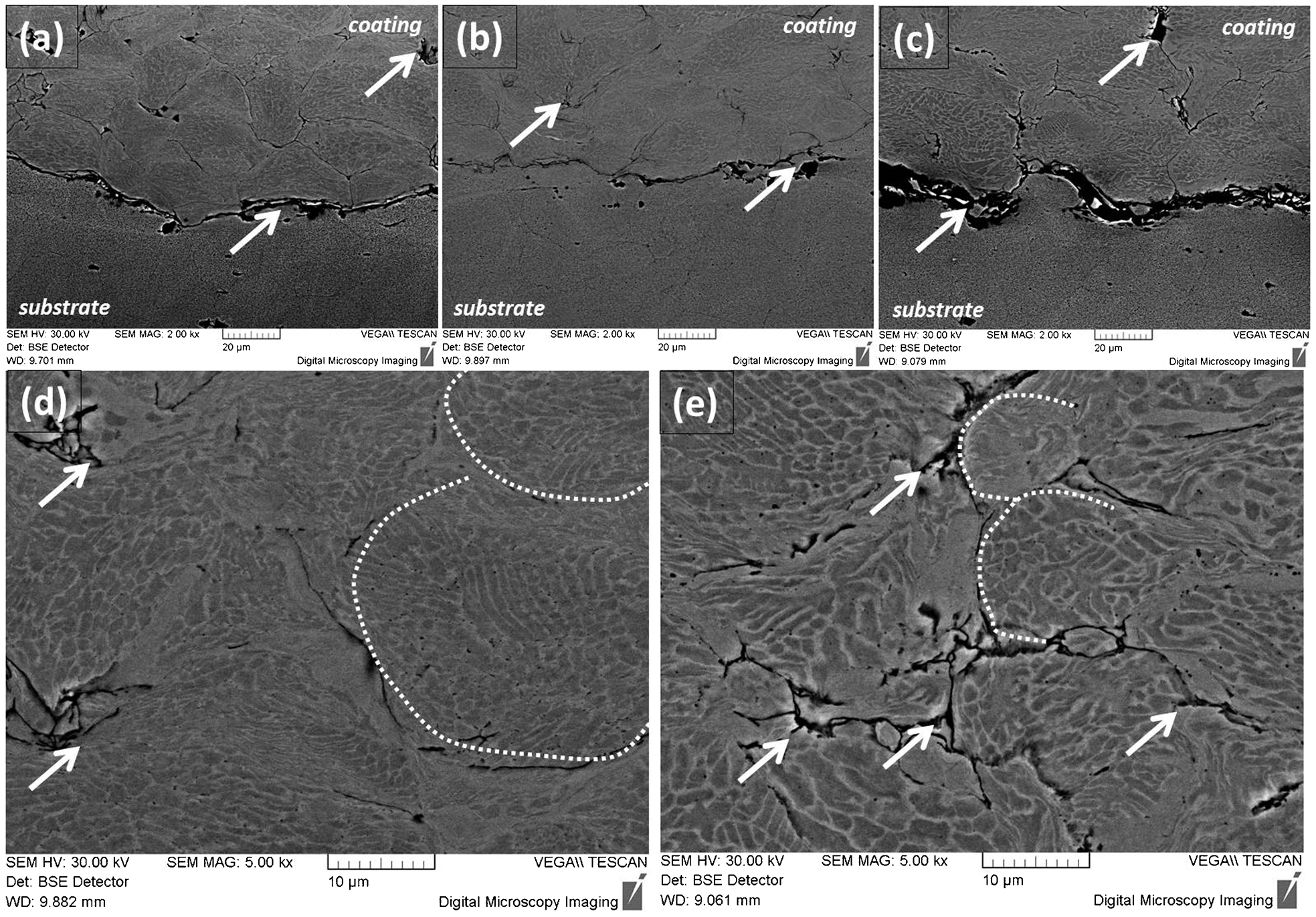
Scanning electron micrograph of cross-sectioned coatings deposited with nitrogen as carrier gas with Kinetiks 4000 and PCS-1000 deposition system; substrate/coating interfaces of a W1, b W2 and c W3; coating microstructure of d W2 and e W3
Concerning the comparison between W4 and W3 coatings, there are macroscopic differences to notice: first of all, the close to zero porosity of W4 as reported in Fig. 3 both at the interface and in the whole cross-section. Then, the plastic deformation at the interface with the substrate that is excellent in case of using helium, very small and isolated porosity and no cracks are observed and good mechanical interlock that is a significant element to determine a good adhesion strength. Plastic deformation is also observed at the particle/particle interface with thin layered compact microstructure due to the severe shear between particles upon impact as highlighted by white arrows in Fig. 5a and b. The bilayered W5 coating showed the characteristics of W3 and W4 coatings as reported above. Figure 5c and d shows a detail of the substrate to bondcoat interface (interface 1) and the interface between bondcoat and topcoat (interface 2) respectively. Interfaces 1 and 2 are also emphasised by the related arrows in Fig. 5c and d. First, the substrate microstructure is totally unaffected by CS deposition as shown in Fig. 5c that is one of the key factor to appreciate CS technology for coating and repair purposes. Then, an interesting element is the observation of the intermediate interface between the bond coat sprayed with He and the top coat sprayed with N2 shown in Fig. 5d, where some porosities and cracks are present in accordance with the growth of coatings sprayed with nitrogen, even if much less severe than at the interface with substrate as reported in W1–W3 coatings. Thus, CS adhesion seems to be more effective on CS coating rather than on bulk substrate of the same material. This can be partially unexpected considering that, set the same material, CS produces hard and stiff coatings exhibiting low plastic deformation behaviour. On the other side, CS leads to high substrate roughness and low surface oxidation that can be effective on promoting mechanical interlocking with subsequent deposited coating, making CS suitable for bond coat deposition. Finally, W4 coating emphasises once again the extremely different characteristics achievable using either helium or nitrogen, and it could represent a promising solution by the point of view of the process design because it combines the adhesion strength requirements with a cost effective process, reducing the consumption of helium.
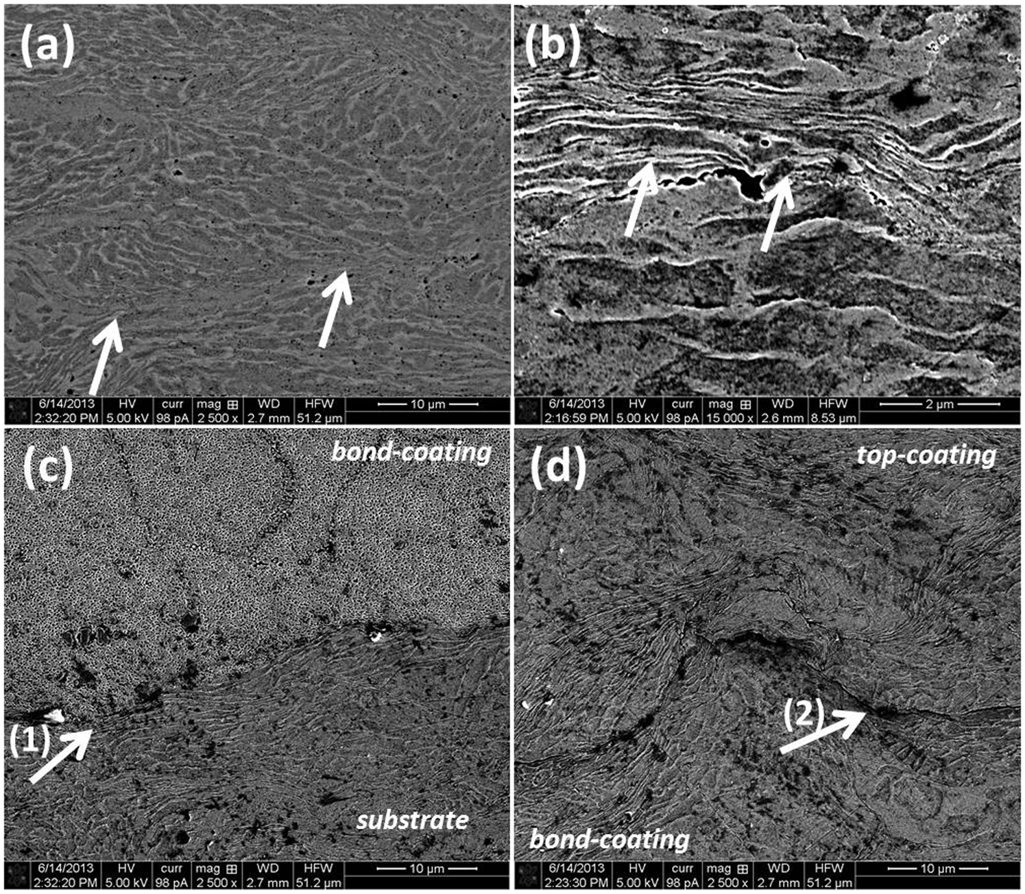
Scanning electron micrograph of cross-sectioned a, b W4 and c, d W5 coatings deposited with helium as carrier gas and PCS-1000 deposition system; detail of coating microstructure to emphasise particle–particle bonding on a helium deposited coating and interfaces between c substrate and bondcoat and d bondcoat and topcoat on W5 sample
Microhardness
The Vickers microhardness of the whole set of samples is reported in Fig. 6. The hardness values obtained with applied load of 25 gf is independent of the deposition conditions and system employed. The highest value is 579±38 HV0·025 reported for W2 samples, while the lowest is 538±41 HV0·025 for W1 sample, as expected due to the low carrier gas temperature used. The indentation imprints have been appositely positioned inside a single particle avoiding the indentation on particle–particle contours. The scattering of the data is quite constant for all samples and ∼7%, revealing a good homogeneity of the hardness when investigated at the ‘microscale’. Despite the high strength of Waspaloy, the hardness increase due to the cold working induced by deposition is noticeable, taking into account that the hardness of the powders is 328±23 HV0·025 and the increment is >40%. On the other hand, the hardness values obtained with applied load of 500 gf behave very differently. All coatings deposited with nitrogen as carrier gas show a drop of the hardness and at the same time a noticeable increase in the scattering of the data; in particular, the hardness of W2 and W3 samples resulted in 489±92 and 457±82 HV0·5 respectively. This drop is due to the low cohesion and particle–particle bonding in agreement with microstructural observation. In fact, the 500 gf imprint is wide enough to cover more particles and a determinate portion of edges and sometime pores. Then, upon indentation, some cohesive failures, crack formation and propagation, local sliding or shearing of particles along the non-bonded particle–particle edges happen as shown by the observation of the imprint shown for sample W3 in Fig. 7. In addition, the coating deposited with helium confirmed the data obtained with low indentation load rather with a further slight increase in the hardness and reduction of the scattering of the data. Furthermore, the imprint shown in Fig. 7 confirmed also the high particle cohesion.
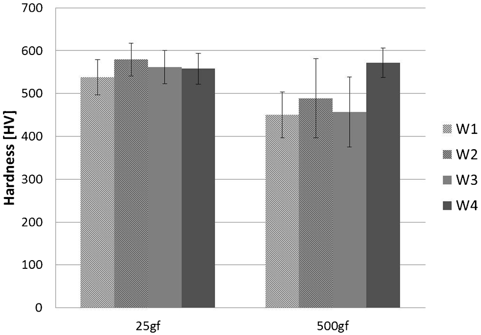
Vickers microhardness of W1–W4 coatings
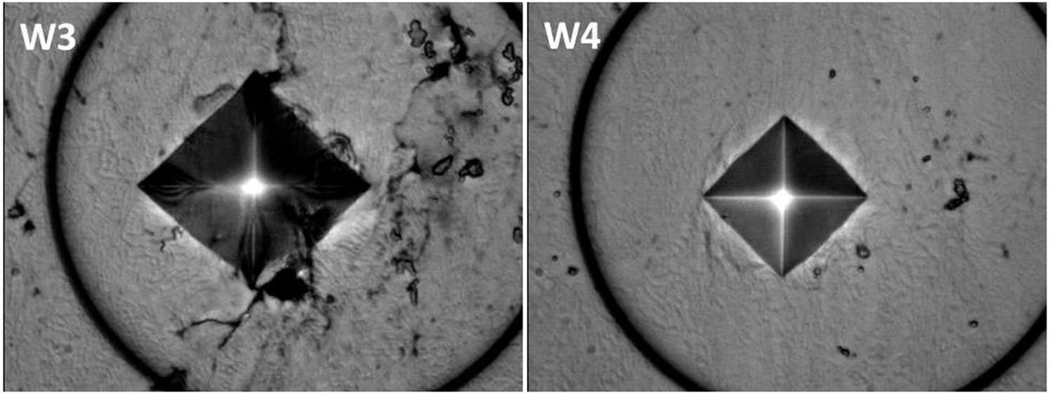
Vickers imprint obtained with 500 gf indentation load on W3 and W4 coatings
Adhesion
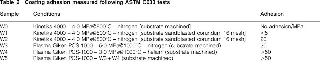
The coating adhesion has been measured according to ASTM-C633 procedure, and the results are summarised in Table 2. W0 coating show no adhesion to the substrate, and in general, the coating grown with Kinetiks 4000 deposition system needs to be deposited onto sand blasted substrates in order to be handled and machined preventing delamination. Then, the adhesion is <∼5 MPa for the coating deposited at 500°C, while it reaches ∼20 MPa in the case of coating deposited at 800°C. On the other hand, sample W3 obtained with nitrogen as carrier gas but with PCS-1000 CS shows adhesion ∼20 MPa onto a machined substrate, which, however, is even too low to be considered acceptable for most application. The samples deposited with helium as carrier gas confirm the microstructural observations and show adhesion strength certainly higher than 50 MPa (the tensile strength of the FM1000 glue is reported to be around this range), which is a significant value for considering this procedure in some selected aeronautical applications. A further feature of interest is the fact that the bilayered W5 specimen exhibits a behaviour, regarding the adhesion to the substrate, close to the fully compact W4 specimen, giving the rupture at the first interface between substrate and bond coat. The second interface between bond coat (He) and top coat (N2) that certainly represents a weak point for the coating is, however, stronger with respect to the first one. Furthermore, this also gives an information about the cohesive strength of nitrogen deposited Waspaloy coating that is still higher than 50 MPa; otherwise, the cohesive rupture of the top coat should be observed.
Coating adhesion measured following ASTM C633 tests
Fractography
Fractography investigation has been performed on samples W2–W4 and is shown in Fig. 8. The results confirm microstructural and mechanical investigations. No significant difference is observed between coatings W2 and W3 obtained with nitrogen as carrier gas respectively with Kinetiks and PCS-1000 systems. The cohesion is relatively low, and the fracture happened along the particle–particle boundaries, revealing scarce cohesive features. On the other side, W4 sample deposited with helium shows a compact microstructure with a noticeable presence of dimples and particle–particle cohesive bonds as highlighted by white arrows in Fig. 8d.
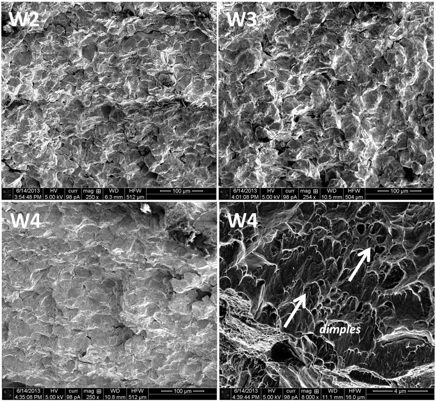
Scanning electron micrographs reporting fractographic investigation of W2, W3 and W4 coatings
Conclusion
The deposition of Waspaloy coatings on Waspaloy substrates has been performed by CS comparing the performances of Sulzer-CGT Kinetiks 4000 and Plasma Giken PCS-1000 deposition systems and comparing the use of nitrogen or helium as carrier gas. The coating microstructure, adhesion and hardness have been characterised.
The coatings deposited using N2/CS show quite compact microstructure with porosity ∼1%. However, particle deformation is limited, coating adhesion is <20 MPa and the weak particle–particle cohesion is pointed out by the crack propagation and coating failure observed close to high load indentation imprints. Kinetiks deposition system produces slightly more compact coatings characterised by a hardness value higher by ∼15 Vickers even if the coating adhesion seems to be more difficult and sand blasting substrate preparation is necessary to have sufficient adhesion to allow handling and machining of the specimen.
The coating deposited using He/CS shows excellent characteristics: very compact microstructure with porosity <0·4% and good particle–particle mechanical interlocking. The interface with the substrate is properly deformed, and the coating adhesion resulted in certainly higher than 50 MPa. Microhardness is ∼560 Vickers and shows no variation as a function of indentation load, confirming a good compactness of the microstructure and particle–particle cohesion.
A promising solution is proposed consisting of the deposition of a bilayered coating composed by a fully compact bond coat realised with helium as carrier gas and a topcoat realised with nitrogen as carrier gas. The microstructure and properties of each layer are in agreement with the related coatings deposited under the same conditions; however, this process allows obtaining high adhesion strength that is one of the main characteristic required for MRO applications with a cost saving process.
Regarding the opportunity to implement the employment of CS for MRO of Waspaloy parts of aeronautic gas turbines, certainly, the performances and characteristics of coatings obtained with helium as carrier gas can be comparable to other thermal spray technologies. However, process costs must be considered carefully due to the well known economic impact of using high amount of helium. Today, CS with nitrogen is considered not yet competitive by the qualitative point of view with current performances obtained with thermal spray. 25 Finally, deposition of bilayer coating with He bond coat and N2 top coat could represent a promising compromise to balance coating and process performances with operating costs and could represent a suitable alternative to other high velocity deposition processes.
Footnotes
Acknowledgements
This work has been carried out within the project LPT Waspaloy Casing Repair co-funded by the P.O. PUGLIA 2007-2013 CONTRATTI DI PROGRAMMA REGIONALI - FE6.102933. The authors would like to thank Alessandro Surpi for technical support and fruitful discussion about coating characterisation.