
Abstract
Plasma electrolytic oxidation (PEO) is a promising and environmentally friendly surface treatment based on electrolytic conversion that forms a protective ceramic oxide coating on light alloys. The PEO coating provides excellent corrosion and wear resistance to the substrate and, as such, is being considered for wider industrial applications on Mg alloys, which are commonly used in aerospace and automotive industries. Several studies have been conducted on the PEO process of conventional Mg alloys, such as AZ and AM series alloys, but to date, little has been reported on rare earth (RE) element containing Mg alloys. In this study, RE elements containing E21 and WE43 Mg alloys were coated using a laboratory scale PEO system. In order to enhance the frictional properties, the surface of PEO coatings was post-treated with MoS2 lubricant. Test results indicated that the PEO coating significantly enhanced the wear resistance of Mg alloys. Further improvement in wear resistance was achieved by the lubricant top layer.
Introduction
Mg and its alloys are widely used in the automotive and aerospace industries owing to their high specific strength and low density, making the parts made of Mg alloys lighter and thus decrease the overall weight of the vehicle. Typical applications using rare earth (RE) containing Mg alloys include transmission casings, helicopter gearbox parts and some parts in motor racing engines such as pistons and cylinder bores. In service conditions, these alloys are subjected not only to corrosion but also mechanical wear. Although RE containing Mg alloys possess good mechanical strength at high temperatures (200–300°C) and exhibit greater corrosion resistance compared to traditional AZ and AM series alloys, their low wear resistance hinders their widespread usage in engineering applications. When parts made of Mg alloys come in contact with harder materials, they preferentially wear out.
Although researchers have mainly focused on investigating the wear behaviour of most commonly used Mg alloys, such as AZ91 1 due to its satisfactory mechanical strength for structural applications, the tribological properties of RE containing Mg alloys have been less reported in the literature.2–8 Nouri et al. 3 investigated the effects of yttrium on wear, corrosion and corrosive wear of as cast Mg–3%Al alloy. It was shown that the addition of yttrium increased the wear resistance of the alloy through the formation of a harder second phase, Al2Y, by attracting Al from the Mg17Al12 phase. An et al. 4 studied the sliding wear behaviour of as cast Mg alloys, namely Mg97Zn1Y2 and AZ91, using pin on disc configuration at different applied loads ranging from 20 up to 380 N. As a consequence of wear tests, the improved tribological property of Mg97Zn1Y2 alloy at high applied load was attributed to the superior thermal stability of the RE containing intermetallic phases, whereas the intermetallic phase Mg17Al12 in AZ91 lost its mechanical strength due to high surface temperatures at high loads, leading to excessive wear damage. In another study by Zafari et al., 7 the effect of 3 wt-% RE addition on the tribological properties of AZ91 alloy was studied at different testing temperatures of 25–250°C and sliding speeds of 0·4 and 1 m s−1. It has been observed that the addition of RE elements decreased the wear rate of AZ91 at higher testing temperatures by the formation of stable oxide layers on the wear surface. Lopez et al. 8 investigated the wear resistance of ZE41A Mg alloy using pin on disc technique and steel as counter body on dry sliding conditions. The authors calculated the wear rates in a sliding velocity range of 0·1–1 m s−1 and in a normal force range of 5–40 N in order to obtain the wear mechanism map. It has been found that the wear rate increases with an increase in applied load and, for most conditions, reduces with an increase in sliding velocity.
Based on the as mentioned test results, it has been observed that Mg alloys have tendency to oxidation, seizure and abrasive wear and lose their mechanical strength especially at high surface temperatures, leading to increased wear rate. From this point of view, the alloying with RE elements provides limited wear resistance. Application of an appropriate surface coating is thus necessary to protect the material from being deteriorated by mechanical wear. Different types of surface modification techniques, including electrochemical plating, gas phase deposition process, conversion coating, anodising and laser surface alloying, are applied to achieve the desired wear and corrosion resistance of Mg alloys. In addition to these techniques, a relatively new technique of plasma electrolytic oxidation (PEO) has been used to coat Mg and its alloys in the last decade. In this technique, the plasma is discharged by an external power source in a low concentration alkaline electrolyte near the surface of the workpiece, which acts as the anode of the system. The microscopic plasma generations cause partial short term surface melting and consequently the formation of a highly adherent and inert oxide ceramic layer. The mechanism of oxide layer formation during the PEO process represents very complex combinations of oxide growth with subsequent fusing and recrystallisation of the oxide film and also involves partial substrate metal dissolution at microscopic levels. The resulting oxidation of the alloy surface can also include some elemental co-deposition from the electrolyte, creating a ceramic layer that contains both crystalline and amorphous phases.
Since PEO coatings provide great enhancement in the corrosion resistance of Mg alloys, most of the studies in the literature focussed on the investigation of the electrochemical behaviour of the coated substrates. Only limited work has paid their attention to the mechanical properties and wear behaviour of PEO-coated Mg alloys.9–12 In this study, two most commonly used aerospace grade alloys, namely Elektron21 (E21) and WE43, were coated using the PEO process in order to enhance their wear resistance. A solid lubricant layer was also applied on PEO coated alloys to improve their frictional properties. Scratch and dry sliding wear tests were undertaken to assess the adhesion strength of the coating to the substrate and wear properties respectively.
Experimental
Specimen preparation
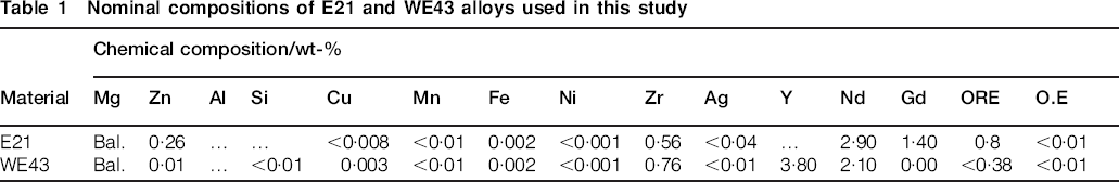
The REs containing E21 (AMS 4429) and WE43 (AMS 4427) cast plates in T6 condition were supplied by Magnesium Elektron Ltd (Manchester, England). The nominal compositions of these alloys are given in Table 1. For the preparation of coatings, test specimens were obtained by cutting off the supplied plates into 25×25×5 mm size. The specimens were abraded using 1200 grits SiC papers, subsequently cleaned in an ultrasonic bath with ethanol and finally rinsed in distilled water.
Nominal compositions of E21 and WE43 alloys used in this study
Plasma electrolytic oxidation process
The PEO coatings were produced using a commercial version of the Keronite G2 PEO system with a 25 kW pulsed bipolar alternating current power supply. The alkaline electrolyte composed of Na2SiO3.5H2O (5 g l−1), Na3PO4.12H2O (2 g l−1), KOH (3 g l−1) and KF (2 g l−1) was used for coating the specimen, which was mounted on an anode copper bar with appropriate jigging equipment. Perforated sheet in 316 grade stainless steel was used as cathode in the PEO process. The coating treatment was conducted for 20 min in constant current mode with an initial current density of 10 A dm−2. During the PEO process, the variation of voltage was recorded via computer. After the PEO process, a MoS2 friction modifier was applied on some specimens with the spray method to investigate the effect of solid lubrication on the wear behaviour of the coated specimens.
Optical emission spectroscopy
A schematic diagram of the experimental set-up is shown in Fig. 1. The optical emissions generated by the plasma discharges were collected with a fused silica 74-UV collimating lens (Ø5 mm), which is screwed on the end of the 600 μm diameter fibre optic cable leading to the entrance slits of the spectrometer system. The distance between the specimen and the collimating lens was fixed at 30 mm. The optical emission light was transmitted through the fibre optic cable and fed to an Ocean Optics LIBS2500 Plus system, which included three channel slots, each of which covers a certain wavelength region (with a full range of 200–1019 nm). Each channel consisting of an Ocean Optics HR2000+ spectrometer can be operated separately or together. The spectrometer that has a bandwidth of 580–1019 nm consists of a Sony ILX511b 2048-pixel charge coupled device linear sensor with a grating of 600 lines blazed at 750 nm and a 25 μm slit. The other two spectrometers operating at 200–419 and 400–604 nm bandwidths have a Sony ILX511b 2048-pixel charge coupled device linear sensor with a grating of 1200 lines and a 10 μm slit. The emission intensity of the plasma species at specific wavelength was monitored as a function of time using the optical emission spectroscopy system. The full range of spectrum was also recorded at selected time intervals.
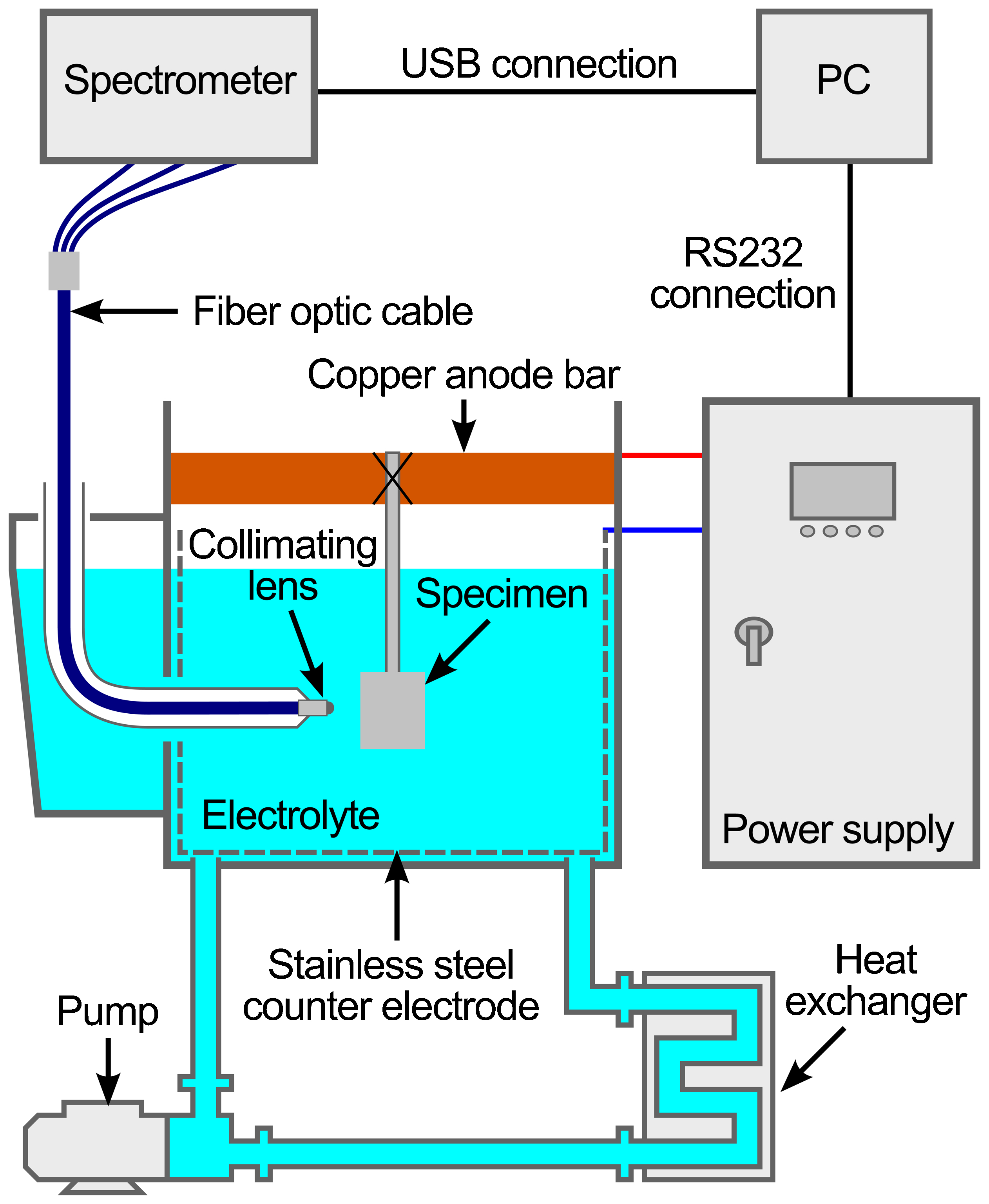
Schematic diagram of experimental set-up used for coating E21 and WE43 alloys
Coating characterisation
The structural and elemental analyses of PEO coatings were performed using a JEOL 6060 SEM equipped with energy dispersive X-ray spectroscopy attachment. The phase composition of PEO coatings was determined by a Rigaku X-ray diffractometer with Cu Kα radiation as excitation source.
Scratch test
Adhesion of the coatings was evaluated using a CSM microscratch tester. In this test, the load on a diamond Rockwell indenter with a tip radius of 100 μm was linearly increased from 0·2 to 30 N at a normal loading speed of 60 N min−1 as the diamond tip is drawn across the surface of the coating. After the test, the scratch on the coating surface was examined under an optical microscope and SEM to determine the point at which the coating had chipped off. Then, the critical load values were determined using supplementary data graphics, including acoustic emission, penetration depth and frictional force.
Wear test
The wear behaviour of the coatings was examined in dry condition with ball on plate test configuration against alumina ball (Al2O3, ∅6 mm). Dry sliding wear test was performed at 5 and 10 N normal loads by applying a fixed sliding velocity of 1·6 cm s−1. The stroke length and total distance were 8 mm and 50 m respectively. After the wear test, the wear mechanism was investigated using SEM on bare and PEO coated substrates. The material volume loss was estimated from the wear track profile using an Ambios Technology XP-2 high resolution surface profilometer.
Results and discussion
Structural examination
The X-ray diffraction (XRD) patterns given in Fig. 2 indicated that the coatings on both E21 and WE43 alloys have similar phase composition. The coatings were composed of periclase (MgO) and forsterite (Mg2SiO4), and some peaks corresponding to the Mg substrate were also observed in the XRD results due to the penetration of X-rays into the substrate alloy through the micropores present in the microstructure of the PEO coating.
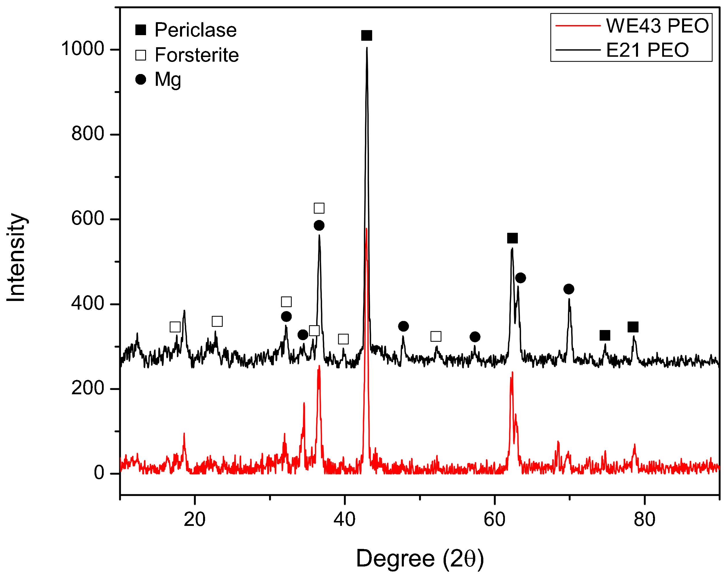
X-ray diffraction patterns of PEO coatings on E21 and WE43 alloys
The surface and cross-sectional SEM images of PEO coating on E21 alloy are shown in Fig. 3. Because the PEO coatings on both E21 and WE43 alloys had nearly similar microstructure, only the SEM images of the coating on E21 alloy have been given to represent the surface morphology and cross-sectional view. The average thickness values of PEO coatings on E21 and WE43 were determined using cross-sectional SEM images and calculated as 26·6±4·2 and 26·5±3·1 μm respectively. It has been observed that the MoS2 top coat has been well adhered to the coating surface and formed a continuous layer with an average thickness of 7·5±1·5 μm. As seen in Fig. 3a, the surface of the coating contains a lot of micropores that are the end points of plasma discharge channels whereby the molten oxide products are transferred to the surface and solidified when coming in contact with the electrolyte. Owing to the high thermal gradient between the core of discharge channel and its surrounding, rapid heating and cooling of the coating material caused microcracks around the pores. The closed micropores seen on the cross-section of the coating are the result of entrapped gas bubbles, which are formed by the oxygen evolution taking place on the anode surface.
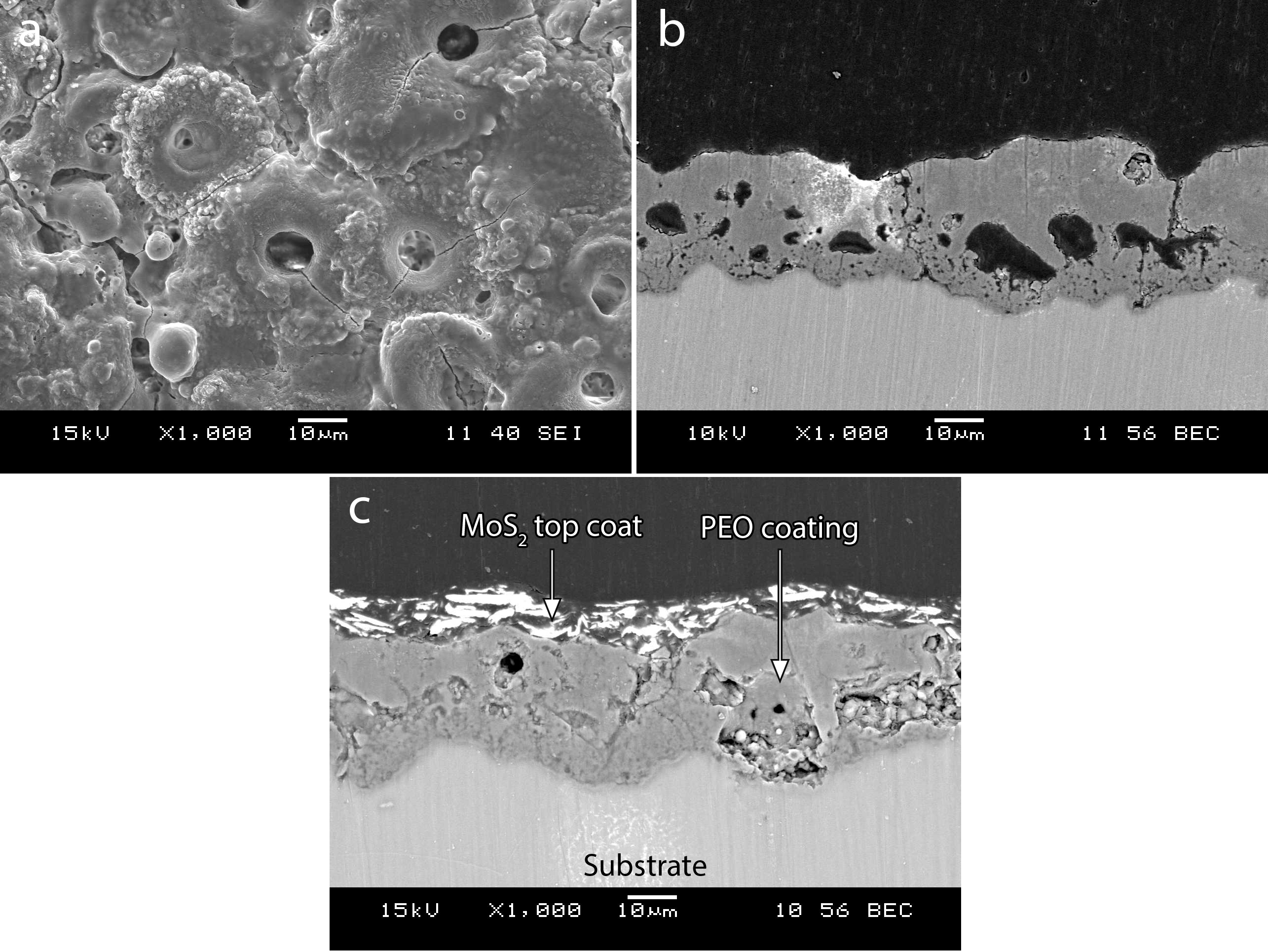
a surface and b, c cross-sectional SEM images of PEO coating on E21 alloy
Plasma characterisation
The variation of voltage and OES signal during the PEO process of E21 alloy is shown in Fig. 4. The evolution of plasma discharges was followed using the spectral line of neutral Na element due to its higher intensity value compared to the Mg element present in the substrate alloy. Although both emission lines corresponding to neutral Na and Mg elements follow nearly the same path over the PEO process, it was easier to distinguish different stages when the emission spectra of neutral Na element were used.
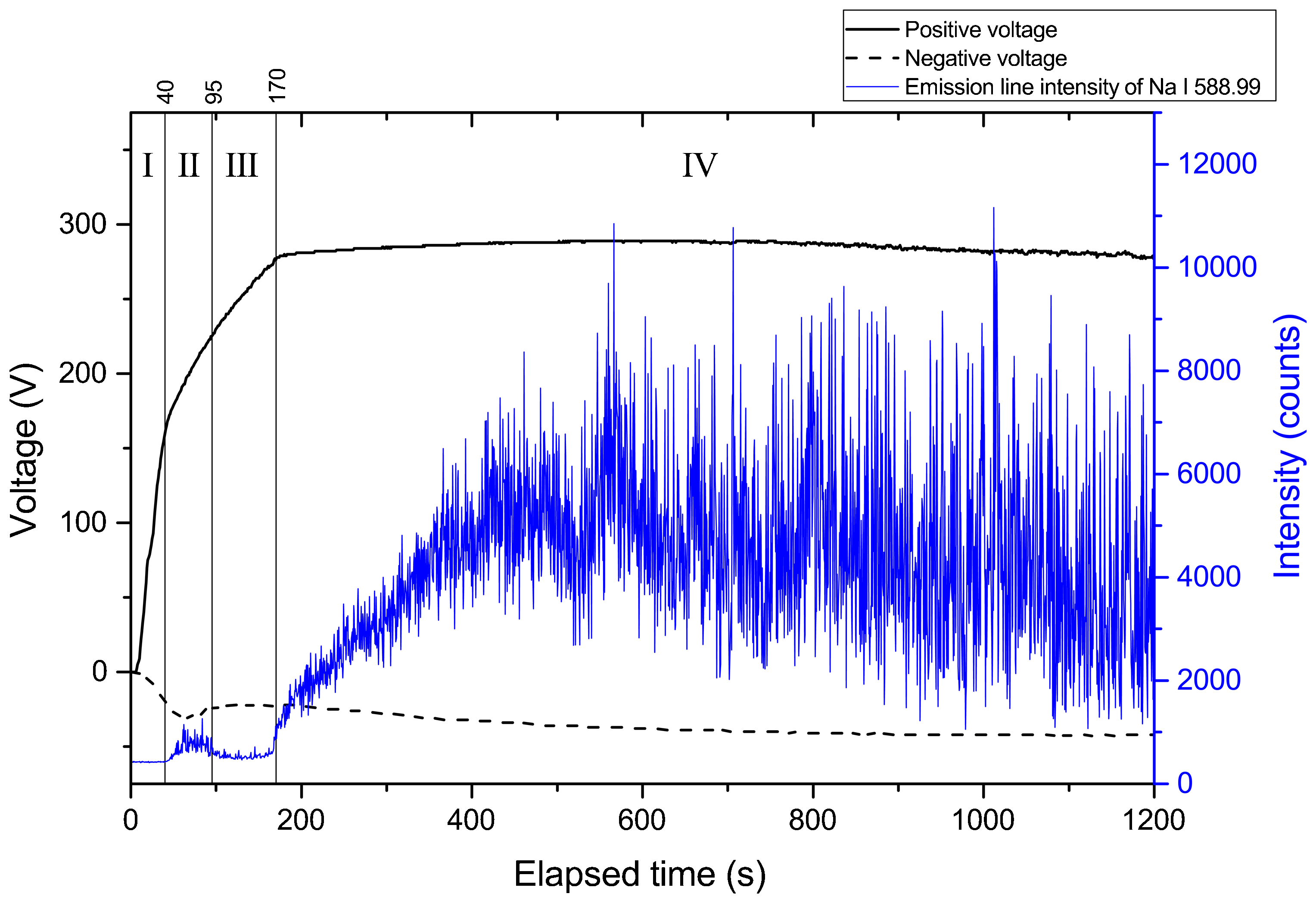
Variation of voltage and OES signal during PEO process of E21 alloy
Depending on the variation of OES signals and voltage over coating treatment, four stages can be identified. In the initial stage of the PEO process, the voltage rapidly increased, forming an anodic oxide film on the surface of the substrate alloy. During this stage, there was no variation in the OES signals since the dielectric breakdown of oxide film has not been reached yet. After ∼40 s, the voltage passed the critical point at which the sparks began to appear on the substrate alloy (Fig. 5) due to dielectric breakdown phenomenon and then got into the second stage, where the slope of the voltage–time curve reduced. These sparks covered the entire surface in a short amount of time, and the size and intensity of plasma discharges increased in the next 15 s, as seen in the optical images. By the end of the second stage, plasma discharges evolved into less powerful and smaller sparks as in the beginning of the first stage. After ∼95 s, the intensity of OES signals decreased and remained nearly constant until the end of the third stage. When the voltage reached its maximum value at the end of the third stage, the emission line intensity began to increase again, indicative of the formation of more powerful and energetic microarcs. Although the voltage remained constant during the fourth stage, there have been large oscillations in the emission line intensity. These oscillations are related to the arc discharges, which are more powerful and larger than the microarc discharges.
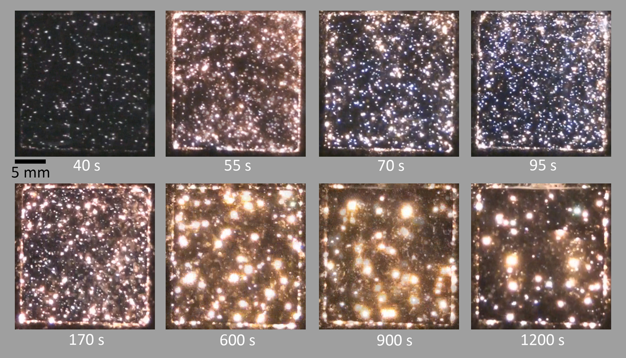
Photographs of plasma discharges formed on E21 alloy
The optical emission spectra recorded simultaneously in different wavelength ranges are shown in Fig. 6. Since the microarc discharges are generated on the anode surface randomly during the period of anodic half cycle, an integrated time approach was used to collect the emission spectra of plasma discharges. Identification of spectral lines was carried out using the database of Micropack Specline software and the NIST atomic spectra database. 13 Intense emission lines corresponding to Na, K and O (from electrolyte) and Mg (from the substrate alloy) were observed. Hα and Hβ Balmer lines were also detected in the broad spectrum.
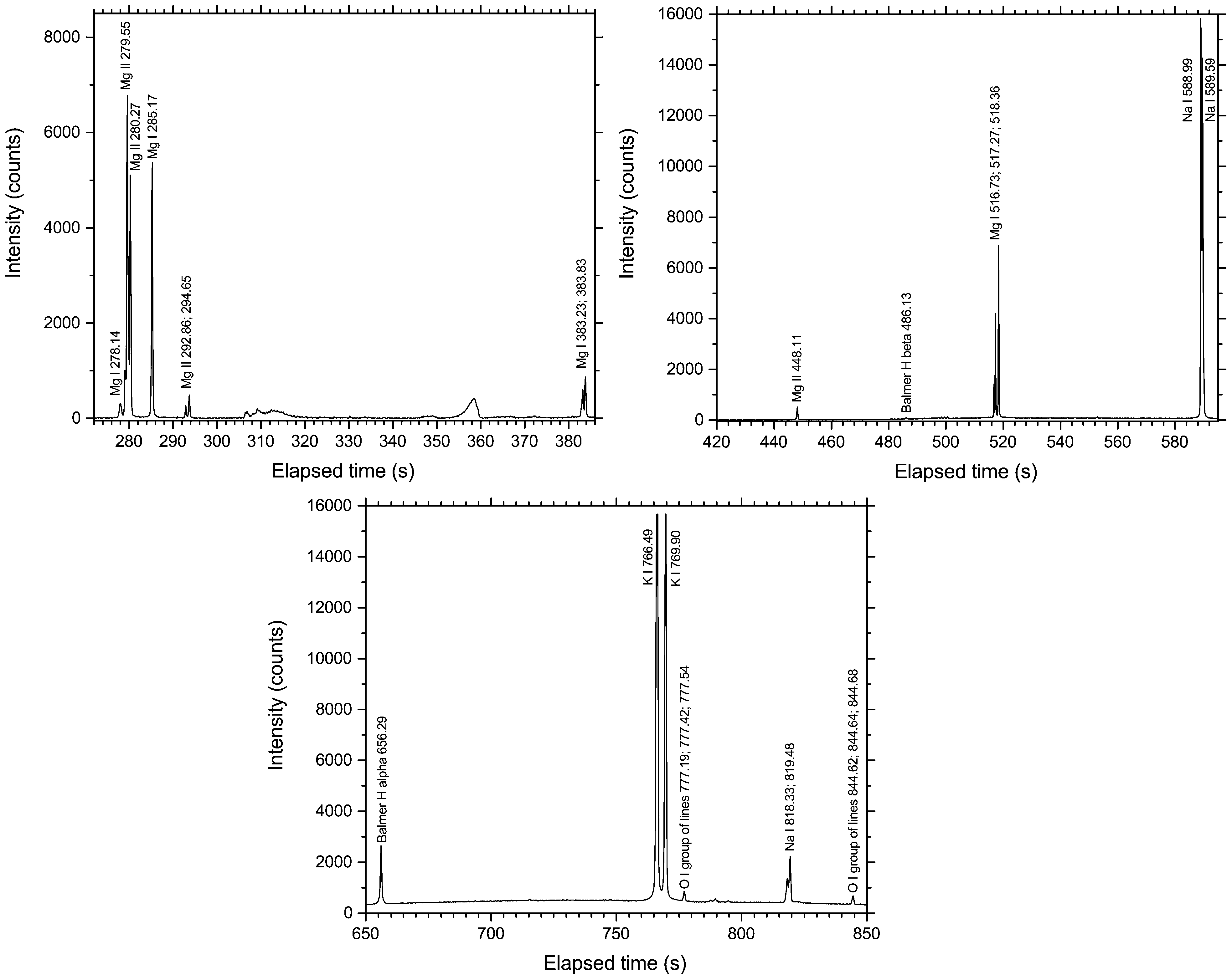
Optical emission spectra recorded simultaneously in different wavelength ranges during PEO treatment of E21 alloy
Scratch test
Supplementary data graphs recorded during scratch test and SEM images of scratches on the coated E21 alloy are given in Figs. 7 and 8 respectively. The critical load value at which the coating removed from the substrate is indicated as a vertical line on the supplementary data graphs. For the PEO coating without top coat, the friction force increased rapidly due to the removal of coating at the critical load and the subsequent establishment of diamond on the metal contact, resulting in large fluctuations in acoustic emission and friction force values. It has been observed that the coatings on both E21 and WE43 alloys have nearly similar critical load values. Application of MoS2 top coat increased the critical load value of the PEO coating nearly threefold. This can be related to the solid lubrication property of the top coat, which adhered to the surface firmly and decreased the shear stresses generated by the moving stylus. As seen in Fig. 8a, the compressive and shear stresses applied by the moving diamond stylus caused microfracture of the coating at first, then adhesive failure occurred at the critical load value. For the coating with top coat, the solid lubricant remained on the surface in the initial stage of the scratch test and retarded the adhesive failure of the PEO coating. After a certain scratch distance, the solid lubricant layer was completely removed, exposing the PEO coating underneath. At this point, the coating fractured due to its brittle nature, and adhesive failure of the coating took place.
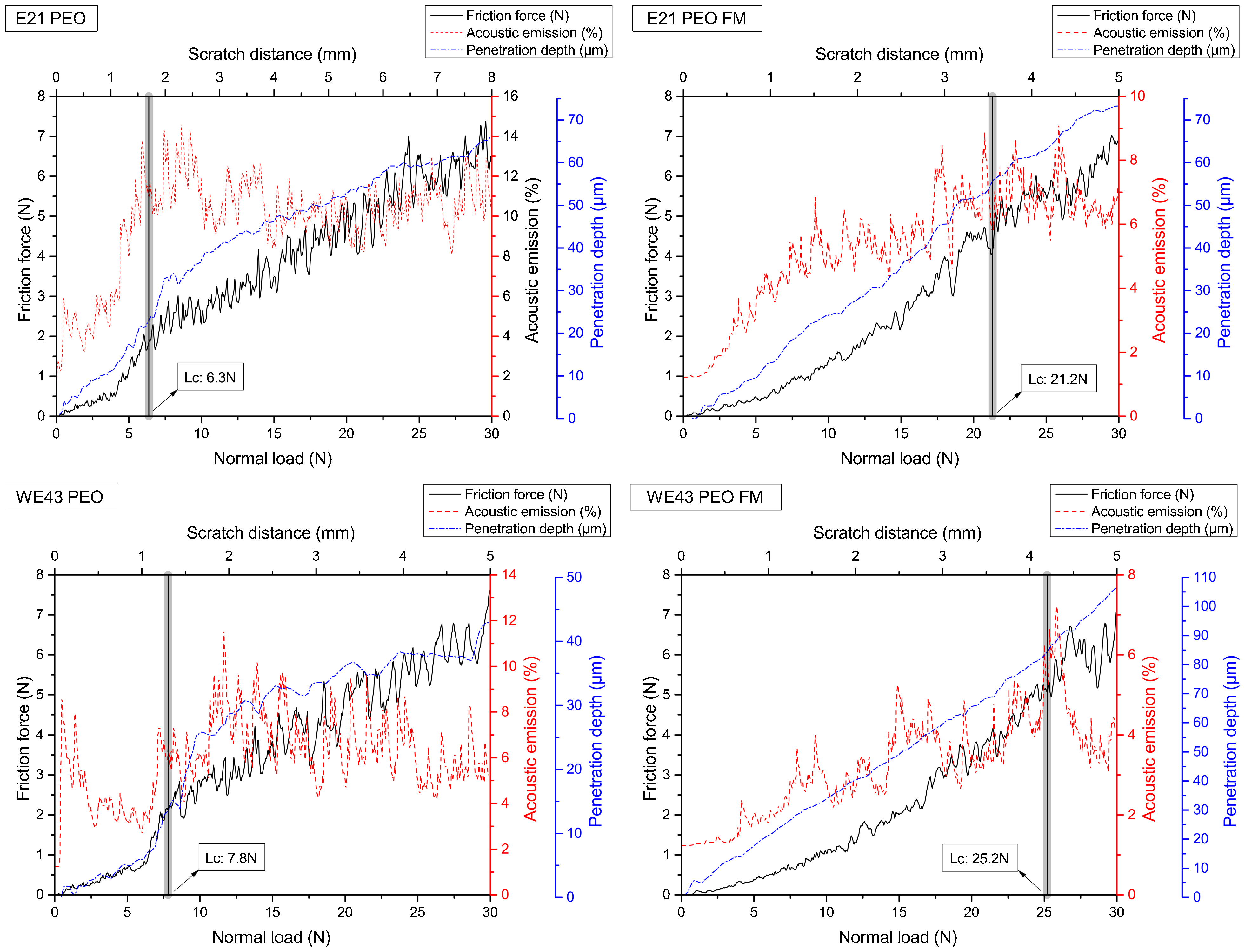
Supplementary data graphs showing variation of acoustic emission, friction force and penetration depth during scratch test of E21 and WE43 alloys
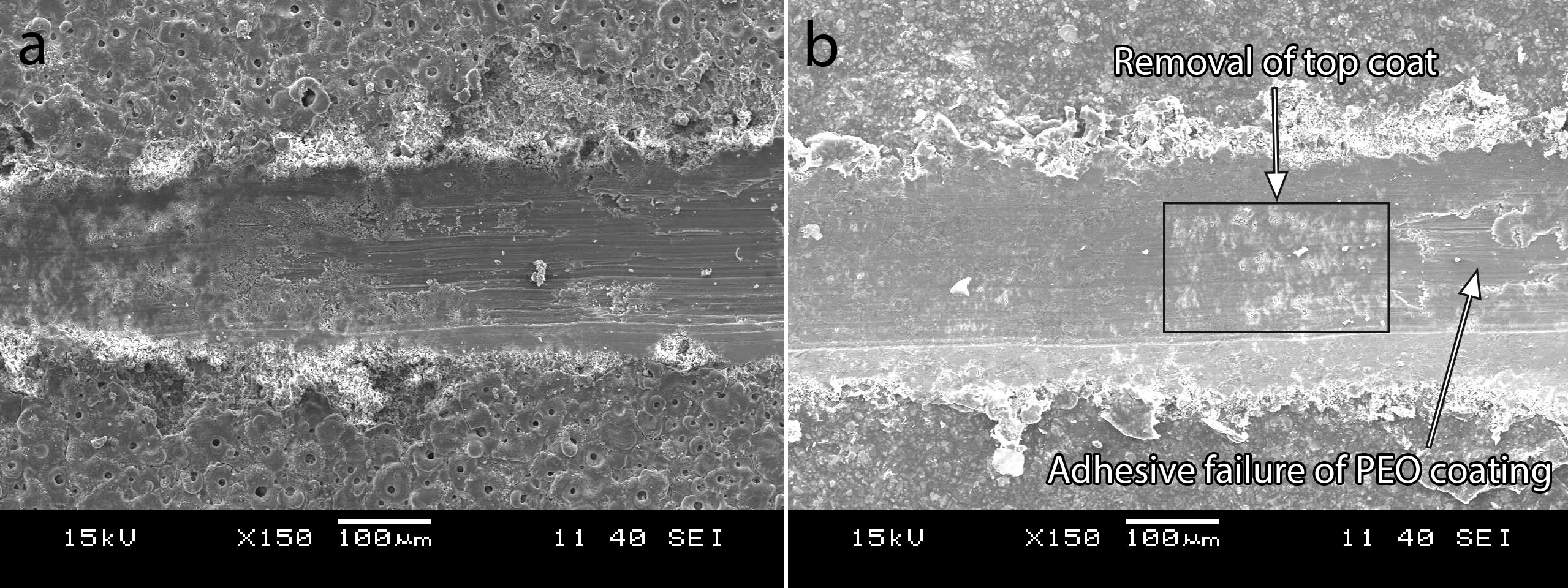
Images (SEM) of scratches on PEO coated E21 alloy a without top coat and b with top coat
Wear test
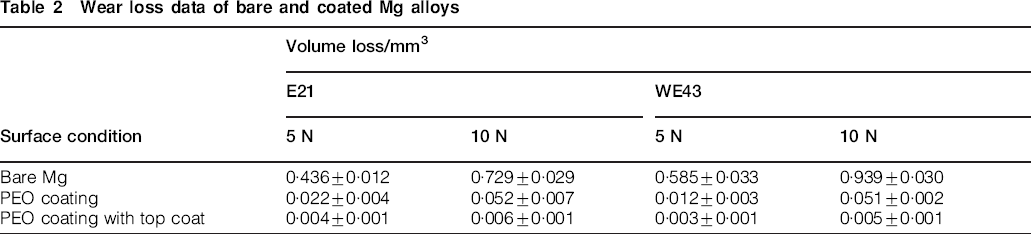
The wear loss data of the bare and coated Mg alloys are given in Table 2. As seen in the table, the PEO coated Mg alloys showed as much as 50 times lower volume loss than that of bare Mg alloy. This indicates that the PEO coating greatly improves the wear resistance of substrate alloys. Further improvement in the wear resistance of substrate alloys was achieved by application of top coat on the PEO coating. The solid lubricant layer decreased the volume loss of the PEO coated Mg alloy nearly 10-fold.
Wear loss data of bare and coated Mg alloys
The wear track images and wear profiles of the tested E21 alloy with different surface treatments are shown in Figs. 9 and 10 respectively. It has been observed that the ceramic ball, which is much harder than the Mg alloy, caused ploughing on the surface, indicative of abrasive wear mechanism (Fig. 9a and b). As seen in Fig. 10, the abrasive wear of Mg alloy caused a deeper wear profile, indicating higher wear loss compared to PEO coating with and without a top coat. In case of the PEO coating without top coat, the surface irregularities were polished by the ceramic ball, and the shear stresses generated by sliding motion caused fractured segments that were then partially removed from the surface. For the PEO coating with top coat, the solid lubricant layer remained in the wear track and protected the subsequent oxide layer from excessive wear damage.
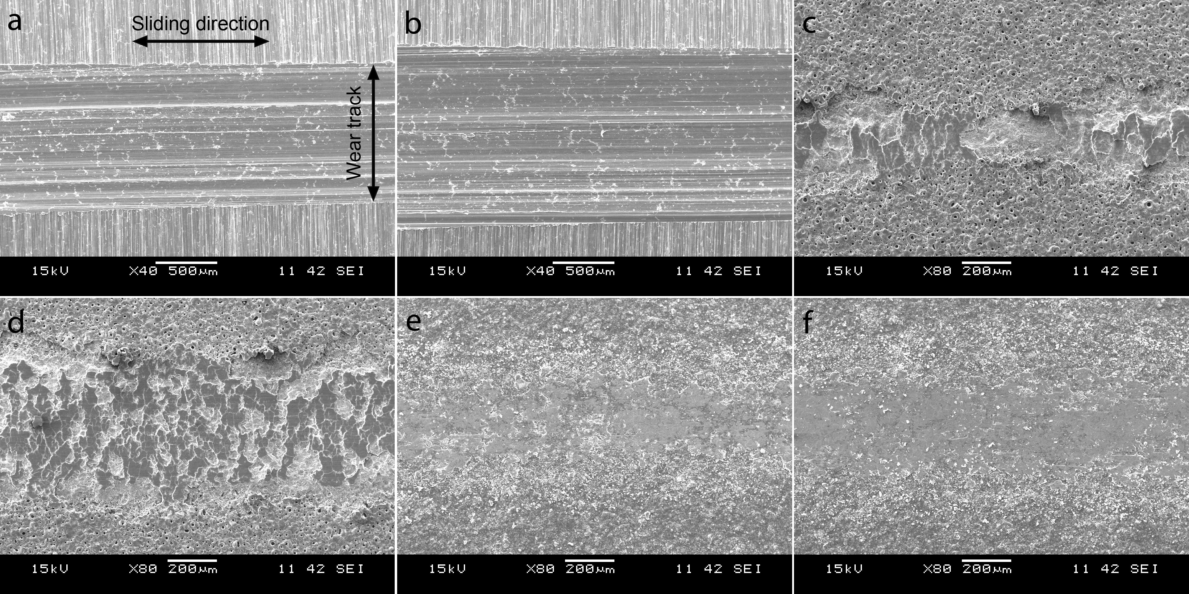
Wear track images of a, b bare, c, d PEO coated and e, f PEO coated and top coat applied E21 alloy: applied loads are a, c, e 5 N and b, d, f 10 N
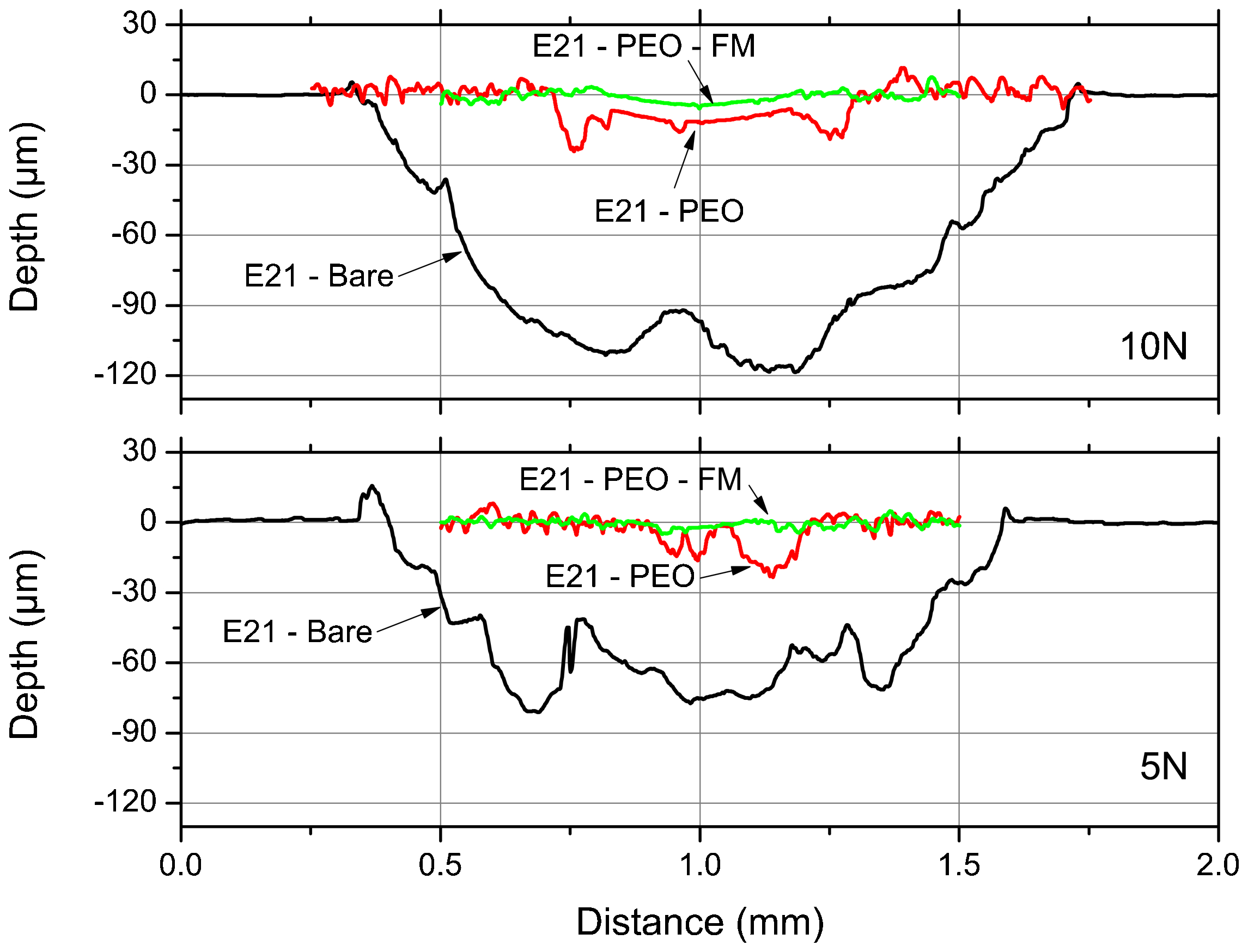
Wear profiles obtained using Ambios Technology XP-2 high resolution surface profilometer
The variation of friction coefficient during sliding wear is shown in Fig. 11. As seen in the graph, the friction coefficient of bare and PEO coated Mg alloy increased with increasing total distance, and large fluctuations especially for bare Mg alloy were observed in the coefficient values. Application of the top coat decreased the friction coefficient substantially.
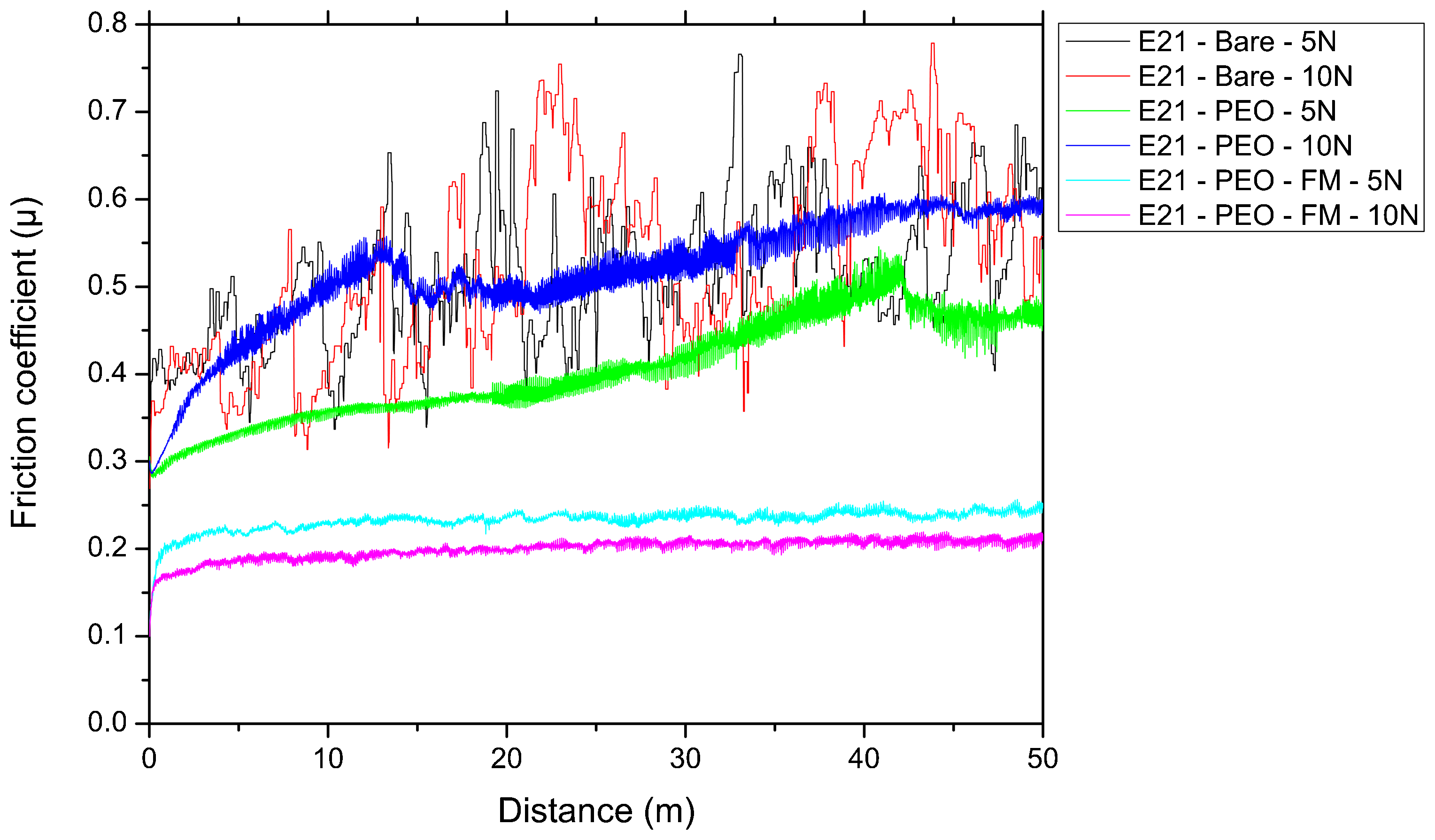
Variation of friction coefficient during sliding wear test
Conclusion
The mechanical and tribological properties of PEO coated E21 and WE43 Mg alloys were investigated, and the following conclusions were drawn.
During the PEO process, four different stages according to the variation of emission line intensity and voltage were identified. Intense emission lines corresponding to Na, K and O (from electrolyte) and Mg (from the substrate alloy) were observed. While the plasma discharges appeared less intense and small in the initial stage, their size and intensity increased by the end of the PEO process, turning into powerful arcs.
The solid lubricant layer on the PEO coating adhered to the surface firmly and decreased the shear stresses generated by the moving stylus during scratch test. Consequently, the critical load value at which the coating removed from the surface increased.
The PEO coating greatly improved the wear resistance of the substrate alloys. Further improvement in the wear resistance was achieved by reducing the friction coefficient value with application of top coat. Abrasive wear mechanism was observed during sliding wear tests of the bare Mg alloys.