
Abstract
The centrifugal pumps made of grey cast iron deployed in mining conditions encounter severe erosion and corrosion problems causing sudden failures. To combat this, the thermal spray ‘high velocity oxyfuel’ (HVOF) process was selected to provide a cermet coating, namely, WC–Co–Cr–Ni. After design investigation on coatings, erosion and corrosion experiments were conducted and characterisation studies involving microstructure, surface morphology and energy dispersive X-ray fluorescence analysis were made. The operating parameters on the different sections of impact volute surface were assessed and accordingly, the coating thickness was designed scientifically for maximum impact loads and minimum corrosion failures. The life of the coated pump casings has been improved up to 12 times by optimising the coating thickness.
Introduction
The highly acidic medium with high velocities of flow media results in faster erosion/corrosion rates. This is further accelerated with presence of abrasive erodent particles in media. 1 The mechanisms of degradation in these environs are being studied as there are many applications in mining/mineral processing industries. The evaluation of mechanisms of corrosion and erosion corrosion in the above environments plays a vital role in finding feasible solutions in surface engineering treatments with specific methods such as surface hardening, carburising (phase change at surface with additives) and coating process, all of which involve producing a surface layer of a specific material with different wear properties. Without understanding the mechanisms in such environments, the solutions are severe. The present research attempts to establish mechanisms of corrosion and erosion–corrosion in highly acidic and high velocity systems through series of experiments designed to study the effectiveness of coatings in prevention of erosion/corrosion. The dominance of high velocity oxyfuel (HVOF) process for such environment is established with appropriate coating parameters such as coating thickness to withstand stress caused by both corrosion and high erosion rates also established. When corrosion rates are minimised along with safe/failure free coatings, the wear rates shall be least, increasing the life of surfaces.
Erosion in flow systems
The wear rate of the volute section is affected directly by the slurry concentration, the size of erodent and velocity of the media.2,3 In the case of turbulent flow (the Reynolds number RN: ∼30 250) and higher surface roughness Ra (40–60 μm), the local cavitations become more pronounced. These local cavitations caused by the growth and explosion of bubbles release shock waves in narrow regions at temperature of about 800°C and pressure of 405300 kPa 4 creating a patch of craters and pinnacles on surfaces. Cavitation accelerates the electrochemical corrosion with strong synergism between mechanical and electrochemical corrosion factors. 5 It is experimentally proven that in mining slurry environment, mass loss due to wear increases with increasing exposure time. However, the effective wear rate is initially higher, but subsides at later stages. 6 Since erosion is a complex phenomenon involving flow parameters and stresses combined with microstructures of materials, it needs competent evaluation for better understanding. 7 Wear by slurry abrasion occurs in extruders, slurry pumps and pipes carrying slurry of minerals and ores in mineral processing industries. The life of components used under slurry abrasion conditions is governed by parameters such as abrasive particles in slurry and material properties. 8 Corrosion resistance and corrosion fatigue resistance of WC–Co–Ni–Cr coatings are found to be more than the WC–Co coatings. The addition of chromium to the matrix greatly enhanced the corrosion resistance of the coating. 9
Erosion–corrosion
Erosion–corrosion increases with flow velocity, particle size and sand content. Rate of erosion–corrosion depends on amorphous phase contents, porosities and hardness. Erosion–corrosion process is mechanically dominated and attack arises from defects in coatings. The HVOF coatings are potential candidates to improve erosion–corrosion behaviour of marine pumps. 10 The rationale behind the selection of erosion resistance surfaces for fluid handling equipment highlights the complexities encountered when these surfaces are exposed to environments containing sand particles, which causes local cavitation in a corrosive medium. 11 As the flow parameters dominate at high velocities, erosion becomes significant and the coatings need to be ablation resistant. Celotta et al. have established that WC showed better erosion resistance than SiN, SiC, etc. 12 For the same WC–Co content, WC–Ni–Co–Cr alloys present higher wear resistance than those based on WC–Co, despite their lower hardness due to the higher oxidation resistance of the Ni–Co–Cr binder phase. This is likely due to the higher oxidation resistance of Ni–Cr alloys compared to those based on cobalt. 13
HVOF coatings
HVOF coatings14,15 have proved to possess better corrosion/erosion resistance than D-Gun coatings. WC coatings with metallic binders processed through HVOF provide high wear and/or corrosion resistance coatings. HVOF process produces dense coatings with low porosity and high hardness. 16 The HVOF spraying leads to a high retention of WC in the coating matrix accompanied with lower porosity. Polarisation and electrochemical impedance spectroscopy studies on both uncoated substrates and WC–Ni and WC–Co coated samples on mild steel substrate immersed in 3% NaCl solution reveal that WC–Ni coating with a lower porosity, serve as a better barrier and effectively prevent corrosion attack. Addition of nickel as metallic binder in the WC coating was found to have a better corrosion resistance than cobalt in the WC coating.17-19
Other influencing factors
The presence of Cl− ions in the mine water tends to accelerate the pitting due to fast depleting passive films similar to highly corrosive sulphates ions. 20 In a chloride environment, the local pH on iron is non-uniform and decreases at anode site with high chloride content and approaches to 1·5 in less than 150 000 s 21 (∼41·7 h). Malka et al. 22 reported that the rate of erosion–corrosion is about three to four times more than that of erosion rate alone. The synergism of erosion–corrosion increased from 42 to 66·5 and 78 to 85%, when velocity was increased from 5 to 10 m s−1. 23 To combat erosion in pipelines and pumps where the degradation is caused by a combination of sand particles and water, cermet based coatings are being increasingly used. The interactions between the processes of erosion and corrosion have only been evaluated for a limited range of parameters, though in reality erosion–corrosion occurs over a wide range of variables. 24
The exposure of substrate to the water should be least for minimising corrosion and for this porosity has to be kept close to zero. Inspection of failed components revealed that the failure process is corrosion initiated and then erosion dominant corrosion initiated layers are removed faster due to combination of factors like micro pitting, local cavitations and impulsive jet of water with sand erodents.25-29 It was observed that WC–Co–Cr cermet coating deposited with fine grained WC exhibits higher slurry erosion resistance under all testing conditions as compared to conventional cermet coating.
Experimental procedure
Based on the above criteria, test coupons of dimensions 50×30×10 mm were coated with WC–Co–Cr–Ni for characterisation studies. Two samples each of coatings with thicknesses of 400, 350, 300 and 250 μm were tested for mechanical properties, surface roughness (Ra) and porosity of coating. The composition of volute material analysed through Optical Emission Spectrometer, Spectro Maxx LMF06 (Spectro Maxx, Germany, 2010) were 4·35C–3·02Si–0·667Mn–0·133S–0·107P–0·0335Cr–0·0169Ni–0·0105Mo–0·0110V. The volutes made of FG 260 2–2·5%Ni Grade Cast Iron have stable crystal structure and absorb vibrations possessing good wear resistance. 30
HVOF coating process
The wear and corrosion rates of coatings are influenced mainly by the coating composition, microstructure, defect level and adhesion. The particle sizes of the coating material directly influence the corrosion behaviour and wear resistance of the coating. 31 The bonding mechanisms between WC–Co–Cr–Ni and substrates are more robust and high in HVOF process for higher velocity and stress condition. 32 To withstand cyclic stresses, HVOF sprayed WC–Co coating with good fatigue strength is recommended. Decarburisation of WC during spraying can be prevented by using duplex cobalt coated powder. The HVOF spraying process is chosen as it results in coatings with aforementioned properties. The substrate areas of casings to be coated are also preheated up to 250°C. The coatings were carried out in a ‘HIJET-9610 system’ (MECL India 2008) with ‘KUKA’ robotics arm fitted with HIPO JET 2700 spray gun with appropriate powder mixing units.
Powder parameters and effects
The coating of 84WC–10Co–4Cr–2Ni was carried out by HVOF process in which the mixture of powder fuel and oxygen is accelerated with a speed of around 330 m s−1 at a temperature of 2300°C and sprayed on the surface to be coated. Chivavibul and Watanabe 33 had reported that a Co content of 8–12% in a WC–Co matrix would result in hardness of 1000 VHN and fracture toughness of 400 MPa m1/2. The powder size used range from 10–40 μm. Powders with narrow particle size distributions gave coatings of higher quality than powders with wider particle size distributions. A reduction of the heat input during spraying reduced the degree of WC decomposition and improved the coating properties when the spray powder contained a large fraction of small particles. 34
Erosion tests
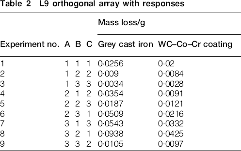
The erosion tests were conducted using water jet erosion tester TR 401-DUCOM (DUCOM, India, 2009) designed as per ASTM standard G73, as shown in the Fig. 1. The surfaces and edges of the cast test specimens of size 50×25×10 mm were polished and ground, to remove oxide scales and dirt, using standard metallographic techniques. The testing parameters as shown in the Table 1 were varied according to design matrix of L9 orthogonal array, for each test. Silica particles of mesh size 600 μm were used as erodent. The weight of each sample was measured, before and after the test, to find out the difference in the mass loss. Weight measurements were made with a precision up to 0·0001 g. A minimum of three tests was conducted on each sample. In Table 2, the observed mass loss as a response for nine set of varying test conditions were shown.
Test parameters for erosion studies
L9 orthogonal array with responses
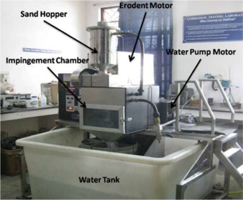
Water jet erosion testing set-up
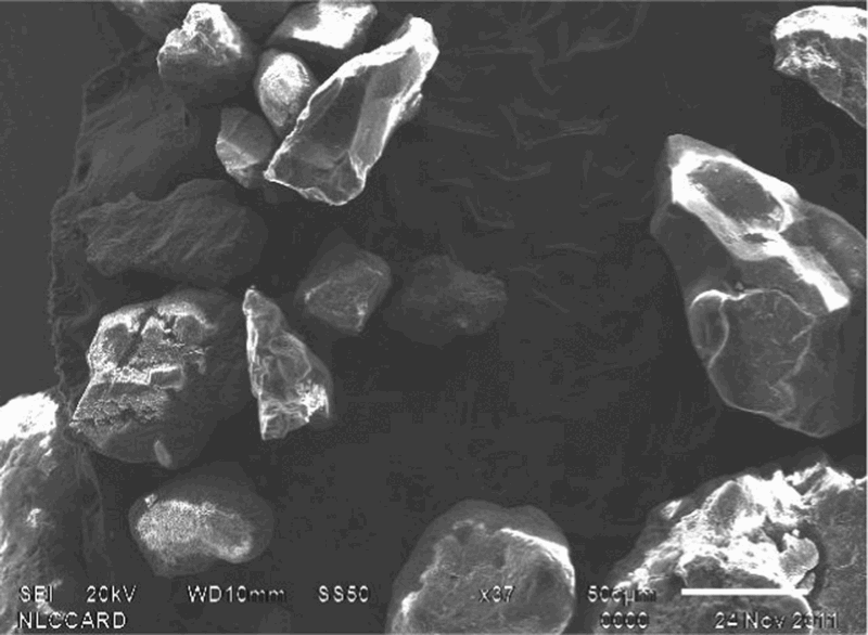
Sand profiles through SEM
Corrosion studies
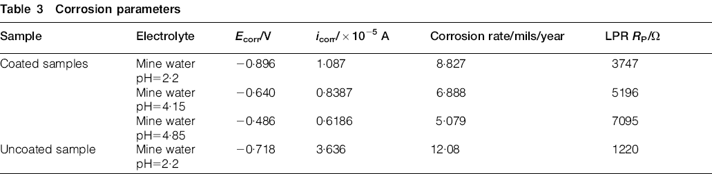
The potentiodynamic polarisation curves of the substrate material and as sprayed coating were conducted in Electrochemical Analyser CHI660D (CH Instruments, USA, 2009) in actual mine water samples at pH of 2·2, 4·15 and 4·85 are shown in Fig. 9. The corresponding electrochemical values are listed in Table 3.
Corrosion parameters
Results and discussion
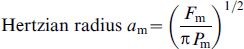
Design of safe coating thickness by dynamic Hertian impact theory
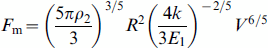
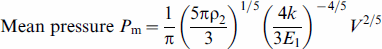
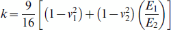
Sharp edged sand particles involved in impact process in the volute is shown in Fig. 2. They impact the surface of coating with an estimated velocity of 52·12 m s−1 and a kinetic energy of approximately 2741·5 J. The failure of coatings due to stresses arising out of the impact of these particles can be modelled with dynamic Hertzian impact theory with maximum contact ratios as shown in Fig. 3.17,24 During the impact process, the kinetic energy of the erodent particle is transferred directly to the coating and materials are removed by formation of cracks.
35
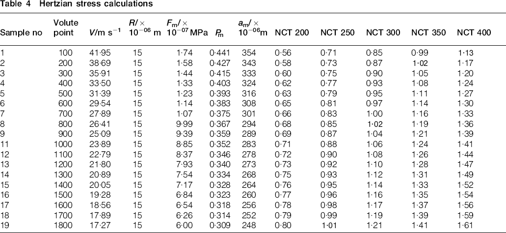
The velocity of the impacting sand particles varies at different sections of volute. The failure of coatings due to impact of these particles are estimated with dynamic Hertzian impact theory with maximum load at contact point, mean pressure, Hertzian radius, maximum tensile stress and normalised coating thickness with equations (1)–(6) as below. The performance and life of the coatings are influenced by the parameter ‘normalised coating thickness’ (NCT), which is defined as the ratio of the coating thickness CT to the Hertzian contact radius am

Hertizian stress model
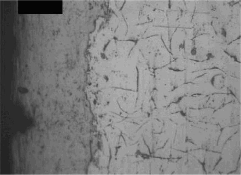
Interface profile with etching
A study on the effect of thickness of coatings proved that thicker coatings gives better protection to substrates and lower uniform strains. When NCT is >1, the coating provides better resistance against deformation and reduced the shear stress at the coating/substrate interface. When NCT<0·45, the surface microcracks dominate and when NCT>0·45, interfacial micro cracks initiate. Hence, for different places along the volute length, the velocities ‘v’ are estimated and NCT is calculated as shown in Table 4. As per the Hertzian theory of failure, the coating will fail when NCT≤1. To ensure safe strength and failure free coatings, the NCT shall be more than unity (i.e. >1) for different section lengths as per their velocities. From Table 4, it is noted that for velocities above 41·95 m s−1, in sections up to 100 mm, NCT is 1·13 for the coating thickness of 400 μm. Hence, coating thickness of 400 μm was chosen in this section. The next lower coating thickness of 350 μm was chosen between sections 101–200 mm, since NCT is 1·02 at section length of 200 mm. On the same analogy, for section of 201–800 mm, coating thickness of 300 μm was arrived at as NCT at 800 mm was 1·02. Thus to withstand impact stress of water with erodent, for varying velocities, thickness was chosen scientifically.
Hertzian stress calculations
Based on the above experiments and designs, the results obtained are discussed below.
Particle size and wear resistance
The results from literature show that the abrasive wear resistance increases with decreasingWC particle size. 36 The smaller particles have higher corrosion resistance. The smaller particles of WC have fcc structure. To have better performance of coatings, it is proposed to have multilayer system of coatings as these coatings have proved better erosion resistance. 33 Interlayers of WC–Co on other substrates have higher critical loads during scratch testing. The contact behaviour of multilayered surface systems are modelled with real surface profiles of contact stress and deformation and it was established that duplex system gives best wear resistance. 24 Hence a multi layers system with 5–8 bands with coating thickness around 50–80 μm per pass was provided and the total thickness of coating was 250–400 μm.
Characterisation of coatings
The test coupons were characterised for microstructure and other mechanical parameters as below.
Microstructure
The microstructures of the coatings and substrate were observed before and after etching through Labomed X118 Model (Lamomed, India, 2007) optical microscope. There is a good adhesion between substrate and coating as the Ra of substrate profiles range between 8–15 μm after surface preparation. This makes good bonding between the substrate and coating. The unetched sample shows carbon in free form as graphite flakes/particles which are uniformly distributed. The coatings indicate refined particles with well defined inter granular boundaries.
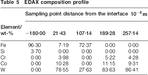
EDAX profile and inference
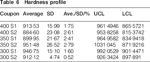
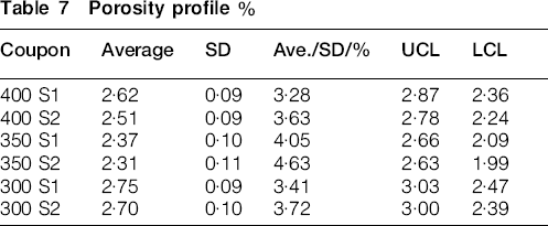
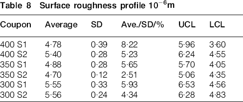
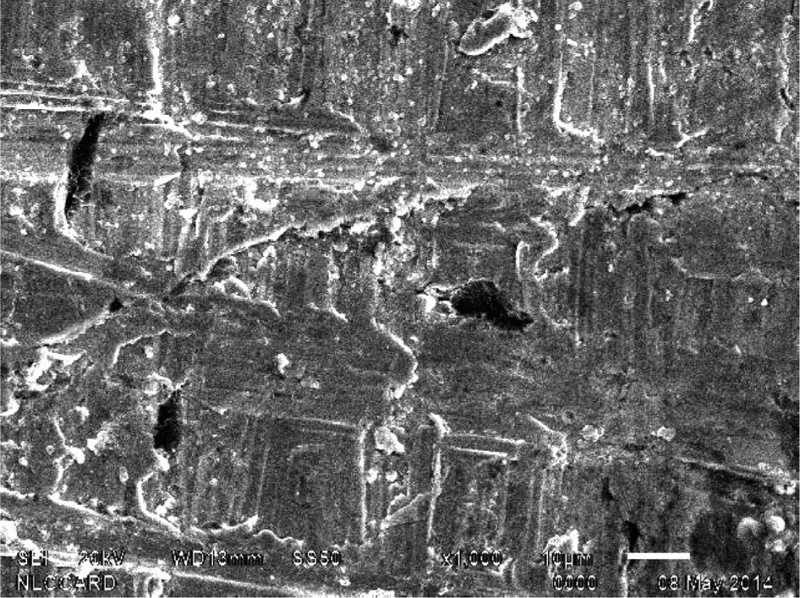
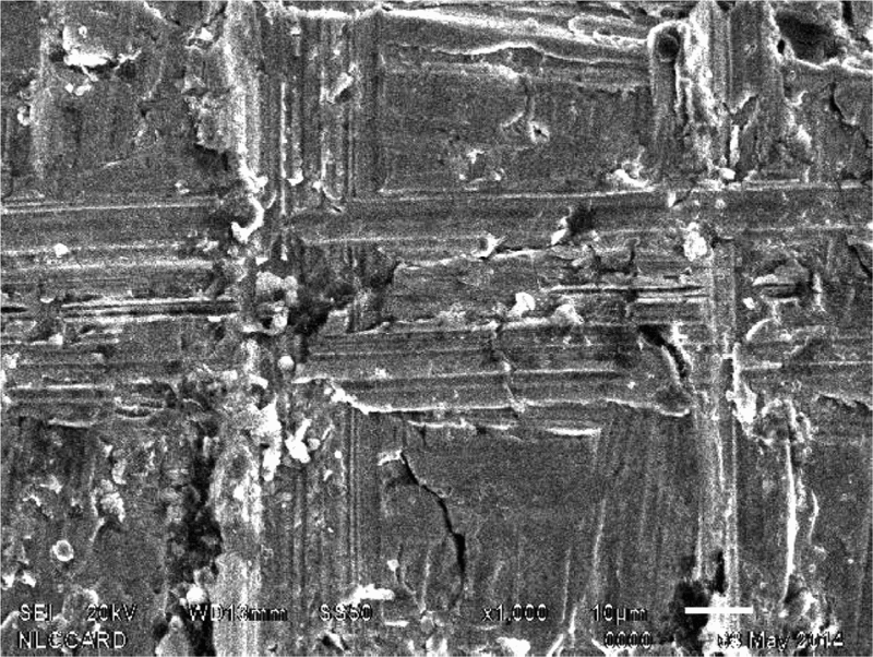
The EDAX profiles at different points of the section are analysed in scanning electron microscopy (SEM; JEOL, Model 6510 LV, Japan, 2009) and results are given in Table 5. The data in the second column represent a point at the substrate at 180 μm from the interface and have only Fe and Si components. The next column represents the concentration of elements very close to the interface and represents elements Fe, Cr and Co at fair level and W at dominant level. The fourth column also represents significant Fe and W. This may be due to the asperity pin nodes in the substrate surface at this point. While the columns 5 and 6 represent significant concentrations of Cr, Co and W indicating the dominance of coating elements. Hence, a high level of interface is seen between the coating and substrate of the casing. The interface profile is microstructurally shown in Fig. 4. It is noted that there is good interface between the substrate and coating due to considerable roughness of surface Ra = 8–15. Also the particles of substrate and coating are uniformly distributed and well defined resulting in good strength along the interface. The hardness, porosity and surface roughness of the coating measured are shown in Tables 6 Table 7 –Tables 8.
EDAX composition profile
Hardness profile
Porosity profile
Surface roughness profile
Erosion performance
The results of L9 orthogonal test are given in Table 2. The results are discussed parameter wise in the following paragraphs.
Effect of velocity on erosion rate
Velocity is considered to be the most influential factor on the erosion rate. A well established and a generalised relationship relating erosion (mass loss) to velocity is given by

Figures 5 and 6 show an obvious increase in trend on the erosion rate of grey cast iron and WC–Co–Cr coating with increasing velocity. The erosion resistance of the WC–Co–Cr coating is higher than GCI (base metal).
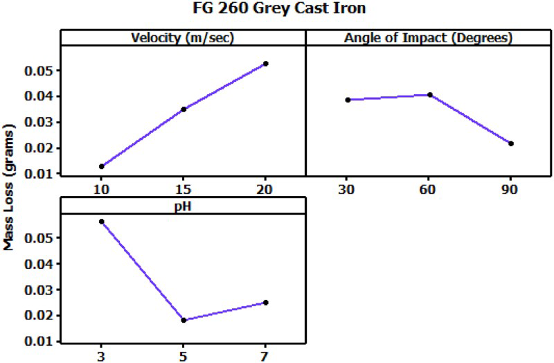
Effect of velocity, angle of impact and pH on mass loss of grey cast iron
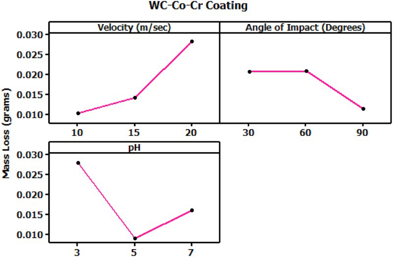
Effect of velocity, angle of impact and pH on mass loss of WC–Co–Cr coating
Effect of angle of impact on erosion rate
Erosion of the surface can be related to the angle at which the particles strike the target surface. For ductile material erosion rate is maximum at low angle of impingement and the minimum at higher angles. On contrast, erosion in the case of brittle materials is minimum at low angles and rise to reach maximum peak at a high angle of impingement. From the Figs. 7 and 8, it is noted that both the coating and the base material show ductile mode of erosion, which is mainly due to the presence of ferrite matrix present in the grey cast iron and Co–Cr matrix present in the WC–Co–Cr coating.
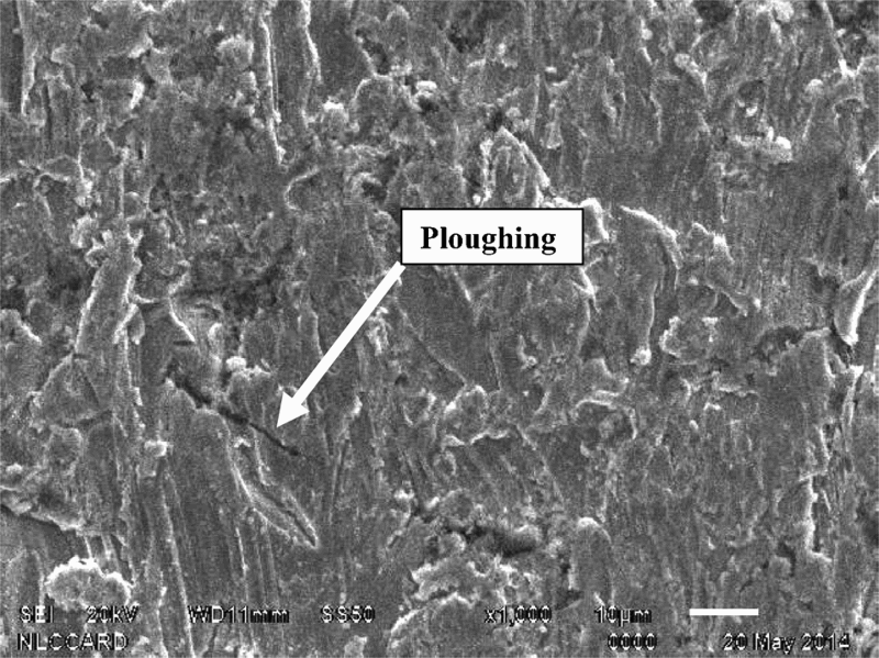
Eroded surface morphology of grey cast iron
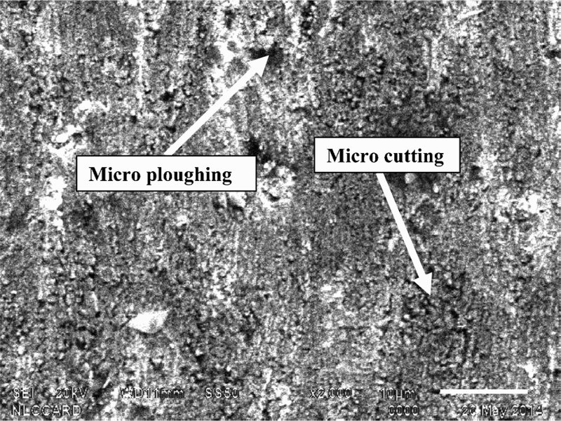
Eroded surface morphology of WC–Co–Cr coating
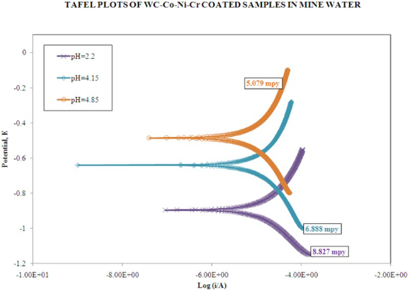
Tafel plot for mine water
Effect of pH on erosion rate
A natural trend of increase in the erosion rate with respect to the decrease in the pH level is mainly due to the presence of the more hydrogen ions present in the acidic medium.
Surface morphology characterisation by SEM
The surface examination on the grey cast iron and Co–Cr matrix present in the WC–Co–Cr coated samples was carried out and the same in presented in the Figs. 7 and 8. The grey cast iron sample indicate that the ploughing is the dominant mechanism resulting in material removal, whereas the coated sample experiences microcutting and microploughing mechanism followed by the fracture and fragmentation of mode of material removal.
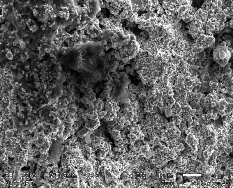
Corroded surface morphology of WC–Co–Cr–Ni coating at pH 2·22
Corroded surface morphology of WC–Co–Cr–Ni coating at pH 4·15
Corrosion results
The Tafel plots are shown in Fig. 9. They clearly reveals that erosion current densities (icorr ) of coated substrate decreased vastly compared to that of the uncoated ones in mine water pH = 2·2. The low corrosion resistance of grey cast iron appears to be related to a change in the protective nature of the diffusion barrier rust film that forms on corroding iron. In cast iron, graphite flake is cathodic to ferrite matrix. This results in rapid attack of the iron even in mild corrosive environments. The relevant curve for WC–Co–Ni–Cr coating exhibits corrosion resistance, which is indicative by the formation of a pseudo passive film on the coating surface. Figures 10, Figures 11 and 12 show the corroded surface morphologies of WC–Co–Ni–Cr coating in various pH conditions indicating spongy film with continuous network. High corrosion resistance for the impact of Cl−. 26 Electrochemical cyclic polarisation tests suggest that the coatings are not susceptible for critical pitting up to 60°C due to Cl−. 37 The electrochemical interactions between phases are the key players in the corrosion process. 38
Corroded surface morphology of WC–Co–Cr–Ni coating at pH 4·85
Conclusions
Erosion–corrosion resistant WC–Co–Ni–Cr HVOF coatings were designed optimally to withstand impact stress in different sections of volute surfaces of high capacity pumps. The erosion and corrosion performance of the coating was evaluated in simulated environments. The mechanisms of erosion in coating were established to be microcutting and microploughing.
The operating parameters such as velocity, pressure and stress distributions on the different sections of impact volute surface were assessed and accordingly the coating thickness was designed scientifically to withstand the maximum impact loads and thereby minimising the failures under mining conditions. Apart from optimisation of the thickness, the HVOF coatings applied have improved the life of the pump casings up to 12 times.
Footnotes
Acknowledgements
The authors record their sincere gratitude to the Management of M/s Neyveli Lignite Corporation (A Navaratna Enterprise, under Ministry of Coal, Government of India), for their permission to publish the research work carried out at the Neyveli Lignite Mines and extending all help during the above research work. The authors also thank profusely the administration of National Institute of Technology, Tiruchirappalli, India for facilities made available.