
Abstract
In this study, functionally graded Ni–P coatings with a gradual change of phosphorus content were deposited using a single electroless bath. For comparing tribological and mechanical properties, three types of single layer coatings were deposited. According to the results among the single layer coatings, medium P coating had the minimum wear resistance, while its hardness was not minimum. The main reason may be that the medium P coating had the minimum H/E ratio, and this ratio is a more appropriate parameter than hardness for predicting wear resistance. Results of nanoindentation test showed gradual changes in hardness profile in the cross-section of FGCs due to the gradual changes of phosphorus content in the thickness of the coatings and, consequently, gradual changes in structures. In addition, functionally graded coatings indicated much better wear resistance than single layer coatings because during the wear process cracks were effectively prevented through the thickness as a result of gradual composition and structures.
Keywords
Introduction
Martensitic stainless steel AISI 420 is widely used in plastics industry, manufacturing turbine blades and valve parts owning to its reasonable corrosion resistance, shock resistance, staining, low maintenance and relatively low cost. However, relatively low hardness and therefore poor wear resistance limit its applications, especially in some cases that require high hardness and wear resistance.1,2 In this regard, using a proper surface treatment is required to improve the mentioned weak points. Among the different surface processes, nickel–phosphorus electroless plating is widely used to improve material properties. Coatings with uniform thickness, corrosion resistance, erosion–corrosion resistance, high hardness and wear resistance are some advantages of electroless plating.3–7 The properties and microstructure of these coatings depend on their phosphorus content, so that with increasing phosphorus content the structure of coatings would be changed from crystalline to amorphous.8–11 As a result, the wear resistance of coatings would be changed by increasing the phosphorus content. In recent years, multilayer and graded coatings have received much attention for better and especially optimum mechanical and tribological properties. Researchers showed that multilayer coatings have improved performance over monolayer coatings. Furthermore, for increasing the resistance of coatings to functional failure, functionally graded coatings (FGCs) are being actively studied in coating design and developed by materials scientists.12–17 As mentioned, one of the appropriate methods for improving the surface properties of material is electroless plating. In addition, researchers have used this method for fabricating multilayer and graded coatings, but in the investigations, one or more other coating methods have been used beside the electroless plating.18–22 Although some researchers deposited multilayer and graded coatings with only electroless plating, for this purpose, they had used sequential immersion in different baths (Ni–P or Ni–P and Ni–B).23–25 In these methods, the coated samples after each step were transferred from one bath to another, which may cause poor adhesion between separate layers of coatings. Due to the mentioned problems and also due to the lack of published results in literature, in this study, FGCs were fabricated by using one electroless bath for each coating while the pH and temperature of the bath were changed at certain intervals during plating. Chemical composition, structure, wear resistance and hardness of coatings were also characterised.
Experimental
The substrates were martensitic stainless steel discs with 50 mm diameter and 6 mm thickness. The pretreatment processes have a significant role in the formation of proper coating with suitable adhesion to substrate. 26 Due to the existence of a passive surface oxide layer on stainless steel, the following processes were performed. Surface preparation of the samples was first carried out by grinding up to 800 grade SiC paper. After washing with water, electrocleaning was carried out in 1.0 N NaOH solution at 5 V for 2 min, followed by rinsing in distilled water and immersing in 30% HCl solution for 1 min. This procedure results in eliminating the surface passive film on stainless steel. After rinsing with distilled water, by using a nickel electric bath containing 240 g L− 1 NaCl2.6H2O and 250 mL L− 1 HCl in 10 A dm− 2 current for 1 min, a thin film of nickel deposited on the steel surface. According to the experiments, the absence of the mentioned deposited thin nickel film regarding the position of nickel and chromium in the galvanic table results in chromium oxidation before reduction of nickel and hence causes the lack of coating adhesion to the substrate. Finally, after rinsing samples with distilled water, they were immediately immersed in the electroless plating bath. A commercial Ni–P electroless solution (Schloter SLOTONIP70A) containing 7 g L− 1nickel sulfate and suitable amounts of additive and stabiliser was used. The electroless plating process was operated in a 1000 mL double wall beaker connected to a thermostated circulating water. The stirring of the electroless bath was carried out by a polytetrafluoroethylene (PTFE) coated magnet with 40 mm length and 5 mm diameter. To investigate the effect of phosphorus content on the structure and tribological properties of single layer coatings, coatings with different amounts of phosphorus were fabricated under different temperature and pH conditions (Table 1). In order to deposit FGCs, the temperature and pH of the bath were changed at certain intervals during the plating, as shown in Fig. 1. The mechanical properties were investigated in the section of coatings using a nanoindenter (NHTX S/N:01-03119) produced by CSM Inc. X-ray diffraction (XRD) analysis was performed using Cu Kα radiation to identify the phases in the coatings. Scanning electron microscopy (SEM, Philips-XL30) equipped with energy dispersive spectroscopy (EDS) analysis was used to study the structure and worn surface of coatings. Crystallite size of nickel crystals was calculated from the XRD pattern by Warren–Averbach and Williamson–Hall analysis. Detailed procedures of the Warren–Averbach and Williamson–Hall methods are presented in the references.27,28 The wear behavior of coatings was evaluated by using a pin on disc wear tester under a normal load of 35 N. Wear tests were performed at ambient temperature under non-lubricated conditions. The wear tests were done against an AISI 52100 steel pin with 5 mm diameter. The depth profiles of the wear tracks were detected by a Surftest SJ-210 (Mitotoyo) profilometer.
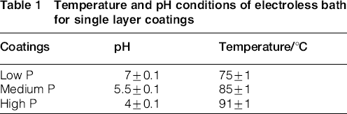
Temperature and pH conditions of electroless bath for single layer coatings
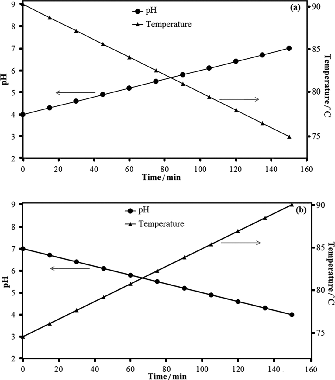
Temperature and pH conditions of electroless bath for a H–L and b L–H FGCs
Results and discussion
Structure of coatings
Figure 2 shows the surface morphology and results of EDS analysis for three single layer coatings. According to Fig. 2, three types of low phosphorous (low P), medium phosphorous (med. P) and high phosphorus (high P) coatings were fabricated successfully by using the same basic bath and with changing the temperature and pH according to Table 1. The XRD analysis for single layer coatings confirms the formation of three different coatings (Fig. 3). According to Fig. 3, the low P coating shows nickel peaks, indicating the crystalline structure of this coating. The crystallite size of this coating was estimated from the XRD pattern to be 4.9 ± 1.16 and 3.2 ± 0.11 nm respectively by Warren–Averbach and Williamson–Hall methods, which is in good agreement with the published result in the literature.29,30 A broad peak at about 45° can be observed in the XRD pattern for high P coating, which indicates an amorphous structure. Furthermore, for medium P coating, a broad peak can be observed in XRD, but its width is less than the peak width of the high P coating, so it can be concluded that the medium P coating contains a mixture of amorphous and crystalline structures. The FGCs were fabricated successfully by using one bath for each coating by changing the pH and temperature during the deposition process according to Fig. 1.
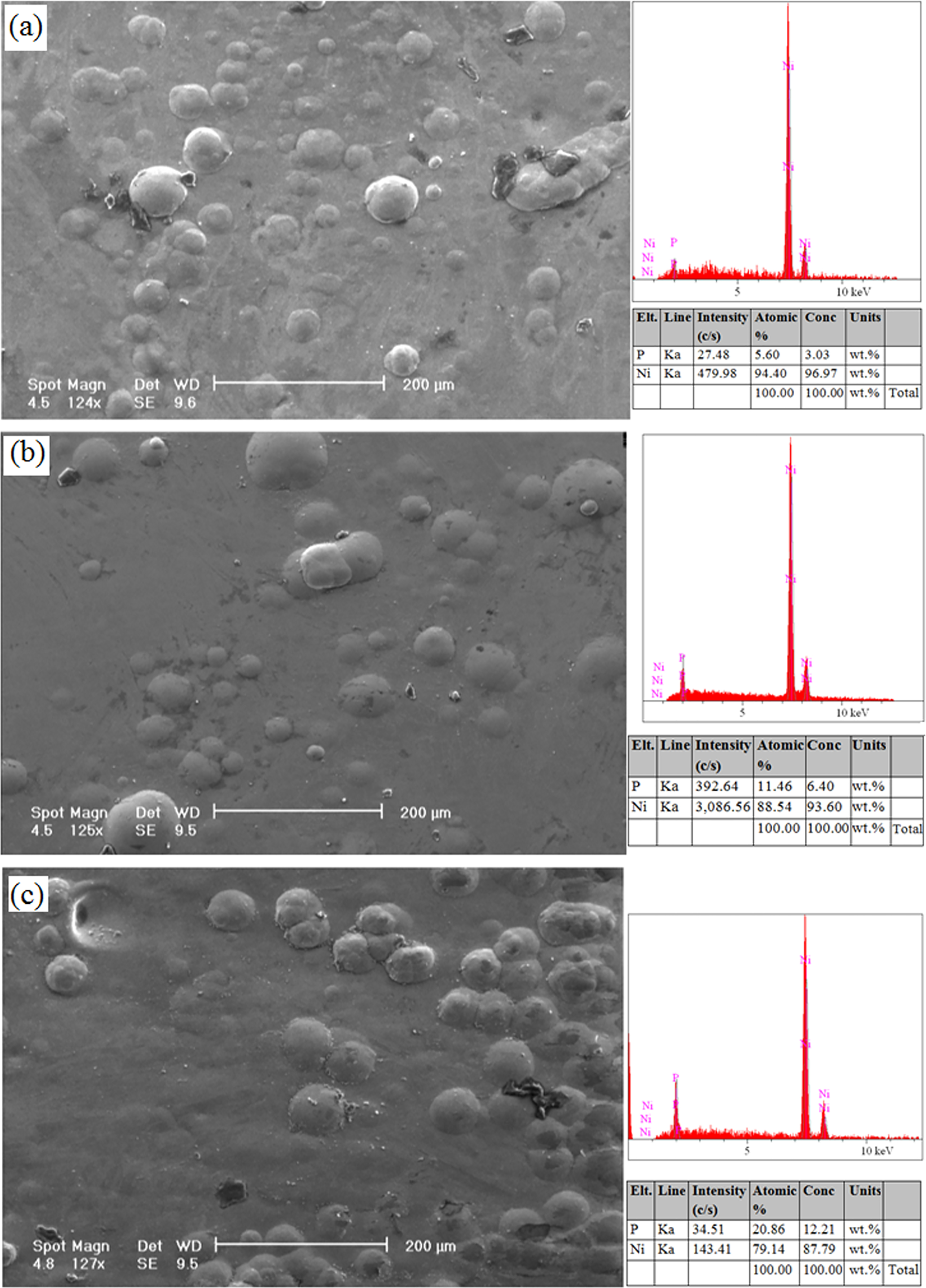
Surface morphology and results of EDS analysis for a low P coating, b medium P coating and c high P coating
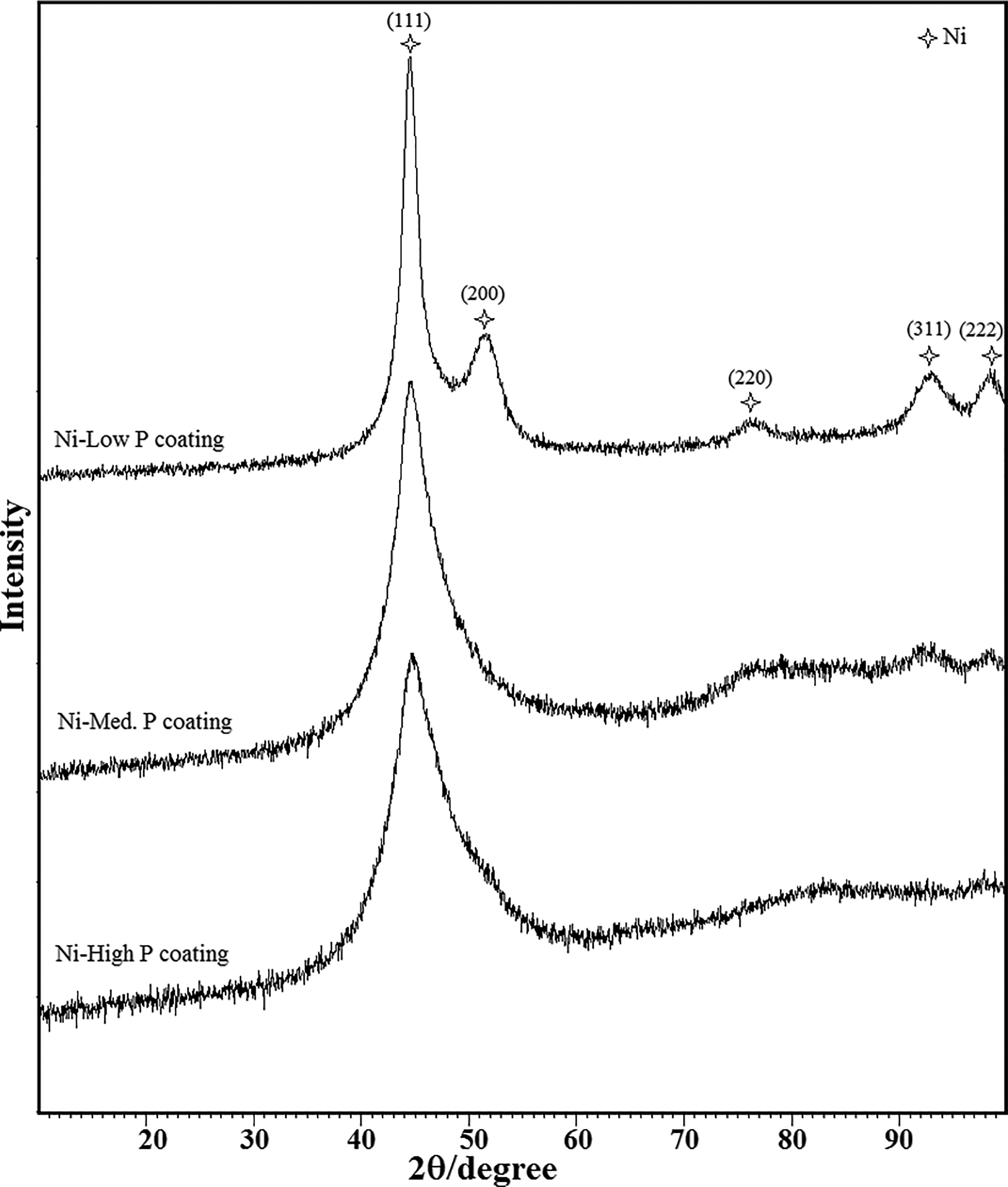
X-ray diffraction patterns for as plated low P, medium P and high P coatings
Figure 4 shows the phosphorus content through the thickness of FGCs. According to Figs. 1 and 4, with increasing pH from 4 to 7 and decreasing temperature from 91 to 75°C during plating, an FGC could be fabricated, and the gradual changes of phosphorus content in the thickness of the coating result in gradual changes in structure. In this FGC, the trend of phosphorus changes decreases from the substrate to the surface of the coating (high to low phosphorus, H–L). On the other hand, low to high phosphorus (L–H) is the other type of FGC, which is fabricated according to Fig. 1, so that its phosphorus content changes on the contrary of H–L. Figure 5 shows the cross-section of L–H, which is made of a gradual change in phosphorus content from 3 wt.-% near the substrate to 12.3 wt.-% at the top. The total thickness of each type of coatings is 50 ± 2 μm. Figure 5 shows uniform thickness and proper adhesion of the coating to the substrate.
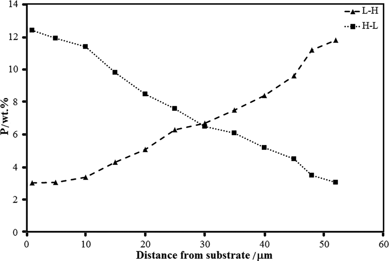
Amount of phosphorus through thickness of L–H and H–L FGCs
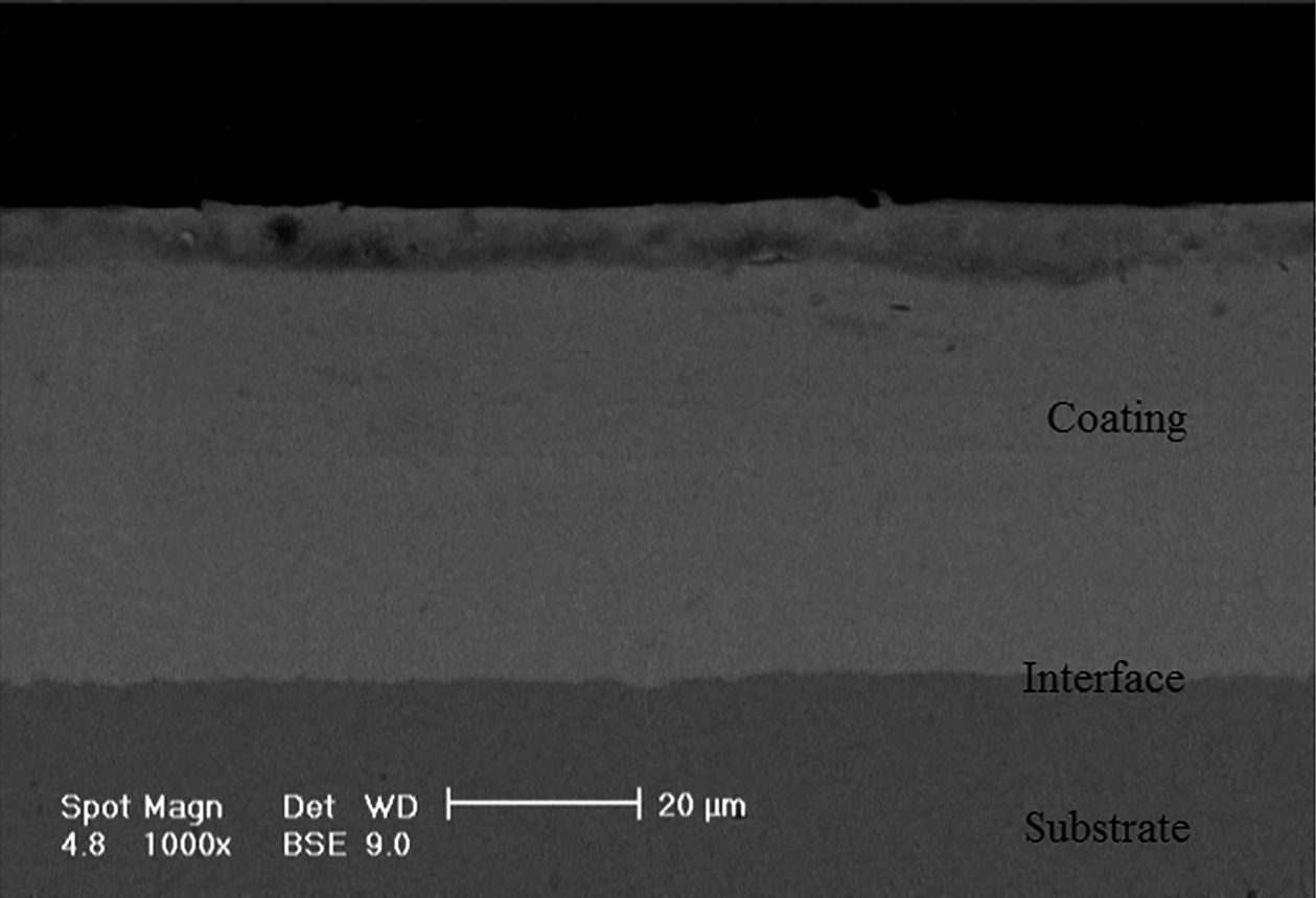
Cross-sectional micrograph of L–H functionally graded Ni–P coating
Hardness and wear resistance
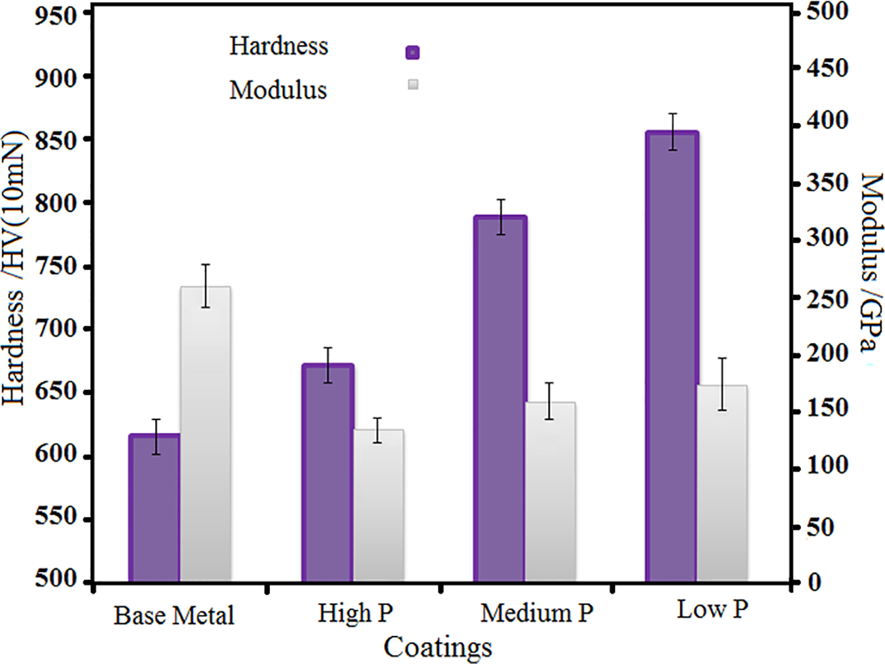
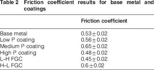
To obtain the values of hardness and elastic modulus, a nanoindentation test was performed at the cross-section of the coatings. The hardness data in Fig. 6 indicate that among the single layer coatings, high P coating has the minimum hardness, and low P coating has the maximum. According to the non-equilibrium Ni–P phase diagram (Fig. 7), the low P coating includes a single β phase that is a crystalline solution of phosphorus in nickel, and with increasing phosphorus content, the amount of β phase decreases while the amount of γ phase increases, which is generally an amorphous phase. Since the β phase has more hardness than the γ phase, the hardness of the coatings would be decreased with increasing phosphorus content. 11 Fig. 8 shows the hardness profile for FGCs. The results obtained from the nanoindentation test show a gradual hardness profile in the cross-section of H–L and L–H FGCs, which is as a result of gradual changes in phosphorus content and changes in the microstructure of coatings through the thickness. The H–L FGC has increasing hardness from the substrate to the surface of the coating, so little hardness differences between the substrate and the coating at the interface lead to prevent stress concentration near the interface, while the L–H FGC has decreasing hardness through the thickness from the substrate to the surface of the coating. The average friction coefficient and its fluctuations for base metal and different coatings are presented in Table 2. As Table 2 shows, the mean friction coefficients of coatings range from 0.45 to 0.65. According to Table 2, high P and L–H coatings with lower surface hardness have lower average friction coefficients with respect to the other coatings. Similar results have also been obtained for electroforming Ni–P alloy coatings. 31 The fluctuations in the friction coefficients are thought to be caused by the periodical accumulation and elimination of wear debris on the worn track. To study the wear behavior of coatings and the effect of phosphorus content and its gradual changes through the thickness of FGCs on wear resistance, the relationship between wear loss and sliding distance for all coatings is shown in Fig. 9, in which the high hardness of Ni–P coatings improves the triboreduction of the substrate. Figure 10 shows the depth and width of the wear track for all coatings. According to this figure, the maximum wear depth is about 38 μm. Since the thickness of the coatings is 50 ± 2 μm, it can be concluded that during the wear test none of the coatings were completely destroyed, and the steel pin did not contact the substrate. From Figs. 9 and 10, it can be concluded that the medium P coating has the minimum wear resistance, while its hardness is more than the high P coating. Although hardness is considered as a primary material property that determines the wear resistance of the material, it is not the only determining factor for wear resistance. 32 There is strong evidence that suggests the elasticity modulus can also have a main effect on wear behavior. Some authors believed that the H/E ratio is a suitable criterion for evaluating the wear properties of materials. It is also significant that the ratio between H and E, which is called plasticity index, is a main measure for determining the limit of elastic behavior in the surface contact, which is clearly valuable for the prevention of wear. Especially, the elastic strain to failure, which is dependent on the ratio of hardness (H) and elastic modulus (E), has been indicated by a number of authors to be a more appropriate parameter than the hardness for predicting wear resistance. Generally, the more the H/E ratio, the better the wear resistance.33,34 Table 3 presents H/E ratios of single layer coatings from the results of the nanoindentation test. According to the results, the H/E ratio for medium P is the lowest among the single layer coatings. Therefore, it may be concluded that its poor wear resistance between coatings is related to its H/E ratio. As Figs. 9 and 10 indicate, FGCs have more wear resistance than single layer coatings. Wang et al. suggested that for FGCs, cracks were effectively prevented due to the introduction of gradual changes in composition through the thickness of coatings, and relatively fine cracks were propagated on the wear track of the graded coating, thus inhibiting catastrophic failure under heavy load. 35 Based on the results among FGCs, H–L has better wear resistance than L–H. This is due to the fact that the hardness and H/E ratio on the top surface and near the surface of H–L FGC are more than L–H. Therefore, its surface shows higher wear resistance and prevents crack propagation and mass loss. In addition, according to Fig. 10, the depth and width of wear track for H–L FGC are minimum. Figure 11 shows SEM micrographs for the worn surfaces of the base metal and coatings. The wear track of the base metal is presented in Fig. 11a. The main wear characteristic of the base metal is deep grooves scratching parallel to sliding direction with elongated torn patches. The presence of grooves and torn patches revealed adhesive and abrasive wear mechanisms as the dominant mechanisms for base metal. These torn patches cause material displacement along the sliding path and hence resulted in deep scratches on the worn surface. Evaluation of the wear track in the high P coating (Fig. 11b) shows shallow grooves. Meanwhile, at higher magnifications, a layer structure can be observed in the wear track for the high P coating. This structure could be related to adhesion forces obtained from the temporary local fusion of worn surface and abrasive pin. In this case, a part of the material from the worn surface has been transferred to the abrasive pin, and the other part remains on the surface. Sliding repetition of abrasive pin creates new grooves and new surfaces. Furthermore, these surfaces may create temporary connections with the pin, and thus, abrasive and adhesive wear mechanisms intensify each other. During the wear process, the adhered material between worn surface and pin after plastic deformation and scratching would be torn, and finally, the layered structure would be created. Figure 11c illustrates the wear track of the medium P coating. The shallow grooves in this sample introduce an abrasive wear mechanism. Furthermore, light edges due to the fracture and detachment of material are recognisable, which indicates the adhesive mechanism as the dominant wear mechanism in the medium P coating. For low P coating and H–L FGC, the adhered material on the worn surface indicates that the adhesive mechanism is dominant (Fig. 11d and e). For L–H FGC, the presence of shallow grooves and adhered material on the worn surface reveals both adhesive and abrasive wear mechanisms (Fig. 11f).
Hardness and elasticity modulus for martensitic stainless steel and single layer coatings
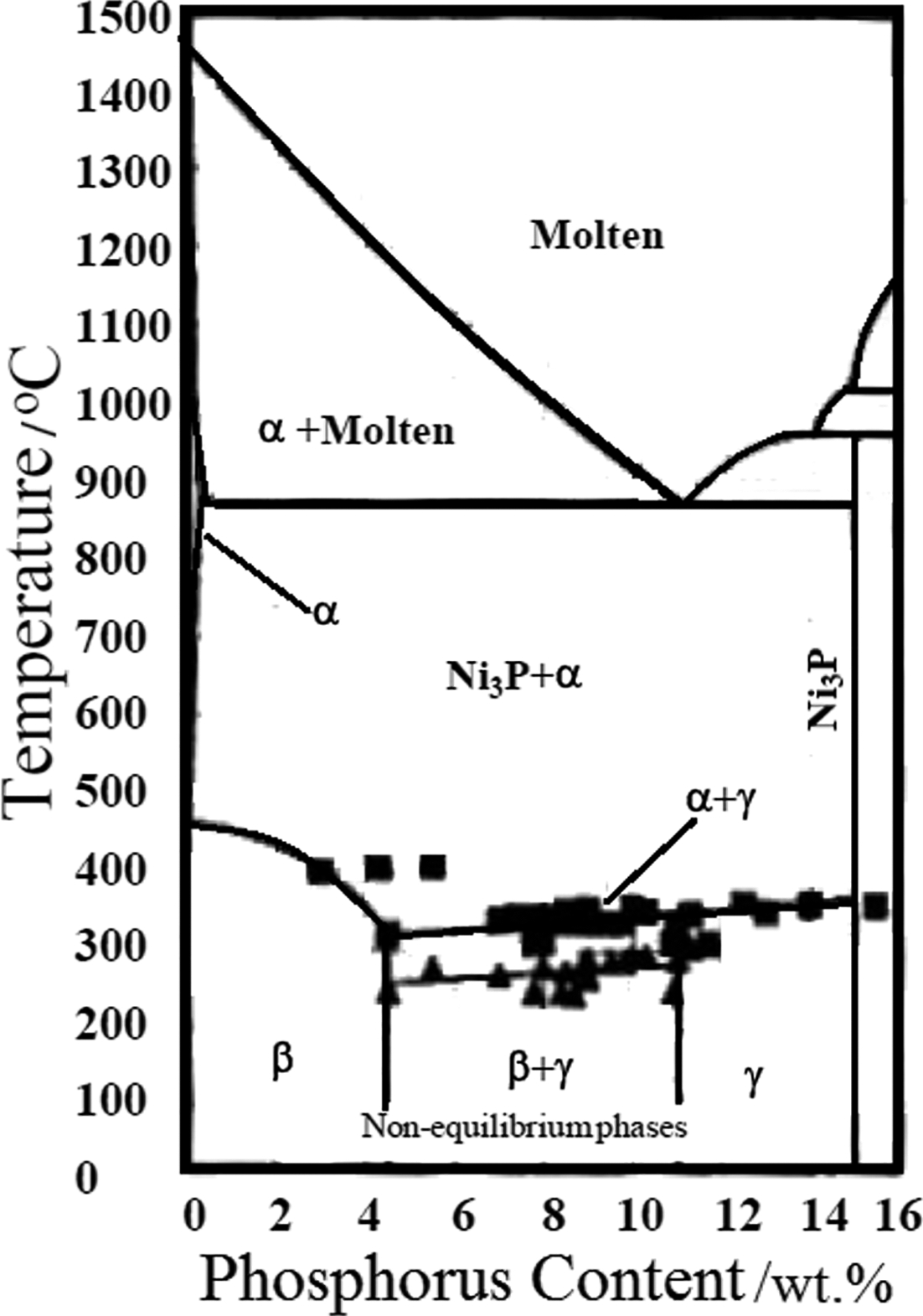
Non-equilibrium Ni–P binary phase diagram (Ref. 11)
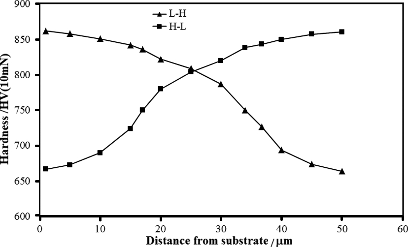
Hardness profile for L–H and H–L FGCs
Friction coefficient results for base metal and coatings
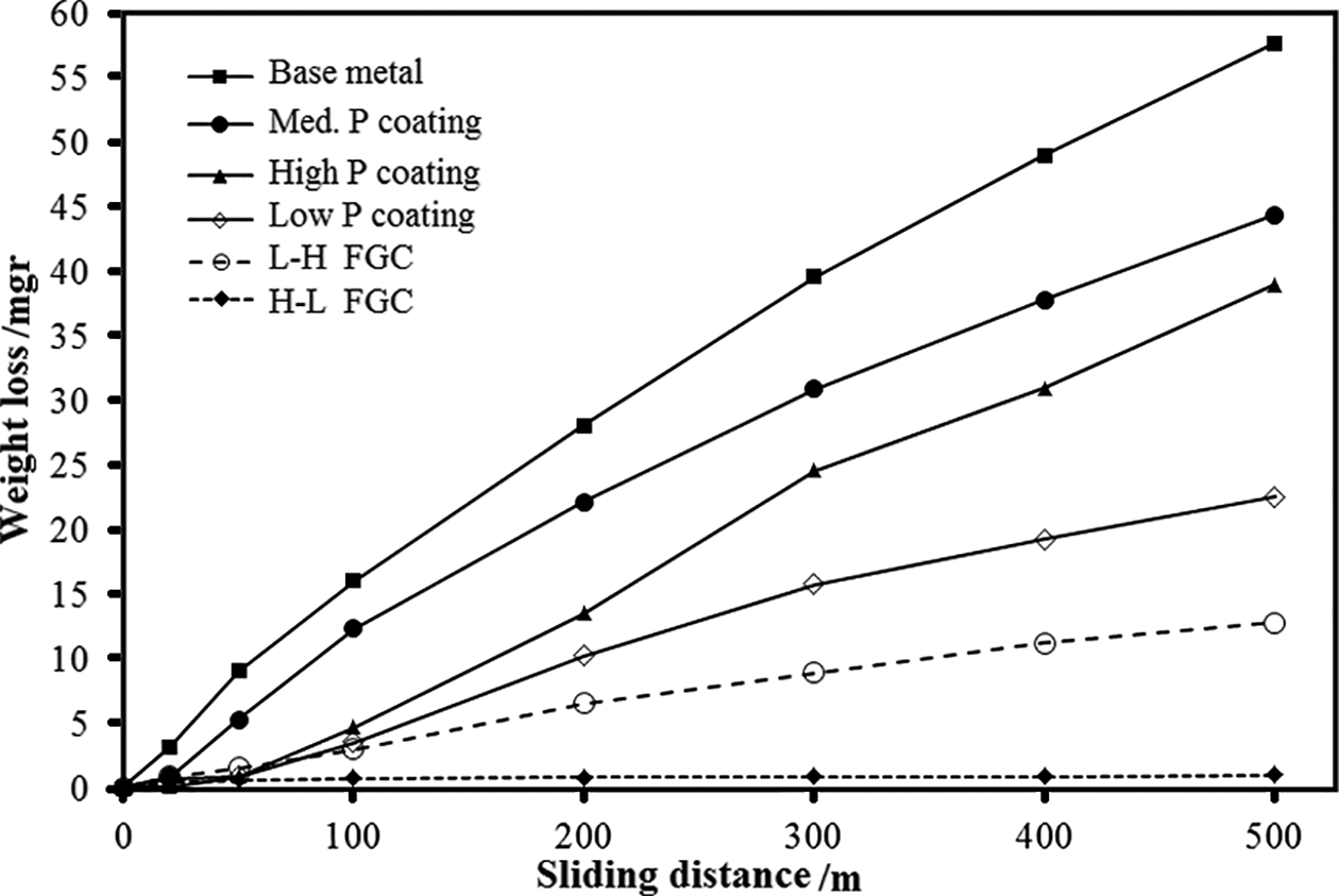
Weight loss of base metal and coatings as function of sliding distance
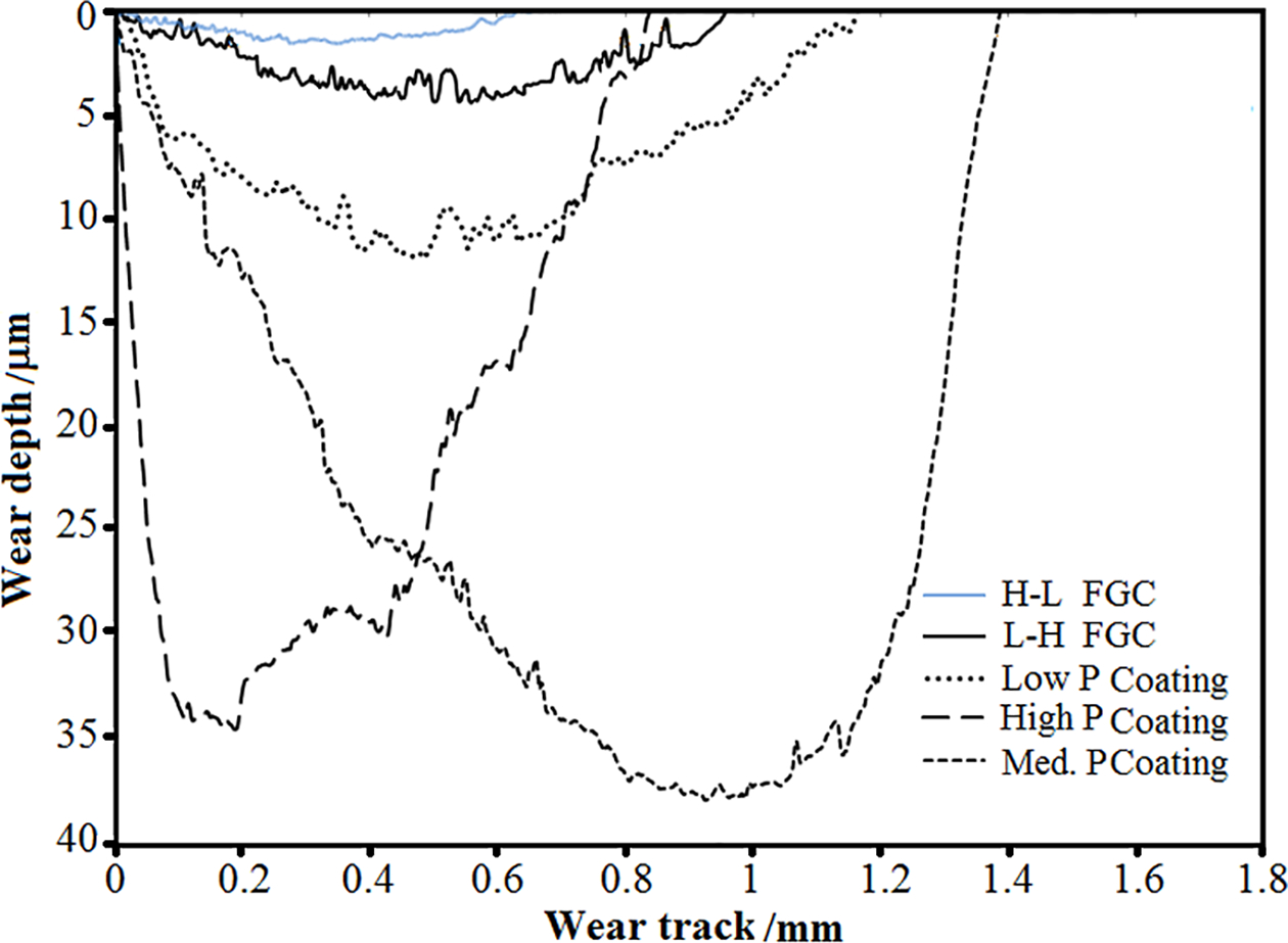
Typical track depth profiles for coatings after 500 m sliding distance
H/E ratios calculated from nanoindentation tests on single layer coatings
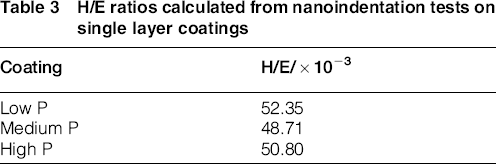
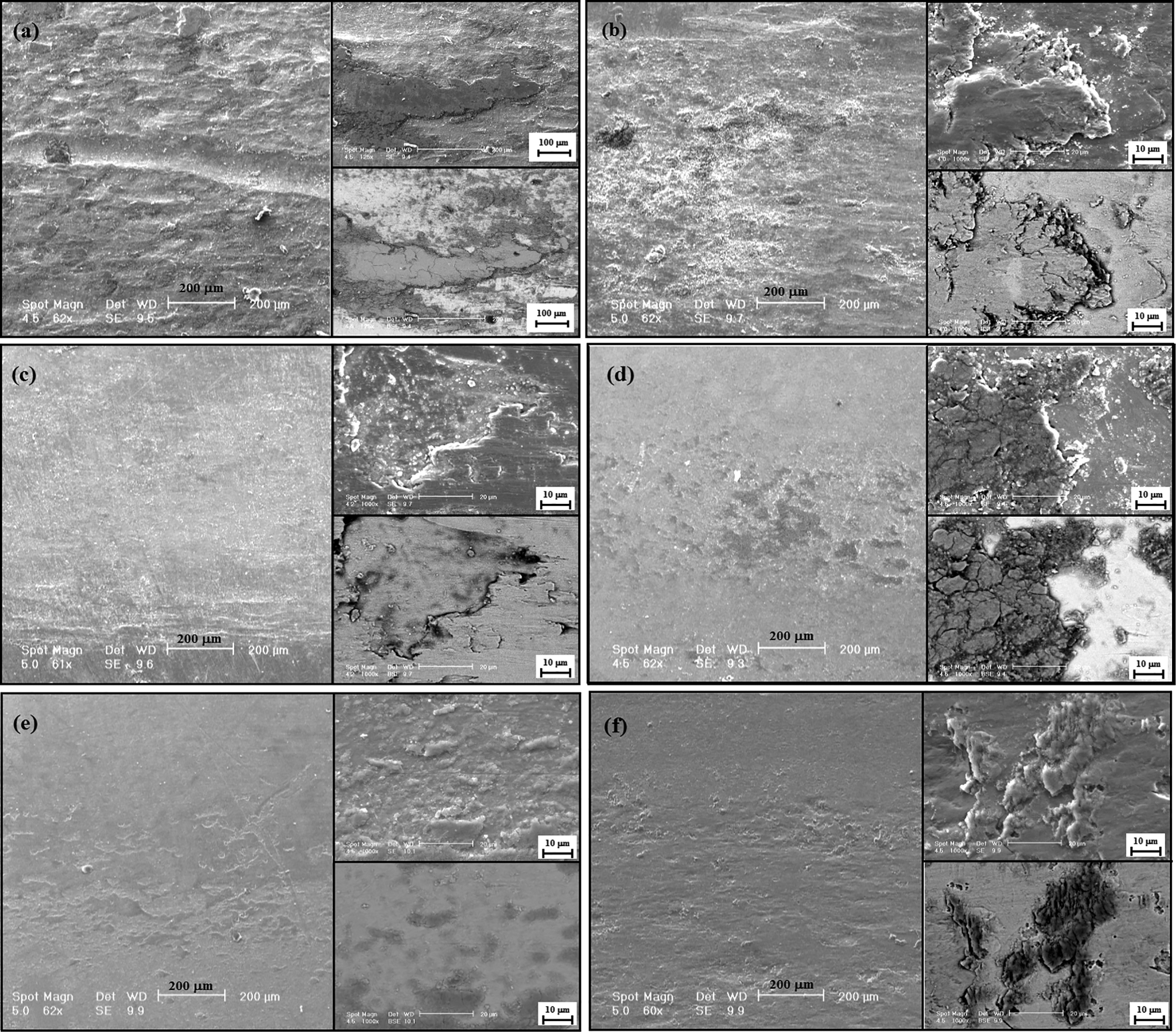
Scanning electron micrographs for worn surfaces of a base metal, b high P coating, c medium P coating, d low P coating, e H–L and f L–H FGC
Comparing the wear tracks of base metal, single layer coatings and L–H FGC reveals cracks on the worn surfaces. When the abrasive wear mechanism is dominant, these cracks appeared on the wear tracks as a result of frequent transformations of protuberances that are forced in opposition to the surfaces and move along them. On the other hand, as plated electroless coatings do not have hard particles, it can be concluded that hard protuberances are the reason of the abrasive mechanism during the wear test. On the other hand, adhesion is not the cause of wear, but only the result of contact. Wear occurs when interfaces in contact are made to slide and the locally adhered regions must separate. This separation may occur by one or two of the failure modes of solids, consequently causing a very wide range of wear rate. Results show that these two mechanisms lead to wear in samples, but their effects in different samples are not the same; for example, for low P and H–L, adhesion is the dominant mechanism, but for medium P, abrasive is dominant. As can be seen in Fig. 11, the H–L FGC exhibits comparatively smooth worn surface and has the mildest wear regime among the other coatings.
Conclusion
In this study, single layer and FGCs were successfully fabricated by electroless plating on 420 martensitic stainless steel. The structure, mechanical properties and tribological behavior of the coatings were investigated. The main results of this investigation can be summarised as follows.
Among the single layer coatings, low phosphorus coating had the maximum hardness and H/E ratio due to the presence of hard β phase and also exhibited maximum wear resistance among all single layer coatings. Medium phosphorus coating had the minimum wear resistance, while its hardness was not minimum. The main reason may be that medium phosphorus coating had the minimum H/E ratio, and this ratio is a more appropriate parameter than hardness for predicting wear resistance. Nanoindentation test results showed gradual changes in hardness profile in the cross-section of FGCs, which is a result of gradual changes of phosphorus content in the thickness of the coatings and consequently gradual changes in structures. The FGCs indicated much better wear resistance than single layer coatings because the gradual changes in their composition and structures would be prevented from crack propagation through the thickness. According to the wear tests, the weight loss for the high to low phosphorus FGC was 0.97 mg, while for the low to high phosphorus FGC weight loss was 12.8 mg. The better wear resistance in H–L FGC is due to the higher hardness and H/E ratio on the top surface of the coating.
Acknowledgement
The authors would like to thank Dr M. Abbasi for helpful assistances in this work.