
Abstract
Advanced particle diagnostic technology has been applied to establish process parameters to deposit high quality nickel based carbide cermet coatings for marine hydraulic applications. The cermet coatings are produced via the kerosene fuelled high velocity oxygen fuel (HVOF) spray process, which uses a hypersonic flame jet to melt and accelerate feedstock particles onto the component surfaces. The traditional ‘trial and error’ procedure is not technically robust, as well as being costly and time consuming. Instead, a superior method is implemented in the current study that performs real time monitoring of the process parameters associated with the HVOF flame jets. Subsequently, coatings can be produced with the knowledge of the inflight particle size, temperature and velocity profiles. The analytical results allow identification of suitable coating process parameters, which translate to coatings of lower porosity and enhanced mechanical performance.
Keywords
Introduction
The high velocity oxyfuel (HVOF) spraying is a combustion thermal spray process that uses a selection of fuel–gas mixtures including propylene, propane, hydrogen or natural gas for gas fuelled systems and kerosene for liquid fuelled systems to form a coating1,2. Coatings produced via the HVOF process are usually dense, have high bond strengths (>65 MPa), low oxide content ( < 2%) and a relatively low roughness (root mean square, ∼3 μm) for the as-sprayed finish.3–6 High velocity oxyfuel is a proven process that is used for many aircraft components that are subjected to wear environments.7,8
The focus of this contribution concerns the use of the liquid fuelled (HVOF) spray process for the replacement of an electrolytic hard chrome (EHC) plating in a corrosive wear environment. Liquid fuelled HVOF systems impart more kinetic energy to the injected particles compared to gas fuelled HVOF systems. 9 Consequently, the coatings have reduced interconnected porosity and metal binder oxidation. Kerosene fuelled HVOF systems also offer high spray rates, system robustness and lower running cost, all of which are of commercial advantage to a manufacturing applicator.
The current industrial standard as an alternative to EHC is either a HVOF WC–Co or WC–CoCr coating, but these materials do not perform well within a corrosive environment. It has been suggested10,11 that the dominant mechanism for the corrosion of WC based coatings is a combination of the corrosion of the metal binder component and degradation of the hard phase matrix. A HVOF WC–Co coating corrodes through the dissolution of the cobalt binder material and the hard WC phase. The addition of chromium to the binder can retard the dissolution of cobalt and WC by forming a protective oxide layer. 10 Therefore, proper selection of the metal binder material is essential for coating durability.
In view of the corrosion wear application, one of the key considerations is the metal binder component since dissimilar coating–substrate materials could couple to form a galvanic cell. 12 The galvanic series provides an indication of the electropotentials established when dissimilar metals are placed in contact with each other in sea water (Fig. 1). 12 The potential E (V) is measured with respect to a saturated calomel electrode (E = +0·241 V) reference cell. Accelerated attack usually occurs on the least noble material, which acts as the anode, while the more resistant noble material acts as the cathode and is protected. Common materials used in marine applications are stainless steel 316, 317 and Monel (nickel–iron–copper alloy). Selecting a metal binder as close as possible to the substrate in the galvanic series with a potential difference of < 0·25 V is recommended. 12
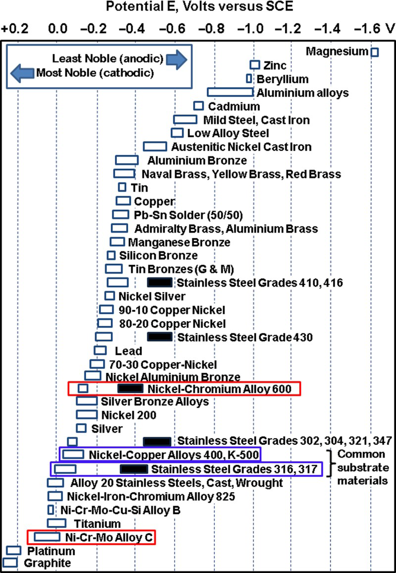
Modified galvanic series in flowing sea water as presented by Tuthill 12 : blue boxes are commonly used materials for hydraulic application; certain alloys, indicated in black bars, may become active in low velocity or poorly aerated waters and at shielded area; red boxes are potential coating metal binder materials
Dense Inconel 625 coatings deposited with liquid fuelled HVOF systems have been reported to inhibit corrosion behaviour 9 because the discontinuous micropore distribution does not allow penetration of the corrosive media.Therefore, suitable HVOF feedstocks explored in this work include nickel–chromium alloys (NiCr, Inconel) and nickel–chromium–molybdenum alloys (Hastelloy).13,14 The selective dissolution of nickel is the most severe of all alloying elements, whereas a stable oxide is formed by chromium under oxidising conditions. Molybdenum improves the resistance to pitting corrosion when chromium is present. 14 For HVOF carbide based coatings, Souza and Neville 15 have shown that WC–NiCr exhibits passive behaviour and would be compatible for use as a coating/substrate system when exposed to sea water, which is not the case for WC–CoCr. In addition, Fedrizzi et al. 16 showed that Cr3C2–NiCr coatings, in sodium chloride solution under sliding wear, presented good barrier properties, and substrate corrosion was never observed. New carbide feedstock products containing nickel based metal binder components, such as Inconel and Hastelloy, could also potentially produce coatings with superior corrosion resistance in a sea water environment.
The chemistry, manufacturing process, individual carbide size and also spray process contribute to the overall performance for tribology corrosion applications.16–19 Therefore, apart from proper feedstock selection, another objective of this work is to discuss the development of HVOF spray parameters for these carbide feedstocks. In particular, these carbide materials must retain a large volume fraction of finely distributed carbide to achieve the optimum wear properties. 20 This depends largely on minimising decarburisation of the carbide, which can occur readily at the high temperatures associated with the thermal spray process. 21
The merits of conducting process optimisation are advantageous from both technical and commercial standpoints with the main aims to (i) increase deposition efficiency (DE) and (ii) improve coating properties.22–24 Process optimisation can be implemented by measurement of the inflight particle state, 25 such as surface temperature, velocity and diameter; and relating these parameters to the coating process parameters and properties. Previous research has identified the key interactions of process parameters, such as spray distance (standoff distance), oxygen/fuel ratio and the gun technology23,24,26 in relation to DE and coating properties.
In this work, high quality nickel based carbide cermet feedstocks were selected for coating deposition using a liquid kerosene fuelled HVOF process. An advanced particle diagnostic technology was concurrently applied to establish suitable coating process parameters. Subsequently, deposited coatings were evaluated for microstructure and mechanical characteristics.
Experimental
Feedstock material and selection
Four nickel based feedstocks were chosen in this study, i.e. WC–10Ni–5Cr, WC–18 Hastelloy C type, Cr3C2–25NiCr and Cr3C2–50 Inconel 625, where the metal binder ratio is in weight percentage. The current industrial standard as an alternative to hard chromium plating is WC–10Co–4Cr, and this coating was included in this study for benchmarking purposes. These feedstocks are all commercially available as agglomerated and sintered powders with a size distribution of 15–45 μm. The trade names of the feedstocks cannot be disclosed due to commercial sensitivity.
The morphology, porosity and carbide grain size of these feedstocks were observed under a scanning electron microscope (SEM). Both WC–NiCr (see Fig. 2a) and WC–Hastelloy feedstocks exhibited a spherical morphology with fine WC grain sizes < 5 μm. Coarser Cr3C2 grains with sizes >5 μm were found in Cr3C2–25NiCr (see Fig. 2b) and Cr3C2–50 Inconel 625 feedstock, which also possessed spherical morphologies. All these feedstocks exhibited some degree of internal porosity (see Fig. 2c), which could imply that the carbides and metal phases are loosely agglomerated.
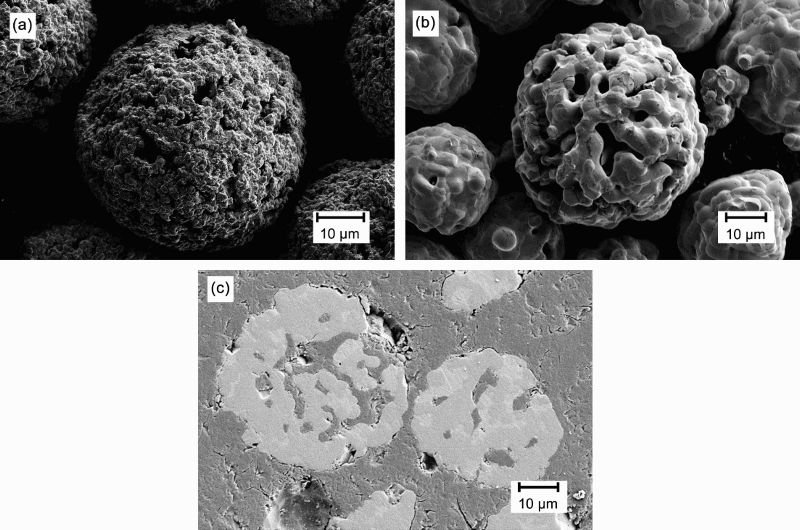
Images (SEM) of carbide based nickel feedstock
High velocity oxyfuel coating process
High velocity oxyfuel coated samples were produced using a kerosene fuelled system (GTV HVOF K2, GTV Verschleißschutz GmbH, Germany), which operates at a high pressure (∼800 kPa). In previous works, a conic expansion nozzle was found to provide optimum particle acceleration.26,27 The spray torch was machine mounted onto a robotic arm, and a consistent spray pattern was implemented. The transverse speed of the torch range was between 50 and 100 mm s− 1, and the raster path across the substrate overlapped by at least one-half of the spray footprint diameter. This allowed the measurement of DEs according to ISO Standard 17836 ‘Determination of the deposition efficiency for thermal spraying’. 28 Real time process diagnosis was implemented using the inflight particle measuring system during each HVOF spray trial.
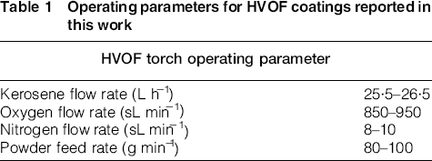
The substrates used in this work were 316L stainless steel. All substrates were degreased, preheated and grit blasted before coating procedures. The standard recommended combustion parameters used are presented in Table 1. The standoff distance for HVOF spraying was either 330 or 380 mm so that particle velocities could be maximised while allowing inflight powder melting as well as preventing overheating of the substrate.
Operating parameters for HVOF coatings reported in this work
Inflight particle measuring system
The optical sensing device (DPV2000, Tecnar Automation Ltd, Quebec, Canada) uses infrared pyrometry along with a dual slit optical device to perform inflight diagnostics on individual particles during HVOF spraying. The DPV2000 provides real time monitoring of parameters pertaining to the particle plume, which include velocity, temperature, diameter and also particle flow rate.22,25,29 Velocity is obtained by a ‘time of flight’ method, i.e. the time that a particle takes to travel between two slits on a mounted photomask is measured from two peak signals emitted by the passing particle. Concurrently, temperature measurement on the particle in flight is based on two-wavelength pyrometry theory. Temperature is directly proportional to the ratio of the two signal peaks, assuming that the heated particles are grey body emitters and that the emissivity is constant for all particles for a given spray condition.
Two types of plume measurements were performed with the DPV2000. First is the single location measurement in which the DPV2000 is programmed to execute a sweeping scan to determine the centre of a spray plume, known as the plume centre, which was henceforth used as a reference position throughout the diagnostic procedure. The second mode of the DPV2000 enables the user to perform a two-dimensional cross-sectional map of the spray plume, perpendicular to the spray direction. The detector arm was rastered across the spray plume at user specified intervals and the inflight particle properties measured at each single location. This cross-sectional map of the spray plume is useful to determine the spray plume size and the particle characteristics that pass through that location at a specific standoff distance.
Characterisation of HVOF coatings
The coatings produced underwent materialographic polishing procedures adapted from ASTM E1920 ‘Standard guide for metallographic preparation of thermal sprayed coatings’. 30 This materialographic preparation method presents a thermal spray microstructure with the least amount of damage induced to the sample.
The surface morphology and microstructure of the coatings were characterised using a field emission scanning electron microscope (Zeiss SUPRA 40VP FESEM system) in secondary electron and backscattered electron modes. Aside from using SEM to obtain images at high magnifications (i.e. greater than × 500), the bright field light microscope technique was used for low magnification observation (i.e. less than × 300) of polished thermal spray coatings. Image analysis software (ImageJ, US National Institutes of Health, Bethesda, MD, USA) was used to calculate the coating porosity levels from the captured images. A discussion on using image analysis for thermal spray coating characterisation has been covered previously. 31
An X-ray diffractometer (Bruker D8 Advance XRD system) with Cu Kα radiation at 40 kV and 30 mA was used for structural analysis to identify the phases present in the feedstock and coatings. The scan step was 0·05° with a dwell time of 5 s/step. Peaks of individual phases were identified and indexed by comparison of the diffraction pattern to a known standard from the International Centre for Diffraction Data's Powder Diffraction File.
Coating microhardness (Buehler Micromet 2103 microhardness tester) was performed on the cross-sectioned coating samples to determine the mechanical response of the coatings. Vickers indentation tests were adapted from ASTM C1327. 32
Results and discussion
Characteristics of particles passing through the plume centre
It is reasonable to assume that the HVOF plume centre will provide the most energy for heating and acceleration of the injected feedstock. The average inflight profiles of particles that passed through the plume centre, using the single location measurement method, are presented in Table 2. The average of 5000 particles is reported for each experimental run.
Summary of results for single location measurement of HVOF depositing different nickel based feedstocks*
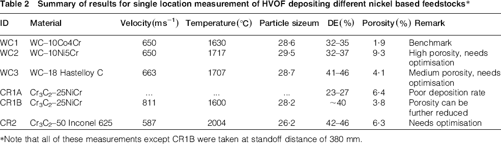
Note that all of these measurements except CR1B were taken at standoff distance of 380 mm.
The coating parameters for the WC containing materials used in runs WC2 and WC3 are based on run WC1, which was established in a previous research concerning the optimisation of WC–CoCr spray parameters. 27 It was established that the parameters used in runs WC2 and WC3 can achieve comparable particle velocities and deposition efficiencies to those of WC–10Co4Cr in run WC1. The differences in average inflight temperatures and velocity of WC1 to WC3 can be attributed to factors such as their varied metallic composition, amounts of internal porosity as well as the distribution of WC/metal matrix phases within each agglomerated and sintered powder particle.
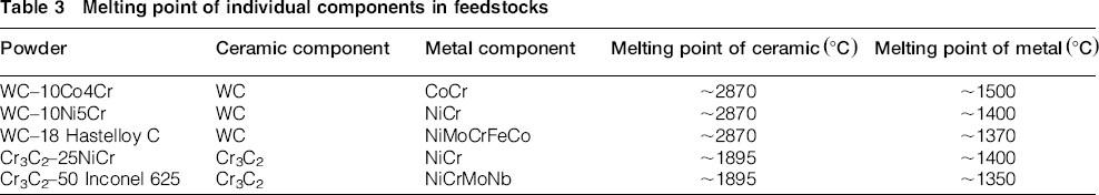
More importantly, the average temperatures of particles in runs WC2 and WC3 were below the melting point of the ceramic component; hence, only the metal binder component would be in a molten state during coating deposition, see Table 3. This is a favourable processing condition because it minimises decarburisation of the WC grains to form the detrimental W2C phase. On the other hand, the high average particle temperature for NiCr and Hastelloy C alloys, when compared to its intrinsic melting temperature (see Table 3), could promote the dissolution or oxidation of the metal binder.
Melting point of individual components in feedstocks
The HVOF kerosene flame operating parameters for runs CR1A and CR2 involving the Cr3C2 based alloy were based on manufacturer's recommendation for an equivalent kerosene fuelled HVOF system. However, a poor particle detection rate was observed in performing run CR1A; hence, no average values can be reported. Consequently, the DE attained with the manufacturer's parameters was not viable, i.e. 23–27% deposition efficiencies indicate that almost three-quarters of the feedstock were wasted. Therefore, further experiments, CR1B, were performed to optimise the HVOF coating parameters.
Table 2 also indicates the effect of altering the coating parameters; by adjusting the standoff distance to 330 mm in run CR1B, significantly higher DEs were achieved compared to run CR1A. The high detection rate of the particles permitted acquisition of 5000 particles for statistical analysis. The average particle velocity of Cr3C2–25NiCr particles in run CR1B was also significantly higher than those of the WC based feedstock; i.e., 811 ms−1 compared to 650–663 ms−1. This is attributed to the lower material density of the Cr3C2–25NiCr particles; hence, they are readily accelerated to supersonic speeds by the HVOF flame.
The operating parameters used in run CR2 resulted in the particle temperature exceeding the melting point of the ceramic component. Although the NiCr matrix inhibits the decomposition of the chromium carbide during deposition, coatings deposited at this high temperature would exhibit detrimental metal oxides. Further process optimisation was, therefore, needed to lower the average deposition temperatures, and this will be performed in future work. The intent of reporting this unacceptable result is to indicate that process optimisation is not straightforward, and several process iterations are often required.
Cross-sectional mapping of the particle laden spray plume for WC based feedstock
The single location measurements were complimented by cross-sectional mapping of the HVOF process to obtain particle distributions within the spray plume and its characteristics. The process maps of WC–10Ni5Cr are shown in Fig. 3. It is important to establish the effective spray plume size that is related to the deposition foot print of the stationary HVOF torch. Thus, the DPV2000 was programmed to perform a raster scan that was large enough to detect the boundary conditions when a sharp decline in particles arose. A reduced scan area of ∼12 mm × 12 mm with respect to the plume centre was then chosen. In comparison to conventional gas fuelled HVOF systems, this deposition footprint is large and confers a higher spray deposition rate. The particle flow maps also reveal a concentric flow pattern, which implied ideal feedstock injection parameters. Mapping was not performed for run CR2 because the single location measurements indicated that further process optimisation was necessary to lower the average deposition temperatures.
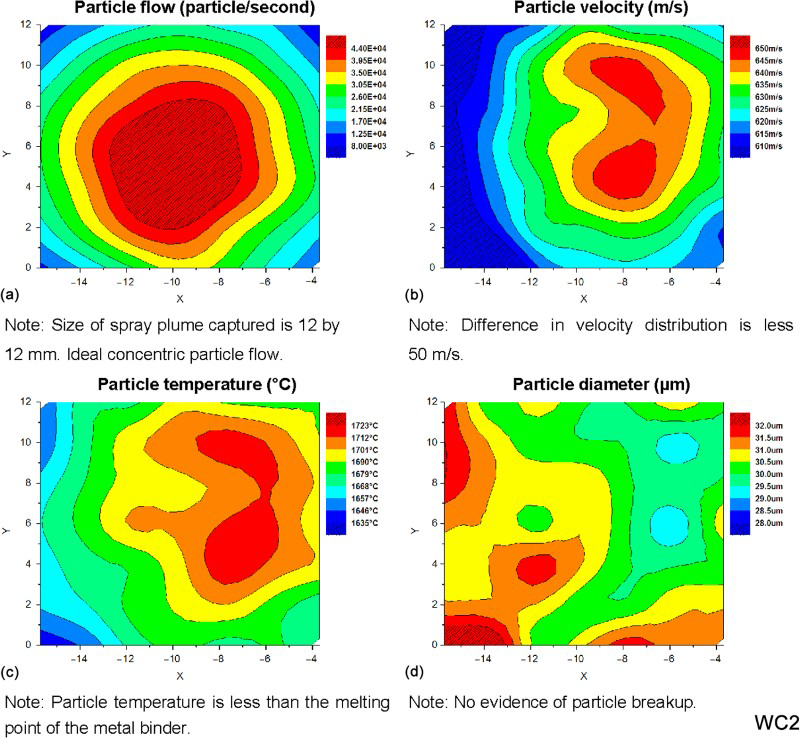
Mapping results of HVOF particle laden spray plume for WC2: WC–10Ni5Cr taken at standoff distance = 380 mm; note that X and Y axes represent cross-sectional dimensions in millimetres
From Fig. 3, the most energetic part of the deposition spray plume was present in the central region where particle velocity and temperature are the highest. The particle velocity gradient across the plume is not steep, < 50 m s− 1, and particle temperatures are less than those of the ceramic carbide (WC = 2870°C) melting point. These conditions are considered ideal for HVOF coating deposition.
The typical porosity level for the current industrial standard HVOF WC–10Co4Cr coating is ∼1·9 ± 0·4%, but those of WC–10Ni5Cr and WC–18 Hastelloy C coatings produced in this work reveal a higher porosity level (see Table 2). The notable differences in porosity levels among the three WC based HVOF coatings can be explained by their particle velocity and temperature profiles.22,29 Consider the 12 mm diameter spray plume, as approximated by the 12 mm × 12 mm scan area. The particle map profiles for HVOF WC–10Co4Cr suggest that there is a large region of uniform particle acceleration and heat transfer (see Fig. 4). Hence, coating deposition using the selected spray parameters for this particular WC–10Co4Cr feedstock resulted in low porosity. The need for individualised process optimisation is also stressed since diverse feedstocks exhibit extrinsic characteristics such as density, morphology and heat transfer properties.
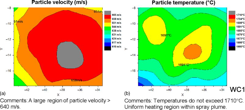
Particle velocity and temperature mapping of HVOF particle laden spray plume for WC1: WC–10Co4Cr taken at standoff distance = 380 mm
Cross-sectional mapping of particle laden spray plume for the Cr3C2–25NiCr feedstock
The particle diameter map for run CR1B shows a non-uniform particle size distribution, and the variation across the diameter of the spray plume is significant (see Fig. 5). Ideally, the particle diameter map of a HVOF spray plume should be fairly uniform (see Fig. 3d). This result suggests that the agglomerated and sintered Cr3C2–25NiCr feedstock could have broken down into its constituent parts upon injection into the energetic spray jet. In other words, although the feedstock had been sintered to agglomerate the chrome carbide and nickel chrome, the agglomerate was fragmented by the high shear forces within the HVOF jet. This conjecture is further supported by the plume results that show that the particle temperature at the outer regions of the flame exceeded the metal binder melting point and particle velocity is not ideal. Therefore, the degree of powder sintering for Cr3C2 based feedstock with large Cr3C2grains coupled with the presence of internal porosity (see Fig. 2b and c) could have led to fragmentation of the feedstock into its constituent components. To investigate if fragmentation of the feedstock can be prevented, an agglomerated and plasma densified feedstock of similar chemical composition will be explored in future studies.
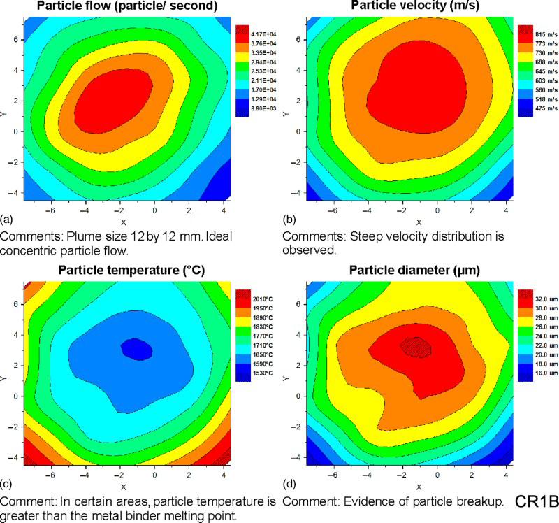
Mapping results of HVOF particle laden spray plume for run CR1B: Cr3C2–25NiCr taken at standoff distance = 330 mm
Coating microstructure characterisation: Carbide distribution and porosity level
The cross-sectional micrographs of the HVOF WC and Cr3C2 based coatings are presented in Figs. 6 and 7 and respectively. Images (SEM) revealed good physical contact at the substrate interface and a visually homogeneous distribution of carbide grains. Higher magnification images established that carbide grains were retained within the metal binder matrix.
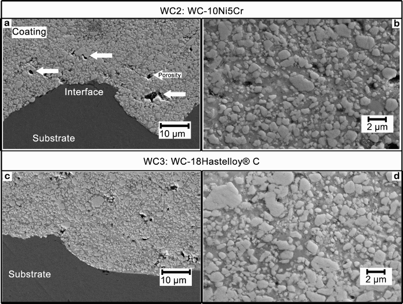
Images (SEM) of cross-sectioned HVOF WC based coatings: a, b run WC2: WC–10Ni5Cr and c, d run WC3: WC–18 Hastelloy C; WC grains are fine angular shaped particles that are light grey in colour; these WC grains are supported by surrounding metal binder, which are dark grey in colour
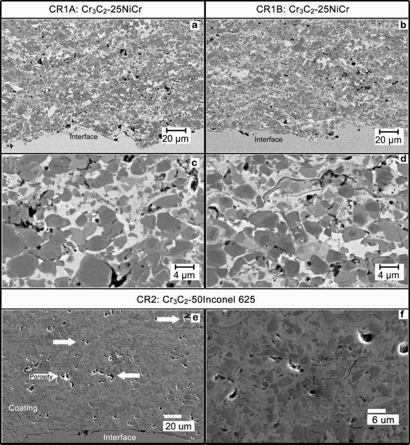
Images (SEM) of cross-sectioned HVOF Cr3C2 based coatings: a–d run CR1: Cr3C2–25NiCr and e, f run CR2: Cr3C2–50 Inconel 625; Cr3C2 grains are angular shaped particles that are dark grey in colour; these Cr3C2 grains are supported by surrounding metal binder, which are light grey in colour
Fine angular WC grains were distributed throughout the microstructure for the coatings manufactured in runs WC2 and WC3 (see Fig. 6b and d). The WC grain retention suggested that the spray parameters avoided the high temperature regimes that would cause carbide decarburisation. However, voids could still be found, highlighting a lack in coating densification. Process optimisation to increase particle velocity would potentially improve coating density. The porosity levels measured from image analysis of optical images are presented in Table 2. Note that the high porosity level of 9·3% in run WC2 could be reduced with further process optimisation.
The changes in coating parameters reduced the porosity of Cr3C2–25NiCr coatings from 6·4% in run CR1A to 3·8% in run CR1B. As seen in the microstructure from run CR1B (see Fig. 7), there are less micropores observed. Using the backscattered electron mode, the SEM image shows the NiCr metal matrix (white colour phase) binding Cr3C2 grains of different grey colour phases. These grey phases can be attributed to the multiple phases associated with inflight decarburisation and oxidation. These phases will be identified by XRD in the section on ‘Phase analysis of HVOF WC and Cr3C2 based coatings’.
The metal binder/carbide ratio is higher for coating samples from run CR2 (see Fig. 7). The Cr3C2 grains were difficult to detect, which could indicate some carbide decarburisation and dissolution with the metal phase during deposition. The coating porosity of 6·3% could also be reduced with further optimisation.
Phase analysis of HVOF WC and Cr3C2 based coatings
The XRD patterns of the WC based feedstock and coatings have been normalised and indexed against the database (see Figs. 8 and 9). The plots reveal not only crystalline phases of strong WC peaks but also the weak presence of W2C. The relative amount of W2C formed in both HVOF WC based coatings is not significant since the scanned W2C diffraction peaks have much lower intensity compared to WC peaks. In the case of WC2, only one W2C peak could be indexed. Therefore, this implies that the coatings retained amajority of the starting mono-WC grains from the feedstock. It also highlights the capabilities of the advanced kerosene fuelled HVOF system, as well as the metallurgical stability of these WC based feedstocks, to deposit coatings without the excessive formation of brittle W2C or other complex phases such as (W,Cr)2C 33 that would be detrimental to the coating mechanical performance.
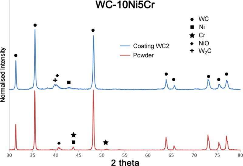
X-ray diffraction results of run WC2: WC–10Ni5Cr (Top spectra is for the coating and the bottom spectra of the powder.)
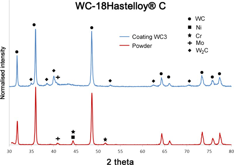
X-ray diffraction results of run WC3: WC–18 Hastelloy C (Top spectra is for the coating and the bottom spectra of the powder.)
There is also evidence of a peak difference for the metal binder of NiCr and Hastelloy C, which suggested that oxidation and phase changes occurred. Less phase transformation processes are expected with increasing particle velocities and decreasing flame temperature of the HVOF coating process. This concurs with the notion that further process optimisation of HVOF parameters should be conducted for these feedstocks.
In contrast to the HVOF WC based coatings, multiple phase transformations occurred for Cr3C2 based coatings as depicted in Figs. 10 and 11. This is due to the excessively high temperature processing during coating formation so that phases such as Cr3Ni2 and Cr2O3 were found in the as-sprayed coatings. As previously mentioned in Table 3, Cr3C2 grains exhibit a lower melting point compared to WC grains. Therefore, to reduce the extent of decomposition, proper optimisation of the HVOF flame jet is recommended. For run CR1B, i.e. the Cr3C2–25NiCr HVOF coatings, the high degree of decarburisation and oxidation of the metal binder phase is further evidence that the feedstock is broken down into its constituent parts as it is injected into the energetic spray jet. This resulted in excess heat transfer to particle fragments, which melt and decompose to form metal oxides. Nonetheless, NiCr and Cr3C2 are still present within the coatings of run CR1Aand CR1B.
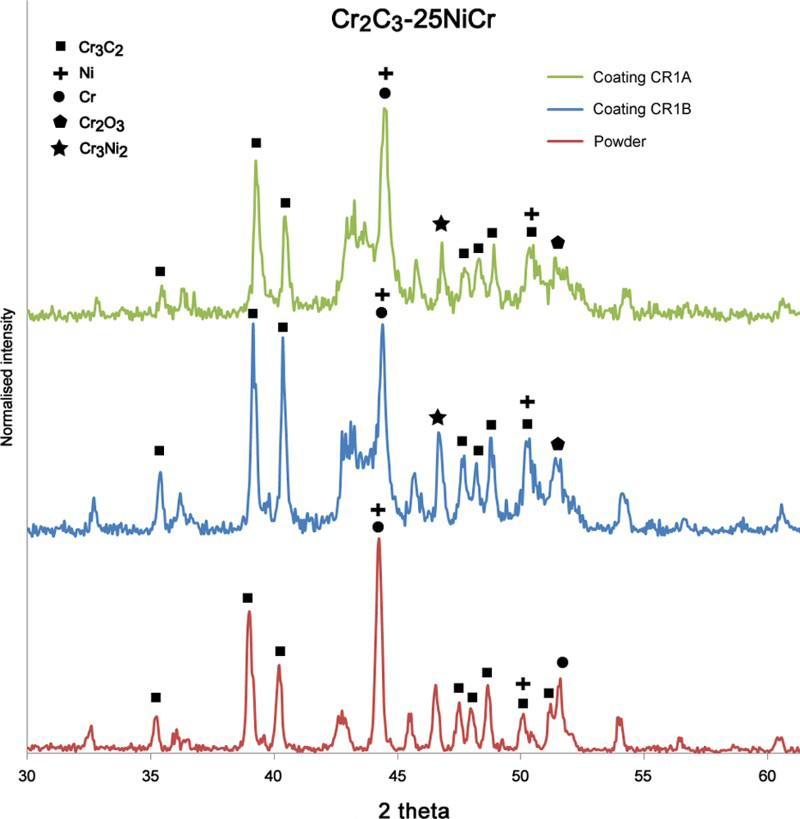
X-ray diffraction results of run CR1: Cr3C2–25NiCr (Top two spectra is represent coating and the bottom spectra of the powder.)
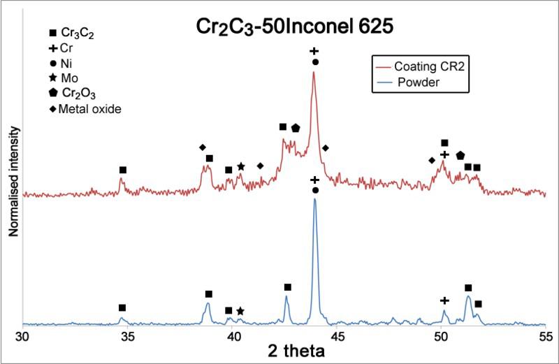
X-ray diffraction results of run CR2: Cr3C2–50 Inconel 625 (Top spectra is for the coating and the bottom spectra of the powder.)
For run CR2: Cr3C2–50 Inconel 625 coatings, there is also decarburisation of the Cr3C2 since additional peaks can be detected in the XRD spectra. The high temperature of the HVOF flame has also caused the oxidation of the Inconel 625 binder material to form numerous metal oxide phases.
Mechanical properties via microhardness
The microhardness indentation test quantitatively measures a material's resistance to deformation under an applied load. This test is widely used for thermal spray coatings and can provide an indication of coating performance under a stress field. The microhardness test results for the coatings produced in this work are presented in Table 4. The standard deviation and coefficient of variance of the measured results are also presented.
Compilation of Vickers microhardness test results of HVOF coatings
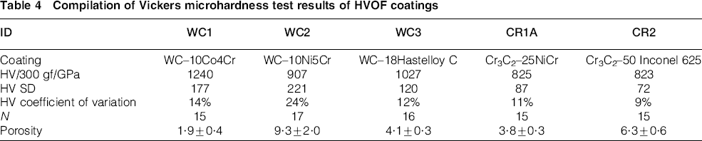
The hardness values achieved are comparable to the benchmark values of run WC1 HVOF WC–10Co4Cr, i.e. HV300 gf = 1240 ± 177 (N = 15). The porosity level is also presented. With further process optimisation using the inflight particle diagnostic tool, a more dense coating microstructure would be expected for WC–10Ni5Cr or Cr3C2–50 Inconel 625 and hence an associated increase in microhardness.
Conclusion
Advanced inflight particle diagnostics have been employed to ascertain the spray processing parameters for a new range of HVOF carbide coatings that contain nickel–chrome, Inconel and Hastelloy metal binder. Four types of carbide coatings were explored and benchmarked against the current industrial standard of WC–10Co4Cr coatings using a kerosene fuelled HVOF system.
The spray parameters for the WC based materials allowed the average temperatures of particles to be below the melting point of the ceramic component: hence, only the metal binder was in a molten state during coating deposition. However, the mapping profile of these WC based materials showed that there is only a small region of uniform particle acceleration and heat transfer. Thus, these coatings exhibited higher coating porosity compared to HVOF WC–10Co4Cr coatings. Therefore, individualised process optimisation is necessary for different feedstocks due to extrinsic feedstock characteristics such as density, morphology and heat transfer properties.
Process optimisation for Cr3C2–25NiCr coatings was performed, and higher deposition efficiencies were achieved. However, it was found that the agglomerated and sintered Cr3C2–25NiCr feedstock could have fragmented into its constituent parts on injection into the energetic spray jet. This resulted in a high degree of decarburisation and oxidation of the metal binder. The feedstock break-up can be prevented using an agglomerated and plasma densified material of similar chemistry.
It was found that the operating parameters for Cr3C2–50 Inconel 625 resulted in a particle temperature that exceeded the melting point of the ceramic component. This condition led to extensive decomposition of the chromium carbide during deposition, and these coatings tended to exhibit oxide phases. Further process optimisation is, therefore, needed to lower the average deposition temperatures and will be performed in future work.
The prime intent of this current work has been to demonstrate the implementation of advanced diagnostic methods within an industrial environment to achieve processing windows for unique cermets. The process optimisation has enabled benefits with regard to achieving functional microstructures that have been manufactured under high DE conditions.
Footnotes
Acknowledgements
The authors thank messieurs M. Valimberti and P. Hawkey from United Surface Technologies, P. Richings and C. Boschen from MacTaggart Scott Australia and A. Moore from Swinburne for expert assistance in the preparation and procurement of samples used in this work. The authors acknowledge the support of the Defence Materials Technology Centre, which was established and is supported by the Australian Government's Defence Future Capability Technology Centre (DFCTC) initiative. This work was performed in part at the Biointerface Engineering Hub in the Victorian Node of the Australian National Fabrication Facility (ANFF).