
Abstract
AZ31 alloy is used as a lightweight material for structural application in the automobile and aircraft production. However, alloy AZ31 is known to have poor corrosion resistant due to high electrochemical activity. In this study, the possibility of improving the corrosion resistance by applying protective coatings deposited by the low pressure cold spray process was investigated. The relative performance of each cold sprayed corrosion preventive coatings was assessed in accordance with American Society for Testing and Materials standards. The data for the bare AZ31 alloy were initially obtained and used as a reference point to compare the corrosion protective performance of different preventive coatings. Electrochemical behaviour of each coating composition was analyzed after a given time period of the accelerated corrosion test. Microstructure and mechanical properties of the deposited preventive coatings are also discussed. The cold sprayed preventive coatings provide sufficient protection to substantially reduce the corrosion rate of alloy AZ31.
Introduction
Weight reduction is the most cost effective means to reduce fuel consumption and greenhouse gases from the transportation sector. It has been estimated that for every 10% of weight eliminated from a vehicle's total weight, fuel economy improves by 7%. 1
The best way to achieve weight reduction without compromising rigidity is to replace steel with lighter materials. Magnesium–aluminium–zinc alloys and, in particular, AZ31 with its high strength/weight ratio are considered to be one of the most promising lightweight materials for structural and substructural components in vehicle production. 2 However, joining by conventional fusion welding of components made of AZ31 alloy with parts made of other materials, most frequently steel or aluminium, presents a problem because the weldability of AZ31 components by conventional fusion welding is poor. 3 Alternative joining technologies are clinching 4 and fasting. 5 While the usage of clinching is limited due to low dynamic strength of clinched magnesium alloy parts, 6 using steel or aluminium bolts is one of the most commonly used processes for joining magnesium–aluminium–zinc alloy components.7,8 However, due to oscillatory motion during cyclic loading, the friction between the bolt tightened components makes the joint susceptible to fretting fatigue, especially when high tightening torques are employed. The fretting fatigue can cause crack initiation around the bolthole, thus affecting the durability of the bolted joint. 9 The probability of crack initiation can be decreased efficiently if the coefficient of friction between the bolted components is considerably reduced. 10 For this purpose, a number of coatings have been used, mainly based on the incorporation of dry lubricants, such as graphite or molybdenum disulphide, in a polymer matrix. 11 However, cyclic loading usually leads to the abrasive wear of such soft coatings, reduction of the coating thickness and the increase in the coefficient of friction. 12
Fretting damage is a combination of abrasive and corrosive wear. 13 Corrosion is another important problem of bolted joints combining magnesium–aluminium–zinc alloy components with steel or aluminium parts. Owing to the big difference in the electrode potential, magnesium–aluminium–zinc alloy components are anodic to structural metal components and, therefore, subjected to severe galvanic corrosive attack known as contact corrosion.14,15
One of the most effective ways to minimise galvanic corrosion of magnesium–aluminium–zinc alloys is to apply protective coatings. 16 However, to provide adequate corrosion protections, there are numbers of challenging requirements to the protective coating, such as the coating must be uniform, well adhered, and pore and crack free. The majority of the existing electrochemical surface treatment techniques do not provide sufficient protection for magnesium–aluminium–zinc alloy components due to uneven surface potential across the magnesium alloy parts, resulting in uneven and unpredictable coating thickness.17,18 Thermal spray coating technologies also have several shortcomings when used for corrosion protection of magnesium–aluminium–zinc alloy, including high porosity and crack formation in the coating layer as well as adverse residual stresses due to substantial differences in coefficients of thermal expansion between the coating and substrate. 19
Therefore, there is a need in both anti-fretting wear and corrosion resistant coatings that are able to maintain a relatively low friction coefficient on AZ31 alloy components and a deposition technique for forming the coatings. In the last few years, a lot of attention attracts a rapidly emerging industrial coating technology—cold spray (CS), a spraying process in which the feedstock materials are accelerated in a supersonic gas jet and kinetically deposited on the substrate at relatively low temperatures and, therefore, remaining in the solid state. 20 Consequently, there are no thermal effects such as oxidation, residual stresses and/or undesirable metallurgical transformations that usually occur during the particle melting process, and the formed coatings are dense with extremely low porosity. 21
It has been demonstrated that the low pressure cold spray (LPCS), a low pressure version of the CS process, can be effectively used for corrosion protection of aluminium and magnesium based alloys. 22 It has also been shown that cold spray coatings can be used for fretting wear reduction of aluminium against steel. 23
The objective of this work was to study whether the LPCS formed coatings can be engineered to provide both wear and corrosion resistance for magnesium–aluminium–zinc alloy components and, in particular, AZ31 parts.
Experimental
Cold spray materials
Atomised, commercially pure Al powder with an average particle size of 45 μm, Zn metal powder with an average particle size of 30 μm, spherical Ni powder with an average particle size of 45 μm and fused Al2O3 with an average particle size of 25 μm were used for coating deposition. Powder blends were obtained by mechanically mixing the powder composition (PC) components for 10 h. The prepared PCs are listed in Table 1.
Specimen component contents (Zn/Ni ratio is constant)
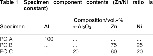
Corrosion protection coatings were deposited on 1·8 mm thick AZ31 magnesium alloy substrates (chemical composition in wt-%: Al 3·1; Zn 0·73; Mn 0·25; Si 0·02; Cu < 0·001; Fe < 0·005; Ni < 0·001; Ca < 0·01; Zr < 0·001 and Mg balance).
LPCS parameters
Cold spray system Centerline SST was used for coating deposition. For all the deposition experiments, the LPCS gun inlet air temperature and pressure were fixed at 500°C and 0·62 MPa respectively. The LPCS spray gun was held by a three-axis robot at a constant standoff distance of 15 mm and moved across the substrate surface at a transverse speed of 2 mm s− 1. The powder feeding rate was ∼20–30 g min− 1. Before the deposition process, the substrates were grit blasted using alumina powders with an average particle size ∼180 μm. The supersonic nozzle of the LPCS gun had a custom made nozzle extension, which was equipped with a cooling system, allowing to considerably reducing clogging during the spraying process.
Corrosion characterisation
Corrosion behaviour of the formed corrosion resistant coatings was studied by conducting the accelerated salt spray tests according to American Society for Testing and Materials (ASTM) B117. Samples were subjected to salt fog environment for 25, 50 and 194 h respectively using the ATLAS CXX advanced cyclic corrosion exposure system. Open circuit potential (OCP) and DC polarisation measurements were performed using the Biologic SP-150 potentiostat/galvanostat equipped with EC-lab software. The experiments were carried out in a conventional three-electrode cell, consisting of a working electrode test sample with 4·74 cm2 of exposed area, a graphite counter electrode and a saturated calomel reference electrode (SCE) with a potential of 0·244 V with respect to the standard hydrogen electrode at 25°C. The solution concentration inside the reference electrode compartment was 3·0M KCl. Electrochemical potentials were measured at room temperature in nitrogen aerated 3·5 wt-% NaCl solution (pH 7) with reference to the SCE. The potentiodynamic polarisation curves were retrieved at a scan rate dE/dt of 0·3 mV s− 1 from − 100 to +200 mV with respect to the OCP with the purpose of minimising the time dependent probability of developing crevices during the test. The Tafel extrapolation of the anodic and cathodic slopes was performed using Tafel fit, where the corrosion current (Icorr) was yielded upon the extrapolation matching the corrosion potential (Ecorr). OCP measurements were performed by immersion of the coated samples in the 3·5 wt-% NaCl solution at 23°C with the potential sweep recorded each 0·5 s over a period of 20 min. Corrosion rate (CR) was calculated in accordance with ASTM G102 Standard Practice.
Microstructure and property characterisation
Microstructure characterisation of the formed coatings was performed according to ASTM E1588 using the FEI Quanta 200F SEM with EDAX attachment. The adhesion strength of the coatings was evaluated in accordance with ASTM C633 by employing the automated Zwick/Roell materials testing machine Z150. The microhardness of the coatings was measured according to ASTM E384 using the Dynamic Ultra Micro Hardness Tester DUH-W201S with maximum loading force of ∼1961 mN. Elasticity modulus was calculated based on a load/unload curve obtained during microhardness test.
Friction and wear characterisation
The coating wear process was studied in a controlled manner using ball on disc tribometer in accordance with ASTM G99. An 8 mm diameter steel ball with normal load of 5 N and sliding velocity of 60 rev min− 1 was used.
Results and discussion
OCP measurement
To evaluate the corrosion performance and estimate the tendency of the formed coatings to electrochemical oxidation, the coated samples were suspended in the 3·5 wt-% NaCl solution (pH 7) for 20 min at room temperature. The evolution of OCP for AZ31 as a reference material and AZ31 coated with three different coating compositions (PC A, PC B and PC C) are shown in Fig. 1a and b.
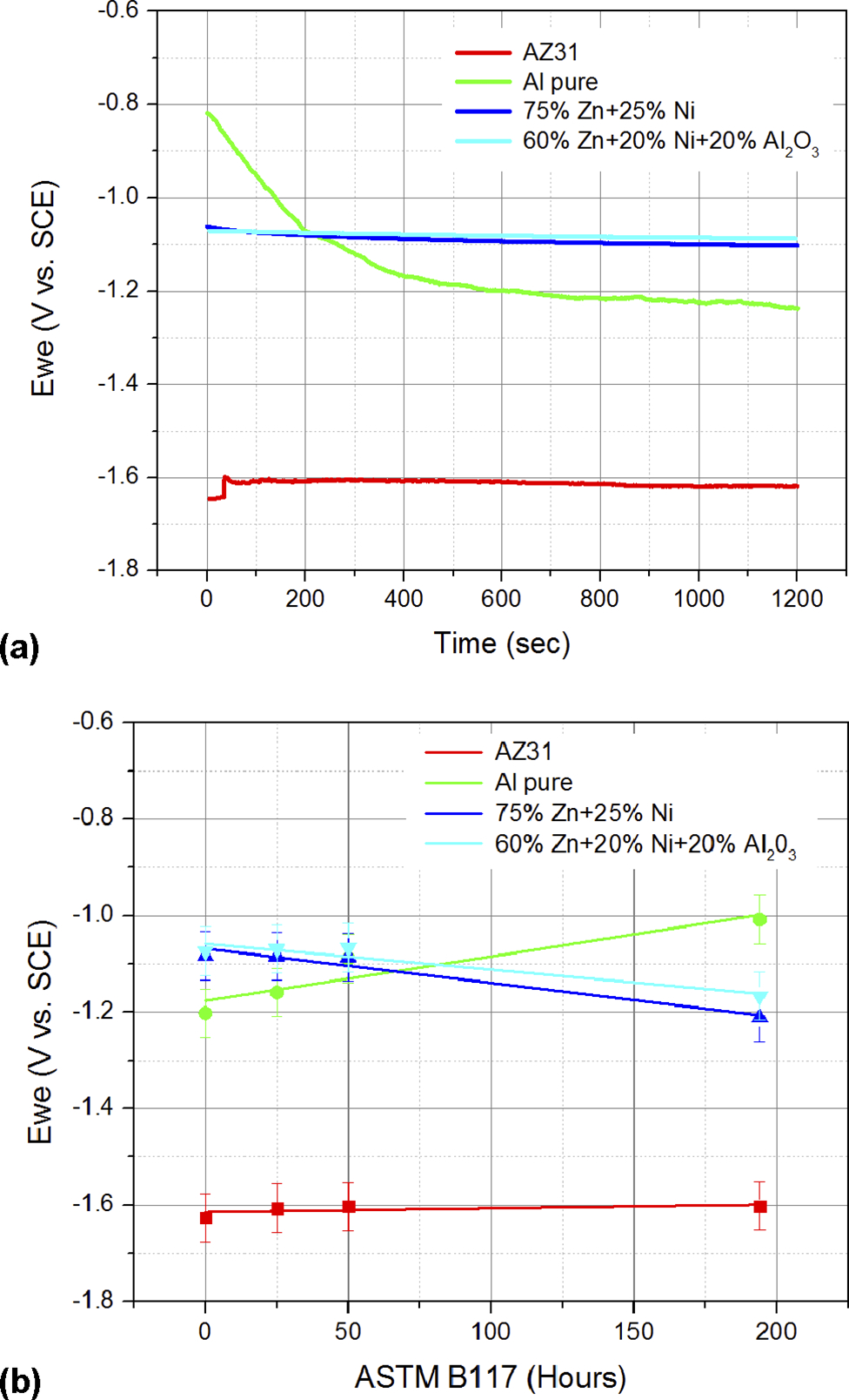
Evolution of OCP (Ewe): a Ewe versus sample immersion time in 3·5 wt-% NaCl solution; b Ewe versus time (linear regression) for samples exposed to accelerated salt fog corrosion in accordance with ASTM B117
As can be seen in Fig. 1a, after immersion in solution, the OCP of AZ31 increases, slightly drops, then reestablishes its value and finally stabilises at ∼(1600 mV. Such behaviour indicates that initially a corrosion decelerating passive film is formed, then the dissolution of the film takes place with its subsequent restoration, which is in agreement with the reported data.24,25 Another reason for the cyclic behaviour of the OCP could be associated with the variation of pH at the AZ31 surface. 26 In the conducted experiments, the pH value was recorded before and after each test. The electrolyte solution was observed to change from a neutral solution with a pH of ∼7·1 to a more basic solution with a maximum pH of 10·5. The pH increase can be attributed to the production of OH− in the electrolyte, which in turn conduces to the formation of the corrosion decelerating Mg hydroxide film in the alkaline environment. 27
The OCP of the coated AZ31 samples behaves differently from that of uncoated sample. First, the OCP of the coated samples is shifted toward noble potential values, which indicates the presence of the corrosion inhibiting layer on the surface of the AZ31 sample. The OCP of the coated samples is also dependent on the coating composition. Thus, the OCP of aluminium coated samples (PC A) shows a substantial decrease toward negative potentials within the first 6 min of immersion in the electrolyte, eventually stabilising at − 1200 mV after 15 min of immersion, which can be related to the distraction of the aluminium oxide initially formed on aluminium coatings. 28 The OCPs of the coated samples PC B and PC C display similar behaviour, demonstrating a slight shift toward nobler potentials and stabilising at 1100 mV, after 20 min of immersion in the electrolyte. It can be assumed that by providing a relatively stable OCP, the coating compositions PC B and PC C are able to slow down the corrosion reaction on the surface of AZ31 samples.
The conducted accelerated salt fog corrosion tests showed that the corrosion protection properties of the coating compositions PC A, PC B and PC C considerably differ with exposure time (Fig. 1b). The OPC of PC A samples shifts toward noble potentials, which can be attributed to the formation of a stable protective aluminium oxide film on the coating surface. 29 The OCP of PC B and PC C samples gradually decreases over the period of 200 h. The OPC decrease of PC B sample can be associated with a slow corrosion of the coating with the formation of a corrosive product ZnCl2.4Zn(OH)2. 30 Similar behaviour was observed for PC C sample. However, the CR of the sample was lower, which can be attributed to the presence of alumina in the coating composition. 29 It is important to note that corrosion resistance of all coated samples was considerably higher than that of bare AZ31 samples.
Potentiodynamic polarisation curves
The potentiodynamic polarisation curves and kinetics of the corrosion potential evolution during the accelerated corrosion test of the AZ31, PC A, PC B and PC C samples are shown in Fig. 2.
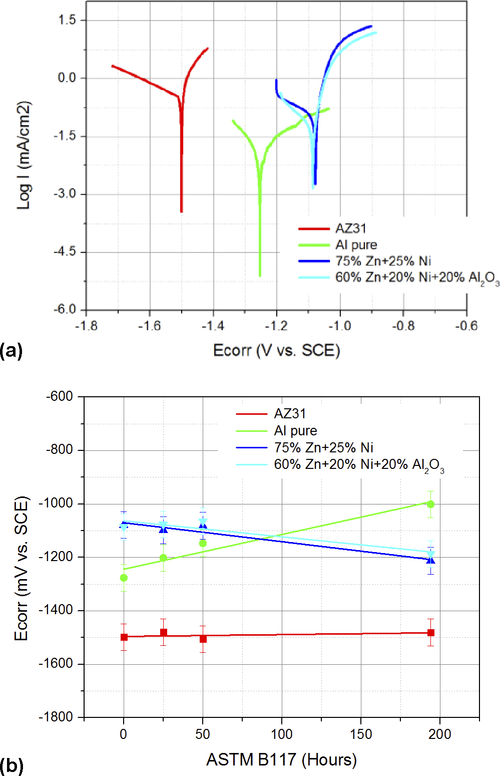
Evolution of corrosion potential (Ecorr) for investigated samples: a potentiodynamic polarisation curves; b corrosion potential Ecorr versus time (linear regression) for samples exposed to accelerated salt fog corrosion in accordance with ASTM B117
The corrosion potential and corrosion current density changes for all examined samples are shown in Fig. 2a. It can be seen that the bare AZ31 samples are subjected to corrosion much more actively than the coated samples. Such behaviour is usually associated with the interaction between AZ31 and chloride ions Cl− , which are present in the electrolyte solution. It is generally accepted that Cl− ions transform the relatively stable Mg(OH)2 into soluble MgCl2, therefore accelerating the corrosion of magnesium. 31
PC A, PC B and PC C samples are much less vulnerable to corrosion than AZ31 alloy. Slow corrosion of PC A coating can be linked to the reaction of the ionised aluminium Al3+ with chloride ions Cl− that leads to the formation of aluminium chloride AlCl3, which turns initially into aluminium hydroxide Al(OH)3 after reacting with water molecules and eventually into alumina Al203.32,33
The corrosion mechanism of coating compositions containing Ni and Zn components (PC B and PC C) may be explained by the occurrence of microgalvanic coupling between the noble Ni and the much more active Zn particles. 34 Under the influence of the corrosive environment in the presence of Cl− ions, zinc corrodes, forming preferentially Zn5(OH)8Cl2.H2O and ZnO and leaving the top layer of the coating enriched with nickel. That enriched nickel layer acts as a barrier to further corrosion. 35 The results of the Ecorr as a function of time exposed to the accelerated corrosion test ASTM B117 are shown in Fig. 2b. There are two types of corrosion behaviour that can be seen: (i) Ecorr increases with time for PC A coatings, indicating noble type, associated with the growth of the aluminium oxide film, for PC A coating; (ii) Ecorr decreases, indicating sacrificial type, associated with the slow dissolution of the Zn containing coating layer with time, for PC B and PC C coatings.
Corrosion current Icorr behaviour for the investigated samples is shown in Fig. 3. As can be seen, exposing AZ31 to salt fog corrosion environment leads to considerable increase of Icorr, which indicates that an active corrosion process takes place. 36 The Icorr for PC B samples slightly increases with the exposure time to salt fog environment, while for PC A and PC C samples the Icorr remains almost constant. It indicates that samples PC A, PC B and PC C are substantially more resistant to corrosion compared to AZ31 and can be used as corrosion protective coatings.
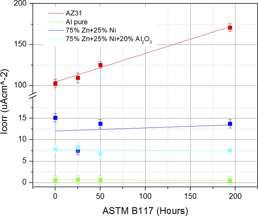
Evolution of corrosion current (Icorr) versus time (linear regression) for samples exposed to accelerated salt fog corrosion test
The corrosion behaviour of the investigated samples subjected to the accelerated salt corrosion test was also characterised by the CR (expressed in mm per year) in accordance with ASTM G102 testing procedures. The estimated CRs as a function of time in the corrosive environment for all samples are shown in Fig. 4. As can be seen, the CR of the AZ31 samples is high and substantially grows with time spent in the corrosive environment. However, the CR of the PC B samples is lower and grows with time at a much slower rate, while the rate of corrosion for PC C sample remains practically constant with time that can be attributed to the presence of alumina in the coating composition, 29 which apparently allows to deposit a denser coating structure. A denser coating may prevent the formation of microgalvanic cells between Zn and Ni grains and, therefore, increase corrosion resistance of the PC C samples. The CR for the PC A samples slightly decreases with time in the corrosive environment that can be linked to forming a stable protective aluminium oxide film.
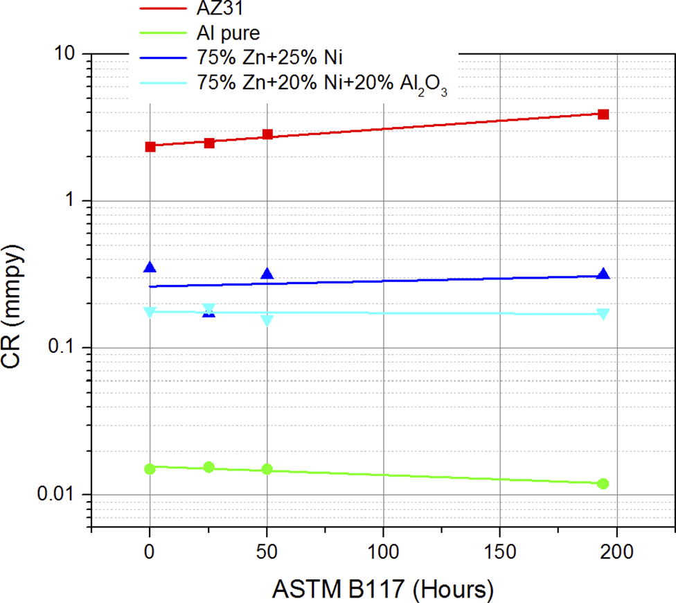
CR versus time (linear regression) for samples subjected to accelerated salt fog corrosion test in accordance with ASTM B117
It is important to note that the surface of the PC B and PC C coatings did not contain corrosion induced blisters, while the surface of the PC A coatings had a number of blisters, which was also reported by DeForce et al. 37
Coating microstructure and mechanical properties
The low porosity level and the absence of cracks at the coating/substrate interface are the major coating characteristics produced by the LPCS system. 38
However, as mentioned by DeForce et al., 37 cold spray coatings may have defects such as microcracks, micropores and voids. This fact becomes critical when coatings meet aggressive corrosive corrosion environment. In case of Cl− and OH− ions, they can easily react with magnesium substrate and create blister damage of the coating surface. From DeForce et al., 37 the minimum aluminium cold sprayed coating thickness to provide an effective barrier corrosion protection mechanism was determined to be ∼400 μm.
The SEM analysis of the coatings as depicted in Fig. 5 represents typical cold spray microstructures and reveals the presence of closed micropores at the coating interface ( < 1·0 vol.-% as measured by image analysis), whereas the rest of the coating was fully dense.
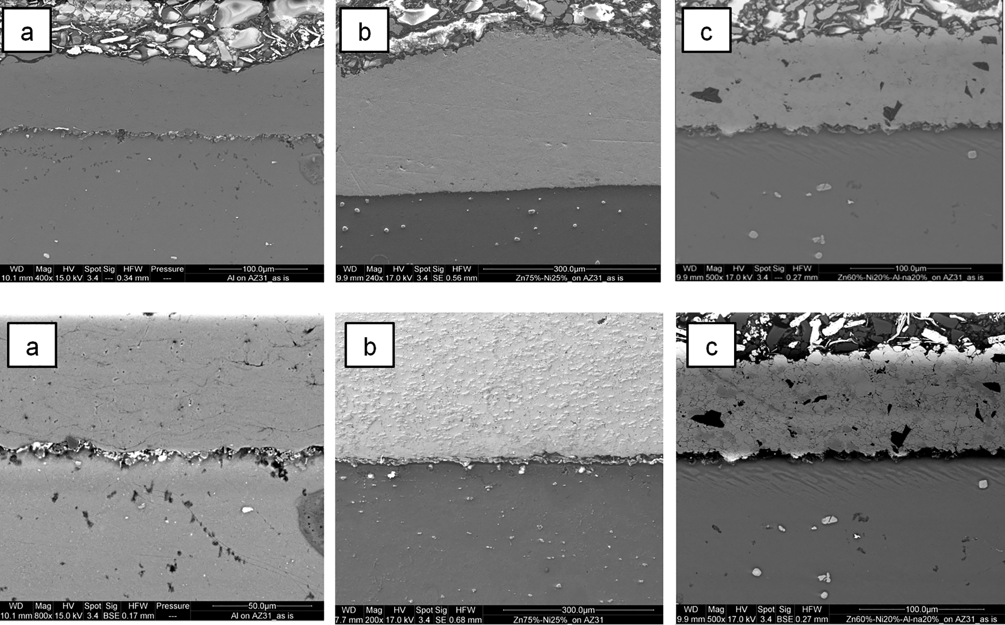
Cross-section microphotographs of coating layers cold sprayed on AZ31: a cold sprayed PC A composition; b cold sprayed PC B composition; c cold sprayed PC C composition
Adhesion strength measurements reveal that the adhesion strength for cold sprayed coating layers with the composition of PC A was 32 ± 3 MPa; however, for PC B and PC C, there were slight increases in the value up to 37 ± 2 MPa and 40 ± 1 MPa respectively. The increase in adhesion strength is proportional to an increase of the content of ‘hard’ material within the ‘soft’ coating composite matrix. This is in agreement with Dzhurinskiy et al., 29 where an increase of Al2O3 in PC leads to the increase of adhesion strength. In addition, the following should be noted from adhesion test measurements that in most cases (PC B and PC C), the failure type was cohesive, indicating that the true adhesion strength of those coatings must be greater.
Microhardness and tribological properties
The microhardness measurement results from Fig. 6 reveal that the bare AZ 31 material has microhardness of 110 MPa and elasticity modulus of 52 GPa. The elasticity properties of coating have to be matched to the substrate material to prevent the mismatch of elastic strains during loading. 39 From this viewpoint, the PC C coating composition looks more preferable because it has elasticity modulus of 61 GPa (near elasticity modulus of the AZ 31 substrate).
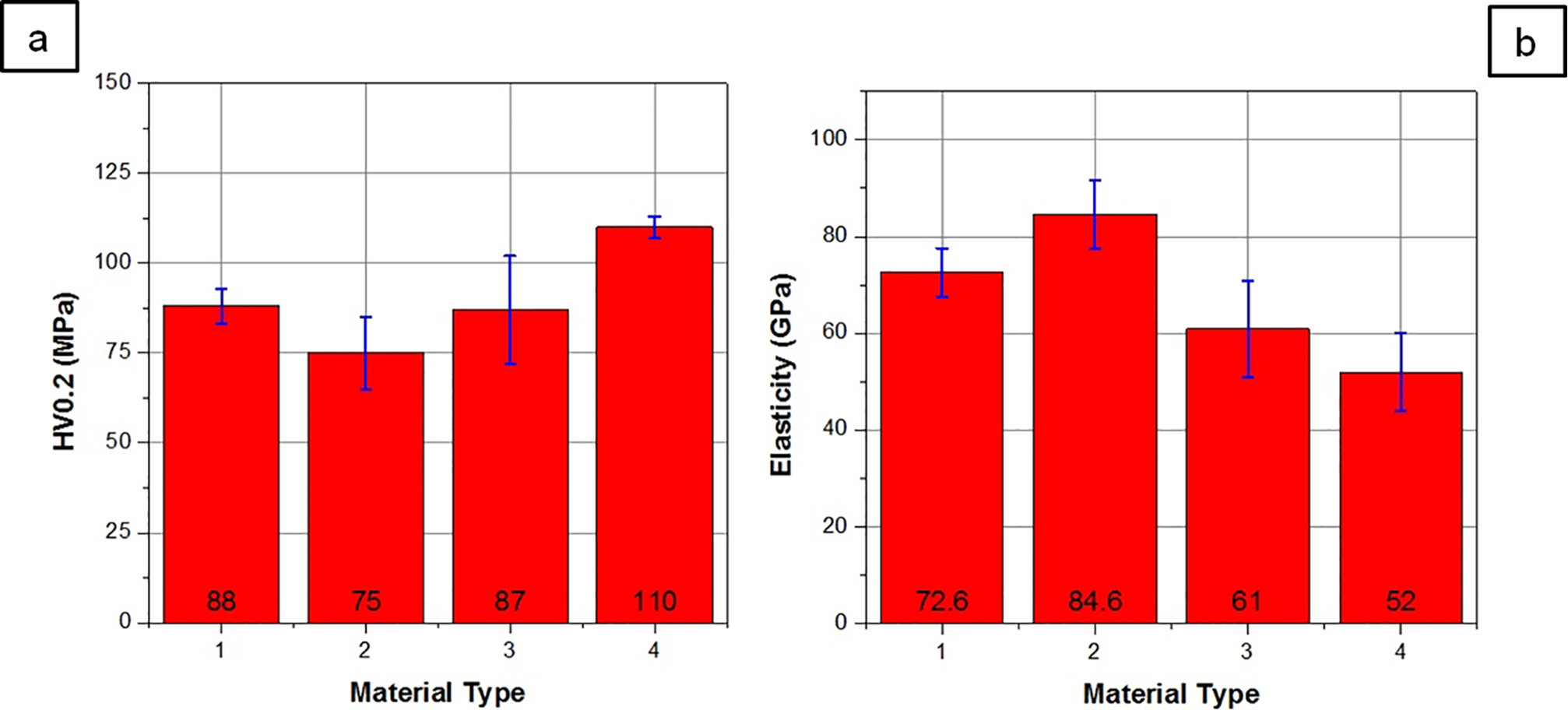
Microhardness (a) and elasticity modulus (b) of investigated cold spray compositions (1: PC A; 2: PC B; 3: PC C; 4: AZ31)
Ball on disc friction test results shown in Fig. 7 demonstrate higher friction coefficient for PC A coating as compared to that of bare AZ31 material and PC B,C coatings. The durability of the PC A coating is minimal (friction length ∼25 m before seizure). One have to note that the durability of AZ31 bare alloy is ∼50 m in spite of low friction coefficient (COF = 0·3). The friction behaviour of PC B coating is similar to that of PC A coating layer; however, the durability of PC C coating is five times higher than that of PC B coating due to Al2O3 reinforcement phase.
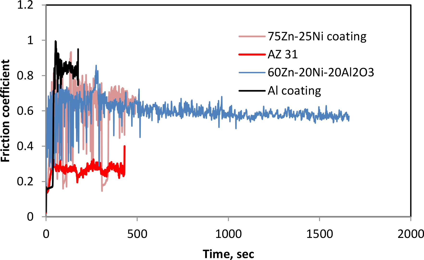
Ball on disc friction test diagrams of studied materials
From the viewpoint of mechanical joint durability, the cold sprayed composite PC C coatings demonstrate better tribological characteristics, while their corrosion properties are similar to those of Al based coatings.
Conclusion
The CR in magnesium AZ31 alloy joints is significantly reduced by the LPCS deposition of corrosion resistant 75Ni–25Zn and 60Ni–20Zn–20Al2O3 coatings. The 75Ni–25Zn and 60Ni–20Zn–20Al2O3 coating compositions show considerably better results in protecting magnesium AZ31 alloy joints from corrosion as compared to pure Al coatings. The 75Ni–25Zn and 60Ni–20Zn–20Al2O3 coatings work as a barrier between the damaging environment and the magnesium AZ31 alloy joints due to the microgalvanic action of Ni–Zn phases formed within the coatings. The 60Ni–20Zn–20Al2O3 corrosion resistant coatings demonstrate an elevated wear resistance because of the Al2O3 reinforcement phase presence.
Acknowledgements
We would like to acknowledge the financial support from NSERC (grant no. PG 445969-12) and EnWin utilities—Windsor's local distribution company.