
Abstract
TiCrN coatings were deposited onto high-speed steel substrates by arc ion plating. The crystalline structure of the coatings was analysed by X-ray diffraction. Influence of both negative bias applied to the substrates and nitrogen flowrate on the crystalline structure was investigated. Scanning electron microscopy was employed to observe the surface quality of the coatings. Hardness of the coatings was measured by the XP nanoindenter. It is indicated that both size and quantity of the macroparticles decrease with increasing negative bias. TiCrN coatings with enhanced hardness can be obtained when a larger negative bias is applied. Increasing nitrogen flowrate benefits hardness of the coatings as well. Compared with the TiN thin film, the TiCrN coatings exhibit better mechanical behaviour due to the solid solution strengthening effects caused by the doped Cr atoms. Influence of deposition parameters on the structure and mechanical properties has been discussed.
Introduction
Hard coatings, among which TiN is a representative, have been intensively applied to improve and modify surface quality of cutting tools, moulds and components of cars due to their excellent properties such as high hardness, low friction coefficient and good corrosion resistance.1–2 However, single layer is usually not qualified to modern machining environment, where comprehensive mechanical properties of the tools are required. Therefore, complex coatings such as TiMN, where M represents another metallic element, have gradually drawn intensive attention from industries.3–4 For example, high temperature oxidation resistance and hardness of TiN film can be greatly enhanced when Al and Si atoms are doped.5–6 Boron, when doped, may improve thermal stability of the TiN film. 7 TiCrN has been attracting more attention owing to its high hardness, high temperature oxidation resistance and low friction coefficient.8–9 It is well known that properties of the film are mainly determined by microstructure such as phase, grain and defect structure, which are dependent on the deposition parameters. In general, TiCrN films can be fabricated by reactive magnetron sputtering, ion beam assisted deposition, cathodic arc or electron beam evaporation. Among these methods, arc ion plating is the most popular one to prepare the films with large area uniformity and strong adhesion in industry. Although there are many research works regarding the structural and mechanical properties of TiCrN films, few studies reported the influence of the nitrogen flowrate on microstructure and mechanical properties of the TiCrN films.
In this work, TiCrN films were fabricated by arc ion plating, and the influence of both the nitrogen flowrate and the negative bias on structure and properties of the films is studied. The mechanism of property improvement of the compound TiCrN film with respect to those of TiN film is discussed by measuring and analysing the mechanical properties.
Experimental
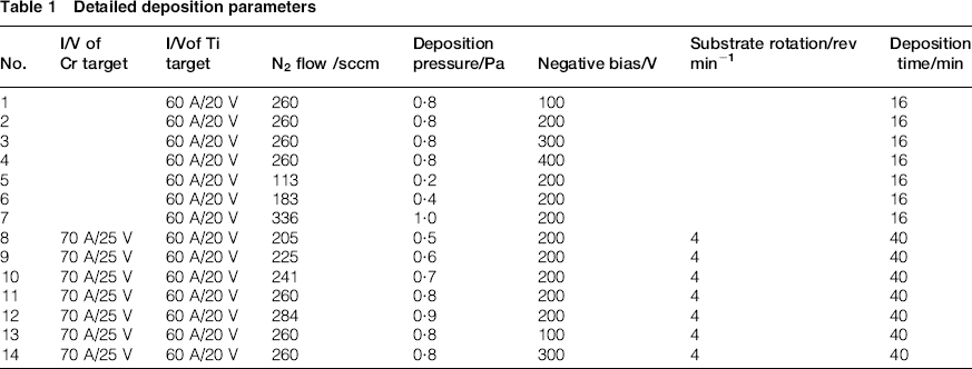
The substrate was high-speed steel W18Cr4V with a dimension of 15 mm × 10 mm × 10 mm, and it was ground and polished manually until its surface was mirror-like. It was strictly cleaned and dried before being put into the deposition chamber. The background vacuum was pumped to 3 × 10− 3 Pa, and then argon was inflated. As a negative bias of ∼1000 V was applied onto the substrate, glow discharge was triggered to deeply clean the surface under a pressure of 0·16 Pa for ∼3 min. Both TiN films and TiCrN films were fabricated at different biases for comparison. Detailed experimental parameters are illustrated in Table 1. The deposited films were taken out after they are cooled to room temperature in order to suppress internal stress within the film. 10
Detailed deposition parameters
Thickness of the films was measured by the XP-2 profiler. The XP nanoindenter was employed to test hardness and elastic modulus of the films. Surface morphology was observed by Shimadzu SSX-550 scanning electron microscopy (SEM), and the microstructure of the films was characterised by X-ray diffraction (XRD), where Kα rays of copper target were produced using an accelerating voltage of 40 kV.
Results and discussion
Deposition rate
For a given deposition time, thickness of the films reflects deposition rate. Therefore, deposition rate is calculated by dividing the thickness with the deposition time in this work. Thickness of the films was measured by the profiler. Each film was measured three times, and the average value was granted as the thickness. Figure 1 shows thickness of all the films. The thickest TiCrN film was numbered 11, which was fabricated with 260 sccm nitrogen flowrate and 200 V negative bias. Its thickness was 1240 nm. The thinnest TiN film, with a thickness of only 566 nm, was obtained at 260 sccm nitrogen flowrate and 100 V negative bias. According to Fig. 1, thickness (i.e. deposition rate) of the films depends not only on the nitrogen flowrate but also on the bias applied to the substrates. For increasing nitrogen flowrate, the deposition pressure increases and collisions between the nitrogen molecules and the evaporated metallic atoms become more frequent. This process helps to form nitride of the metal. At low biases, the ions have low energy and would be readily scattered and their directional movement to the substrate is inhibited. On the contrary, under high biases, the ions may get enough kinetic energy and tend to directly move to the substrate, resulting in a rapid deposition.
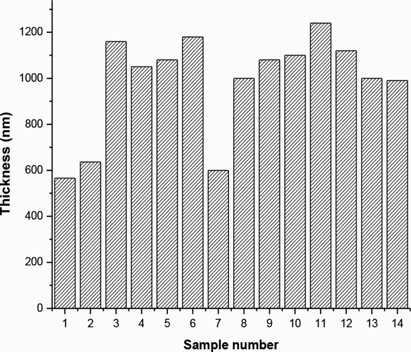
Thickness of films
Surface morphology
Surface morphology of both TiN and TiCrN films was observed by SEM at different bias and nitrogen flowrate. The results are shown in Fig. 2, where many white macroparticles are observed on the surface of the films. These inhomogeneous macroparticles came from the melted spots, which were caused by the high temperature arc on the target surface.11–12 Some macroparticles are immersed in the film, some are inlayed, and some are attached to the film surface, depending on when they are deposited. 13 The macroparticles not only reduce the brightness but also play down the properties of the films, 14 inhibiting further development and application of AIP from fabrication of nanocoatings and functional films. Many craters can be observed in Fig. 2. They are formed when the macroparticles that are not tightly adhesive to the surface are detached by ion bombardment.15–16
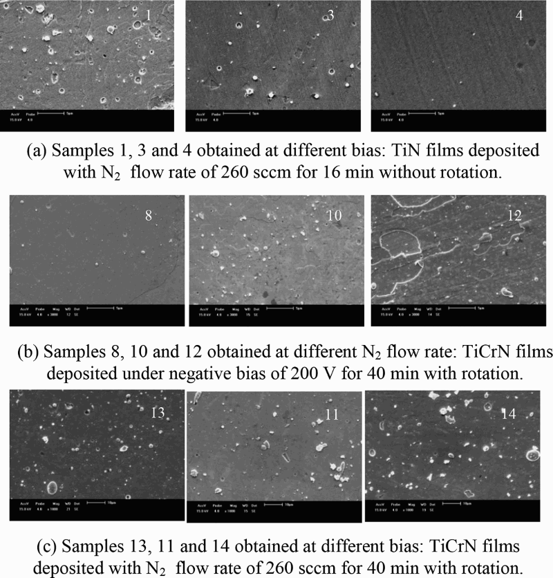
Surface morphology of TiN and TiCrN samples: a samples 1, 3 and 4 obtained at different bias: TiN films deposited with N2 flowrate of 260 sccm for 16 min without rotation; b samples 8, 10 and 12 obtained at different N2 flowrate: TiCrN films deposited under negative bias of 200 V for 40 min with rotation; c samples 13, 11 and 14 obtained at different bias: TiCrN films deposited with N2 flowrate of 260 sccm for 40 min with rotation
Fig. 2a gives the results of TiN films deposited at various biases. The three pictures (from left to right) correspond to sample nos. 1, 3 and 4 in Table 1 respectively. It illustrates that both quantity and size of the macroparticles decrease with increasing negative bias of the substrate. The melted spots in the vacuum plasma can be considered as dust particles, and their surfaces have negative charges. When they approach the substrate surface, which is also negatively biased, a repulsive force is generated, preventing them from falling onto the film surface. The higher the negative bias, the larger the repulsive force. That is why one can get less macroparticles on the film surface using a larger bias.
Surface morphology of TiCrN films deposited with different nitrogen flowrate and with different bias is displayed in Fig. 2b and c respectively. Figure 2b shows that the TiCrN films tend to grow by layer spreading mode as the nitrogen flowrate increases. Obvious stages, indication of incompletion of layer growth, can be obviously observed in the film sample obtained at 284 sccm nitrogen. By comparing Fig. 2a and c, one can see that the negative bias has less effects on the morphology of TiCrN films than that of TiN films. In Fig. 2c, little difference exists in the surface morphology of the samples fabricated under bias of 100, 200 and 300V respectively. This may be ascribed to the high melting point (1875°C) of Cr, which is higher than that (1668°C) of Ti. The size of Cr dusts is relatively smaller, and there has less negative charges on their surface. As a result, the repulsive force from the substrate cannot effectively prevent the dusts falling onto the film surface.
Crystalline structure
The crystalline structure of the films was analysed by XRD. Figure 3a exhibits the XRD results of the TiN films deposited with different nitrogen flowrate. As can be seen, cubic TiN was formed. As nitrogen flowrate is < 260 sccm, several peaks of TiN film can be observed on the pattern. In case of 336 sccm nitrogen flowrate, only the Fe (110) peak can be apparently observed, indicating that the diffraction intensity is too weak due to the thinnest thickness as indicated in Fig. 1. The influence of bias on crystalline orientation is shown in Fig. 3b, where planes (111), (220) and (222) of TiN film can be observed. The preferred orientation of TiN film changes from (111) to (220) when bias voltage increases from 100 to 400 V.
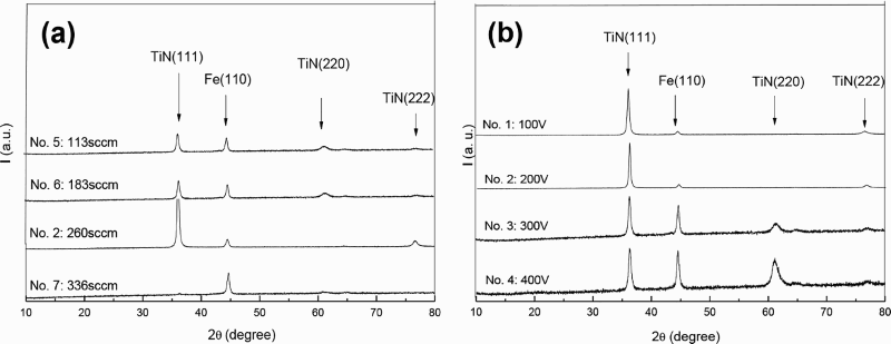
XRD spectra of TiN films obtained with different a nitrogen flowrate and b negative bias; sample number is indicated besides each spectrum
Fig. 4 gives the XRD results of TiCrN films that were deposited with different nitrogen flowrate and bias. It indicates that the TiCrN films keep the face-centred cubic structure of TiN. Compared with the XRD spectra of TiN, the relative intensity of peak (220) of TiCrN is enhanced, and the width of the peaks is broaden due to the additionally formed CrN and Cr2N phases, which have similar lattice constants to that of TiN. CrN and Cr2N phases are formed when the solubility of Cr in lattice of Ti is saturated.
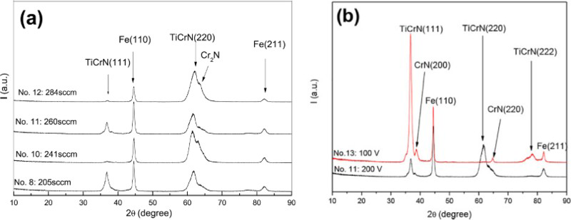
XRD spectra of TiCrN films obtained with a different nitrogen flowrate and b different bias; sample number is indicated besides each spectrum
Mechanical properties
Hardness and elastic modulus of both TiN and TiCrN films were measured by a nanoindenter, and the results are shown in Fig. 5. It indicates that the mechanical properties of the films depend on the negative bias applied to the substrate and on the nitrogen flowrate during the deposition process. An apparent conclusion is that the average hardness or elastic modulus of TiCrN films is higher than that of TiN films, indicating that the Cr atoms doped into TiN improve its mechanical properties. Doping Cr into TiN may result in smaller granular that forms the film, as indicated by previous XRD data (see Fig. 4b). According to the Hall–Petch formula, hardness of the films increases with reducing size of granular. Another strengthening mechanism may be employed to explain the results. As atomic diameter of the substituting Cr is different from that of the substituted Ti, lattice distortion occurs and the internal stress makes the value of hardness and elastic modulus increased.
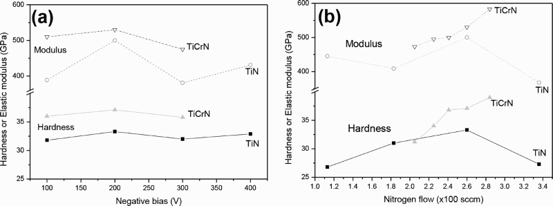
Hardness and elastic modulus of TiN and TiCrN films as function of a negative bias and b nitrogen flowrate
Conclusion
Both TiCrN and TiN films were fabricated by arc ion plating with different nitrogen flowrate and different bias applied to the high-speed steel substrate. The microstructure and mechanical properties of these films were measured and analysed. The following conclusions can be drawn:
Both nitrogen flowrate and substrate bias influence the deposition rate of TiCrN coatings. Increasing flowrate and bias usually results in a rapid deposition of the films. TiCrN film tends to grow in layer spreading mode with increasing nitrogen flowrate. Negative bias has little effects on the surface morphology of TiCrN films. The preferred orientation of crystalline plane of TiCrN films can be controlled by the nitrogen flowrate and negative bias applied to the substrate. Owing to the doped Cr, TiCrN films have enhanced mechanical properties compared with TiN films.
Footnotes
Acknowledgements
This work was supported by the NSFC (grant no. 51472180) and the Innovation Project of Tianjin Normal University (grant no. 52X09038).