
Abstract
Experimental investigations were carried out in order to evaluate the possibility of using warm spray as a repair technique for steel components. A high velocity oxygen fuel system was modified to deposit an AISI 316 stainless steel feedstock powder in solid state. A preliminary study was carried out on the spray conditions to optimise the deposition process. The powder was deposited on a steel sample, and the quality of the coating was evaluated by optical microscope observations: a limited porosity was observed in the repair. Test damage was produced in another steel sample and was repaired by warm spray. Residual stresses and microhardness of the repaired area were measured. It was found that beneficial compressive residual stresses were produced in the repaired area, which also exhibits a good microhardness, slightly higher than that of the substrate. Finally, adhesion tests were carried out, and a strength >46 MPa was found.
Introduction
Warm spray (WS) is an emerging spray coating technology,1–3 recently developed in order to cover the existing gap between the conventional high velocity oxygen fuel (HVOF) process and the relatively new cold spray (CS) technique. Warm spray is a modification of HVOF: by injecting additional nitrogen gas into the combustion chamber of the HVOF torch, the flame jet temperature can be controlled and can be kept lower than in the standard HVOF process. Therefore, the powder particles can be heated at a temperature lower than their melting point but higher than that in the CS process. The lower temperature of WS, as compared to HVOF, also prevents chemical reactions of the feedstock powder. This advantage is particularly important for those coatings that oxidise or deteriorate rapidly at high temperatures. 1 On the other hand, certain advantages can also be expected when comparing WS with CS. Several studies4–6 proved that the successful bonding of a solid impacting particle in CS requires localised deformation and adiabatic shear instabilities, which occur at an impact velocity higher than the so called critical velocity vcrit. Not only in CS but also in WS that the powder particles remain solid during spraying, although the higher temperature and the higher velocity make the particles more deformable. As a consequence, it is reasonable to suppose that denser coatings with lower porosity and higher performance can be produced using WS. Until now, WS has been used for coatings that were difficult to obtain by CS, such as titanium alloys, WC–Co and several superalloy coatings.7,8 Eliminating the detrimental effects of high temperatures on coating and substrate properties, recently CS was successfully used to repair damage in light alloy 9 and in cast iron 10 components instead of welding. The possibility of using CS to repair steel components was recently evaluated through laboratory tests, and some good results were obtained. 11 It was found that CS does not introduce thermal tensile residual stresses and does not alter the base metal as what happens when welding is used. Therefore, a heat treatment is not required after the repair. This leads to cost reductions and eliminates the distortion risk, which could compromise the possibility of component reuse. Environmental pollution due to the post-weld heat treatment is also eliminated. Similar results could be obtained using the WS process, thanks to the similarity of these techniques. This procedure could become useful for restoring the original profile of damaged areas in steel components, in particular of those parts that have a high cost, such as turbine components. No research studies on the use of steel coatings obtained by WS to repair steel components have been found in the existing literature. The aim of this research is to evaluate the possibility of using an AISI 316 stainless steel coating obtained by WS to repair steel components. An HVOF system was modified, and the spray conditions were optimised for the WS deposition of the stainless steel powder. In some recent papers,12,13 it was observed that the spray conditions, in particular the nitrogen flowrate and thus the particles temperature, have a major impact on both microstructure and mechanical properties of titanium coatings deposited by WS; therefore, similar effects can be expected in the case of steel coatings. The following investigations were carried out on various steel samples coated by WS: metallographic observations, residual stresses measurements, microhardness and adhesion tests.
Materials and experimental procedures
An HVOF MET JET 3 system was modified to deposit a steel feedstock powder in solid state.
A commercially available AISI 316 austenitic stainless steel powder (AMPERIT 377·074 45/15), with nominal size range of 15–45 μm, was used in the experiments. The nominal chemical composition of the powder is 17%Cr, 11%Ni, 2·5%Mo, < 1%Si, 0·05%C and Fe balance.
An austenitic stainless steel powder was chosen because this phase is soft and easily deformable, as observed in a previous study carried out by the authors on a CS repair. 11 Moreover, this alloy is more oxidation resistant than other metal powders like titanium, which can react with the combustion gas and the surrounding air during the process, producing undesirable thick oxides. These oxides act as a barrier reducing the bonding between the powder particles and the substrate or the particles themselves, lowering the adhesive strength of the coating. 12 The morphology of the as received powder is shown in Fig. 1.
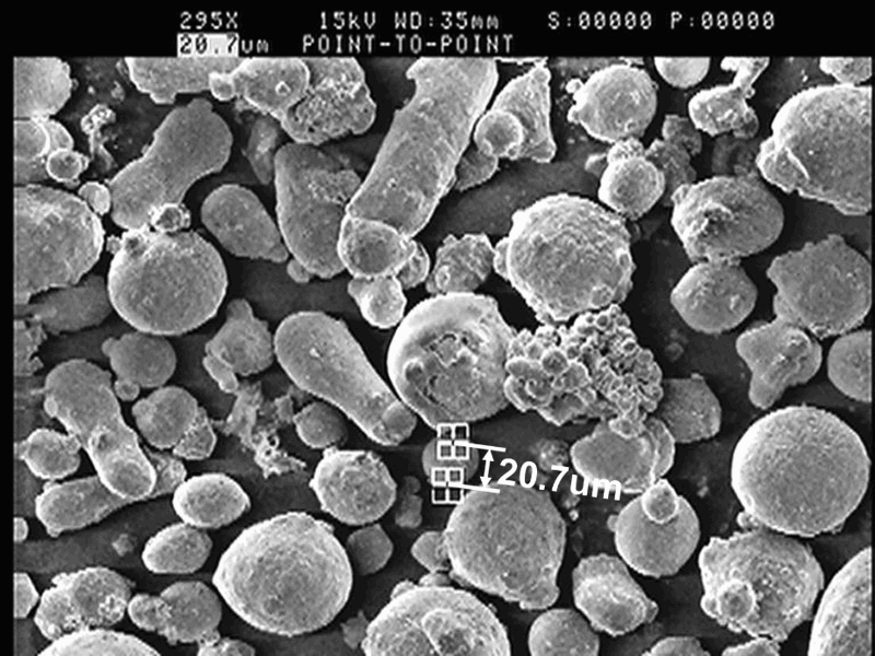
Morphology of as received AISI 316 feedstock powder
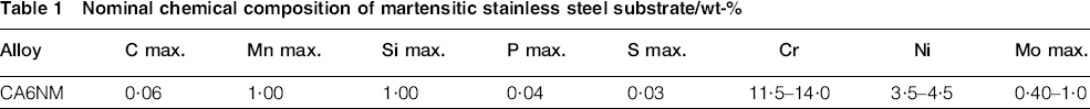
The base metal was an ASTM A743 grade CA6NM cast martensitic stainless steel, widely used for large cast components in the hydroelectric sector. Its chemical composition is shown in Table 1.
Nominal chemical composition of martensitic stainless steel substrate/wt-%
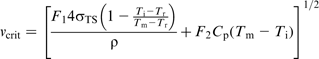
Since in WS the temperature, and thus the plasticity of the particles, increases as the nitrogen flow decreases, influencing the quality of the coating, a preliminary study on the spray conditions was carried out in order to optimise the deposition process. It is well known4–6 that the successful bonding of a solid impacting particle requires localised deformation and adiabatic shear instabilities, which occur at an impact velocity v higher than the so called critical velocity vcritical. The critical velocity decreases as particles temperature increases because the particles become more deformable. The particles sprayed with a velocity lower than the critical velocity are not able to adhere to the substrate, so they rebound from it. Repeated impacts cause the deformation and the erosion of the substrate. Furthermore, the particles sprayed with an excessive velocity (v>verosion) cannot adhere to the substrate because of the excessive impact kinetic energy, and again, they produce a substrate erosion, resulting in a weight loss. Critical and erosion velocities of the powder were calculated using the equation proposed by Schmidt et al.
14
Two samples (50 × 20 × 5 mm) were machined out of the steel block. The first substrate was sandblasted in order to improve the adhesion strength of the coating. A commercial white corundum grit of 0·6–0·7 mm diameter and a blasting pressure of 0·6 MPa were used. Afterwards, the sample was coated by WS; the coating thickness was 1·5 mm. Later, it was cut orthogonally to the coated surface; the cross-section was ground and polished mechanically with diamond suspension to a 1 μm finish. A metallographic observation was carried out with a Reichert-Jung MeF3 optical microscope to investigate the quality of the coating. The porosity of the coating was measured according to ASTM E2109-01. The measurements were performed on × 200 magnification images by averaging several micrographs.
The second sample was damaged, making a drill hole. The carving has a diameter of 10 mm and a maximum depth of 3 mm. Then, this sample, too, was sandblasted, and the damaged area was repaired using WS. After the repair, the sample was ground in order to remove the excess material on the repaired surface. A vitrified bonded aluminum oxide wheel was used, having a diameter of 115 mm and abrasive grain size number of 60. The grinding wheel speed was between 4·4 and 5·2 rev min− 1. The repaired surface was polished with diamond suspension to a 1 μm finish, and Vickers microhardness tests were carried out by a Shimadzu microhardness tester type M, using a load of 500 g and a loading time of 15 s. The measurements were taken across the repaired area along its diameter. A residual stress depth analysis was then carried out in the repaired area of this sample. A layer removal method was chosen, which has no influence on the residual stress distribution, consisting of a series of electrochemical etchings. Each etching removed a layer of 0·1 mm and created a new surface, on which residual stresses were measured in longitudinal and in transversal directions. The residual stresses were measured by X-ray diffraction using an Enixe diffractometer, equipped with a Cr tube. The radiation used was Kα1 (λ = 0·22897 nm). The incoming beam was collimated with 1 mm diameter cylindrical capillary. The instrument was equipped with a position sensitive detector. The detector, with a vanadium filter for Kβ, is a one-dimensional sensor that can measure the X-ray as a function of the angular position. The 2θ angular range covered by the detector is 40°. The stress was measured using the reflection plane {220} and a counting time of 45 s. The Ψ range tilting was ± 40°, the number of Ψ angles was 9. The data were analysed using the Xenia software. The peak positions were determined by pseudo-Voigt fits with a polynomial correction for background, absorption and Kα2 radiation. According to ASTM E2860-12, the X-ray elastic constants were S1 = − 1·56 × 10− 6 MPa− 1 and 1/2S2 = 6·05 × 10− 6 MPa− 1.
Finally, six cylindrical samples, having a diameter of 25 mm and a height of 38 mm, were extracted from the steel block in order to carry out three adhesion tests, according to ASTM C633. The end of three samples was sandblasted and coated by WS following the same procedure and using the same parameters adopted for the previous samples. The coating thickness was 0·3 mm. The coated surfaces were cleaned and were bonded to the uncoated ends of the other samples using an adhesive bonding agent (Loctite Hysol 9497 a&b), three specimens for the adhesion tests were obtained. The tests were carried out by means of a servohydraulic testing system. An increasing tensile load was applied at a constant rate of crosshead travel equal to 0·78 mm min− 1 until rupture occurred. The maximum load applied was recorded. The adhesion strength was calculated as maximum load/cross-sectional area of the specimen for all tests, and the average value was computed.
Results and discussion
The understanding of the adhesion mechanisms of the powder particles to the substrate and the identification of the best spray conditions are key problems in the development of new spray deposition techniques. In the present paper, there is no investigation on the powder adhesion mechanisms, but a preliminary study on the spray conditions was carried out in order to optimise the deposition process. The critical velocity and the erosion velocity versus the temperature of the powder particles are shown in Fig. 2. Figures 3–5 show the deformation state of various sprayed particles and the surface morphology of the substrate material in conditions 1–3 of Fig. 2 obtained by varying the nitrogen flow, according to the model developed by Kuroda et al. 1 Few particles sprayed using a high nitrogen flow coupled with a low temperature (condition 1 of Fig. 2) adhered to the substrate, most of them rebounded from the substrate and the impact produced the round indentations shown in Fig. 3. Figure 4 shows one of the many unmolten particles that adhered to the substrate material thanks to a good combination of nitrogen flow and particle temperature (condition 2 of Fig. 2). Finally, the splat of Fig. 5 revealed that the particle experienced a completely molten state during spraying, as in a traditional HVOF process, due to the absence of the nitrogen flow and to the high particle temperature (condition 3 of Fig. 2). The results of this preliminary study indicate condition 2 as the best spray condition because the particles adhered well to the substrate material, and this condition was chosen to deposit the powder on all samples.
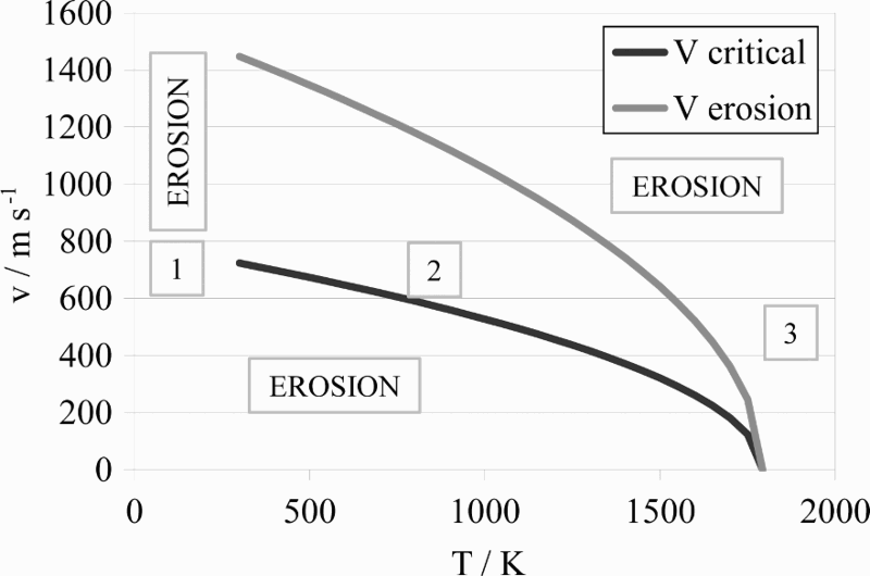
Critical velocity and erosion velocity versus temperature of feedstock particles
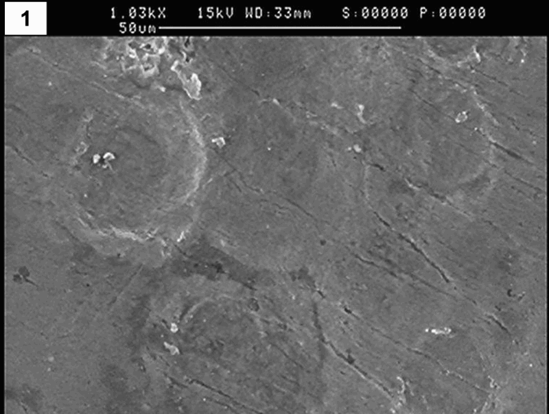
Image (SEM) of indentations produced on substrate by powder particles sprayed in condition 1 of Fig. 2
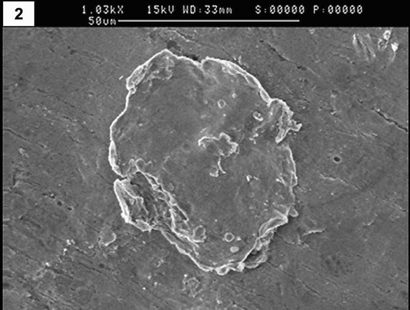
Image (SEM) of deformed powder particle sprayed on substrate in condition 2 of Fig. 2
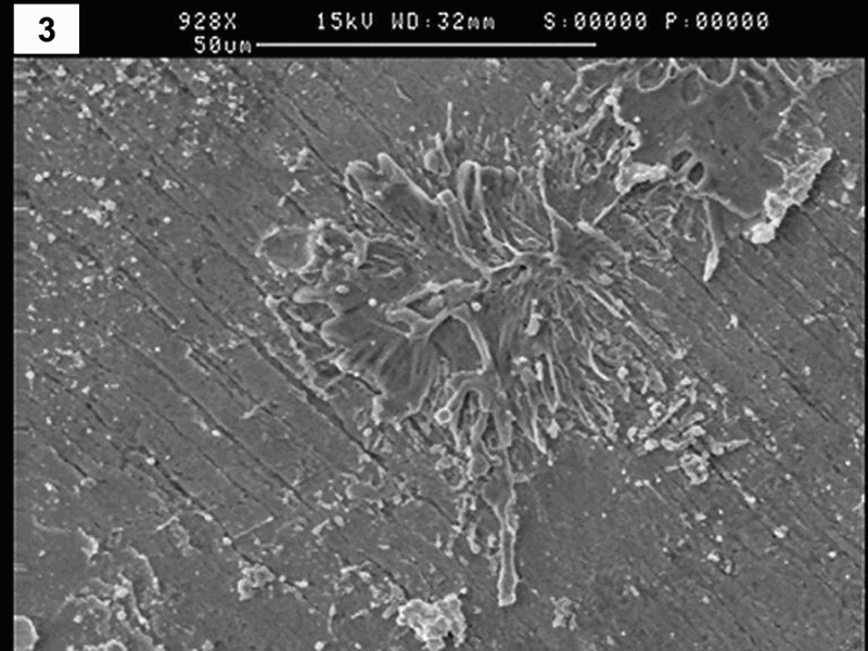
Image (SEM) of splat obtained on substrate spraying powder in condition 3 of Fig. 2
The cross-section of the first coated sample is shown in Fig. 6. The coating is clearly visible because it is lighter than the substrate material. It is worth noting that the coating is uniform and dense, with a few small pores located at the coating/substrate interface and a very limited porosity within the repair (∼1%). This result confirms that the sprayed particles reached a high enough temperature and velocity to be deformed well during the impact with the substrate and with the already deposited particles. The porosity of the coating is lower than that observed in an AISI 316 repair of a damaged CA6NM cast martensitic stainless steel sample obtained using CS, previously studied by the authors. 11 This result was obtained thanks to the higher powder temperature reached in WS than in CS, which increases the plasticity of the particles and leads to a denser coating.
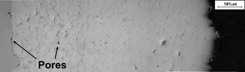
Cross-section of WS coating
Figure 7 shows the microhardness as a function of the distance from the centre of the repaired area measured on the second sample. The microhardness varies between 297 and 324 HV0·5: it is affected by the impact velocity of the solid particles and the accompanying deformation process that leads to a strain hardening phenomenon. The microhardness of the substrate ranges between 260 and 274 HV0·5. Therefore, the microhardness of the repaired area is slightly higher than that of the substrate metal, but this is not critical because the austenitic stainless steel has a high toughness and does not undergo a toughness reduction at decreasing temperatures.
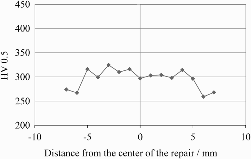
Microhardness measured on ground and polished surface of repaired sample
Figure 8 shows the residual stresses as a function of the distance from the repaired surface, measured in the depth of the second sample. The residual stresses are affected in the first 100 μm from the surface by the grinding and the polishing operations; therefore, the values measured in this zone are not significant. An almost constant value of − 400 MPa was measured in the longitudinal direction, whereas a slight increase in the residual stresses from − 450 to − 330 MPa with increasing distance from the surface was measured in the transversal direction. It is worth noting that the residual stresses are compressive both in the longitudinal and in the transversal directions. The compressive residual stresses inside the repaired area are due to the complex deformation conditions during the particles impact on the surface and on the already deposited particles. Residual stresses close to the surface of engineering components have a significant effect on their fatigue life: tensile residual stresses tend to accelerate the nucleation and growth of a fatigue crack, while compressive residual stresses are usually appreciated since they result in an improvement in the fatigue strength of the material. Welds are a major source of detrimental tensile residual stresses, so a post-weld heat treatment is required in order to relieve the residual stresses and restore the properties of the base material. 15
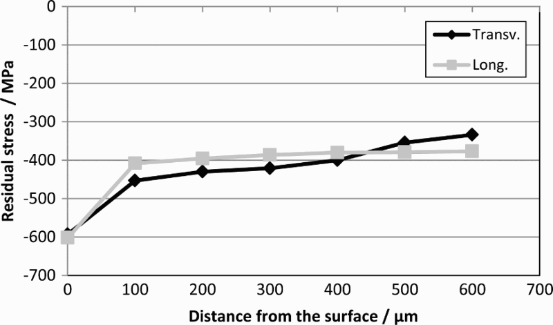
Residual stresses in repaired sample as function of distance from surface
Finally, the load–displacement curves obtained by the adhesion tests are shown in Fig. 9. The failure of the samples was entirely at the coating/bonding agent interface. This result indicates a good bond between the coating and the substrate material and also a good cohesion of the sprayed particles inside the coating. The adhesion strength of the coating was calculated as maximum load/cross-sectional area of the specimen for all tests; the average value was higher than 46 MPa.
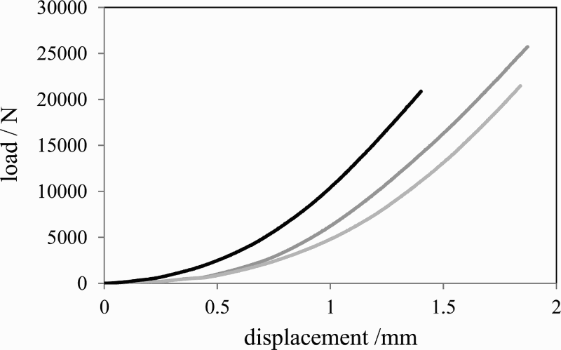
Load–displacement curves of adhesion tests
Conclusion
The possibility of using WS AISI 316 stainless steel coatings to repair steel components is presented, supported by satisfactory results obtained from metallographic observations, residual stress analysis, microhardness and adhesion tests carried out on coated samples. The metallographic observations showed that a dense coating can be obtained, with few small pores located at the coating/substrate interface and a very limited presence of porosity within the coating. Compared with an AISI 316 repair deposited by CS previously studied by the authors, it was found that WS lead to a lower porosity level within the coating, giving a better quality of the repair.
The compressive residual stresses induced in the repaired area during the powder deposition have a beneficial effect, since they result in an improvement of the component fatigue strength. The microhardness of the repaired area is slightly higher than that of the base metal; this property does not lead to any problem because the austenitic stainless steel has a high toughness and does not undergo a toughness reduction with decreasing temperature. Finally, a good adhesion strength of the WS coating was measured.
Footnotes
Acknowledgements
The authors wish to thank Mrs V. Ferrari for her collaboration in carrying out the adhesion tests.