
Abstract
For a comprehensive understanding of the scientific relations between composition, microstructure and properties of hard coatings usually a multitude of deposition runs is necessary. Within the present work, a combinatorial deposition approach using triangular shaped segmented sputter targets was adapted for an industrial scale sputter system. Owing to the position of the substrates relative to the target segments, a wide range of compositions can be achieved within a single deposition run. To verify this concept, Cr1 − xAlxN reference coatings and Ta1 − xAlxN coatings, each with a base layer of TiAlN (i.e. a bilayer configuration), were synthesised. The effect of the varying chemical compositions on the structure and mechanical as well as tribological properties was investigated. This approach enables to efficiently identify promising coating compositions.
Introduction
Ternary transition metal nitride hard coatings have attracted enormous interest owing to the synergistic influence of the individual elements on their properties. TiAlN is one of the most popular members of the family of ternary hard coatings for cutting tools. Recent research has further contributed to expand this family.1–9 However, to obtain the optimal coating characteristics, it is mandatory to investigate the effect of the relative concentrations of the individual components on structure and properties of these coatings. Traditionally, they are deposited from composite targets or from individual elemental targets, where multiple deposition runs have to be carried out. To minimise the number of deposition runs, a combinatorial deposition process 10 has been adopted in the present work with the design of triangular shaped segmented targets for industrial scale sputter systems. This target configuration has been shown in an earlier publication on Cr1 − xAlxN 11 to result in coatings with varying compositions relative to different substrate positions in a single deposition run. To prove the validity of this concept for other coating materials, Cr1 − xAlxN reference coatings and Ta1 − xAlxN coatings were deposited with a base layer of TiAlN (henceforth referred to as Cr1 − xAlxN and Ta1 − xAlxN bilayer coating respectively). The effect of varying chemical compositions on structure as well as mechanical and tribological properties of the coatings was investigated.
Experimental
Coating deposition
Cr1 − xAlxN and Ta1 − xAlxN coatings, each with a base layer of TiAlN providing adhesion and mechanical support, were deposited by reactive unbalanced magnetron sputtering in an industrial scale CemeCon CC 800®/9MLT system. This system is equipped with four bipolarily pulsed magnetrons. As indicated in Fig. 1, two composite TiAl targets of size 500 × 88 mm2 consisting of 60 at-%Al and 40 at-%Ti were fixed on one cathode pair. On the other cathode pair, Cr and Al (for the Cr1 − xAlxN bilayer) or Ta and Al (for the Ta1 − xAlxN bilayer) targets, with triangular shape and a size of 200 × 88 mm2, were arranged as shown in Fig. 2b. All targets were produced by powder metallurgical methods.
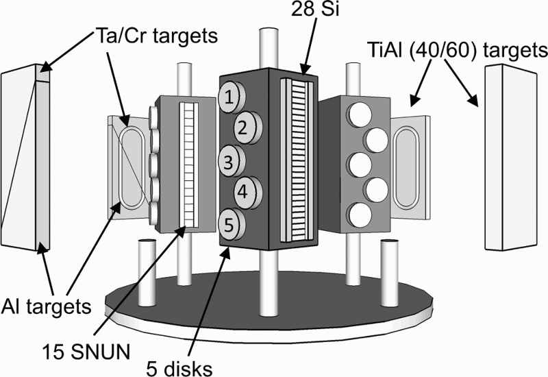
Schematic of industrial scale sputtering system with four magnetrons, indicating arrangement of substrates on carousel with respect to targets
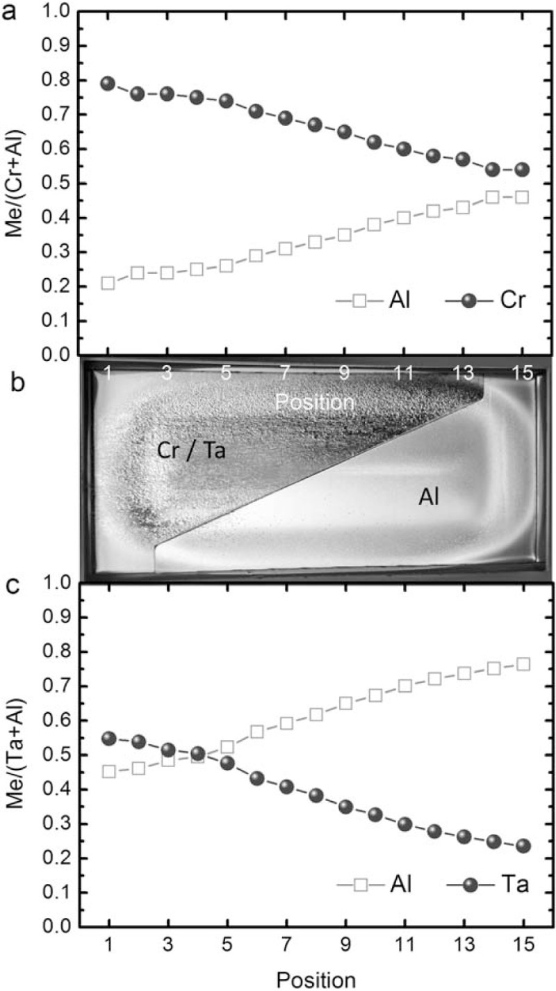
Me/(Cr+Al) atomic ratios of a Cr1 − xAlxN and c Ta1 − xAlxN bilayers correlated to b arrangement of triangular shaped segmented targets
The coatings were deposited on cemented carbide (11 wt-%Co, 12 wt-% mixed carbides and 77 wt-% WC) disks (Ø 30 × 4 mm) and substrates with SNUN 120412 geometry (according to ISO 1832) as well as on Si (100) strips (7 × 21 × 0·38 mm3). A schematic of the arrangement of the substrates on the carousel, which was operated in twofold rotation, is shown in Fig. 1. Twenty-eight Si substrates were mounted and numbered consecutively, starting with 1 at the top of the specimen holder (positioned in front of the Cr or Ta rich target side respectively) up to 28 on the lowest position (positioned in front of the Al rich target side). Fifteen SNUN cemented carbide substrates and five cemented carbide discs were also positioned in a similar manner and numbered accordingly.
For substrate cleaning, a heating step and subsequent etching cycle, discussed in detail elsewhere, 12 were implemented before the deposition. The cathode pair with the TiAl and the one with the Cr/Al segmented targets were both bipolarily pulsed at 20 kHz (duty cycle 50%) in constant power mode set to 5 kW for the TiAlN base layer and to 1·1 kW for the Cr1 − xAlxN top layer. The bias voltage of − 60 V was asymmetrically bipolarily pulsed at 350 kHz and 1·0 μs reversal time. 12 The same pulse parameters for cathodes and substrates were applied for the Ta1 − xAlxN bilayers, where the power was adjusted to 6 kW for TiAlN and to 1·2 kW for Ta1 − xAlxN. The bias voltage was set to − 40 V. During deposition, the N2 flow was controlled to maintain the selected total pressure of 650 and 680 mPa for the Cr1 − xAlxN and the Ta1 − xAlxN coatings respectively at constant Ar flow. The substrate temperature was maintained at ∼530°C. The deposition time was adjusted to achieve average thicknesses of the top and the base layers of ∼1·5 and ∼2·5 μm respectively as measured by the ball cratering technique.
Coating characterisation
The chemical composition of the top layers was determined for all 15 positions of the SNUN substrates by energy dispersive X-ray spectrocopy using an Oxford Instruments INCA extension in a Zeiss EVO 50 scanning electron microscope. Information about the crystallographic structure was gained by X-ray diffraction utilising a Bruker-AXS D8 Advance diffractometer in grazing incidence (incidence angle 2°) as well as in Bragg–Brentano geometry. The coating hardness was determined using a UMIS (Ultra Micro Indentation System) nanoindenter from Fischer–Cripps Laboratories equipped with a Berkovich tip. A plateau test with a maximum and minimum force of 15 and 5 mN respectively was carried out; the step size was 0·4 mN. The loads were chosen to reach maximum indentation depths of ∼150 nm. In order to investigate the tribological behaviour, ball on disc tests were performed at room temperature (RT), 500 and 700°C utilising a CSM tribometer and Al2O3 counterparts with a diameter of 6 mm. The wear track radius was 7 mm (for the Cr1 − xAlxN bilayer) and 5 mm (for the Ta1 − xAlxN bilayer), the sliding distance 300 m, the normal load 5 N and the linear speed 10 cm s− 1. The wear tracks were evaluated using a Veeco Wyko NT1000 white light interferometer, enabling to calculate the wear rates.
Results and discussion
Chemical composition
The compositions of the Cr1 − xAlxN and Ta1 − xAlxN top layers grown on TiAlN base layers as a function of the substrate positions are shown in Fig. 2. The nitrogen content was found to be ∼50 at-%, corresponding to stoichiometric compositions. The Al/(Cr+Al) atomic ratio increased from 0·21 for position 1 up to 0·46 for position 15 (Fig. 2a). As reported earlier, 11 the obtained low Al contents are attributed to the higher sputter yield of Cr atoms compared to that of Al atoms for an identical kinetic energy of Ar+ ions as well as the more intense scattering of the smaller Al atoms during transport from target to substrate. In addition, poisoning of the Al target segments with more stable and electrically insulating AlN compared to the conductive CrN layer formed on the Cr segments might also contribute to the low Al content.2,13 According to Rovere et al., 14 a wider range of composition might be achieved using the full target length of 500 mm. In contrast to the Al/(Cr+Al), the Al/(Ta+Al) atomic ratio increased from 0·45 for position 1 up to 0·76 for position 15 (Fig. 2c). Thus, the Al content for the Ta1 − xAlxN top layer is considerably higher than for the Cr1 − xAlxN layer. This can mainly be attributed to the significantly lower sputter yield of the heavy Ta compared to the Al atoms. 15
Microstructure
The diffractograms of the Cr1 − xAlxN bilayers deposited at different positions of the SNUN substrates and the corresponding Al/(Cr+Al) atomic ratios are shown in Fig. 3a. The diffractogramms were detected under 2° grazing angle; thus, only weak substrate peaks are visible. Reflections of the TiAlN base layer can be assumed to overlap with those of the Cr1 − xAlxN top layer and thus contribute to (asymmetric) peak broadening. The standard peak positions for the face centred cubic (fcc) AlN, CrN and TiN phase 16 are plotted as dashed lines. The top layer consists of a single phase fcc Cr1 − xAlxN solid solution; no evidence for the wurtzite (w) AlN rich Cr1 − xAlxN phase could be found. With increasing Al content, the fcc Cr1 − xAlxN peaks are shifted towards higher 2θ angles and thus nearer towards the standard position of fcc AlN. This can be attributed to a decreasing Cr1 − xAlxN lattice parameter with increasing Al content, since Cr is substituted by smaller Al atoms. 1
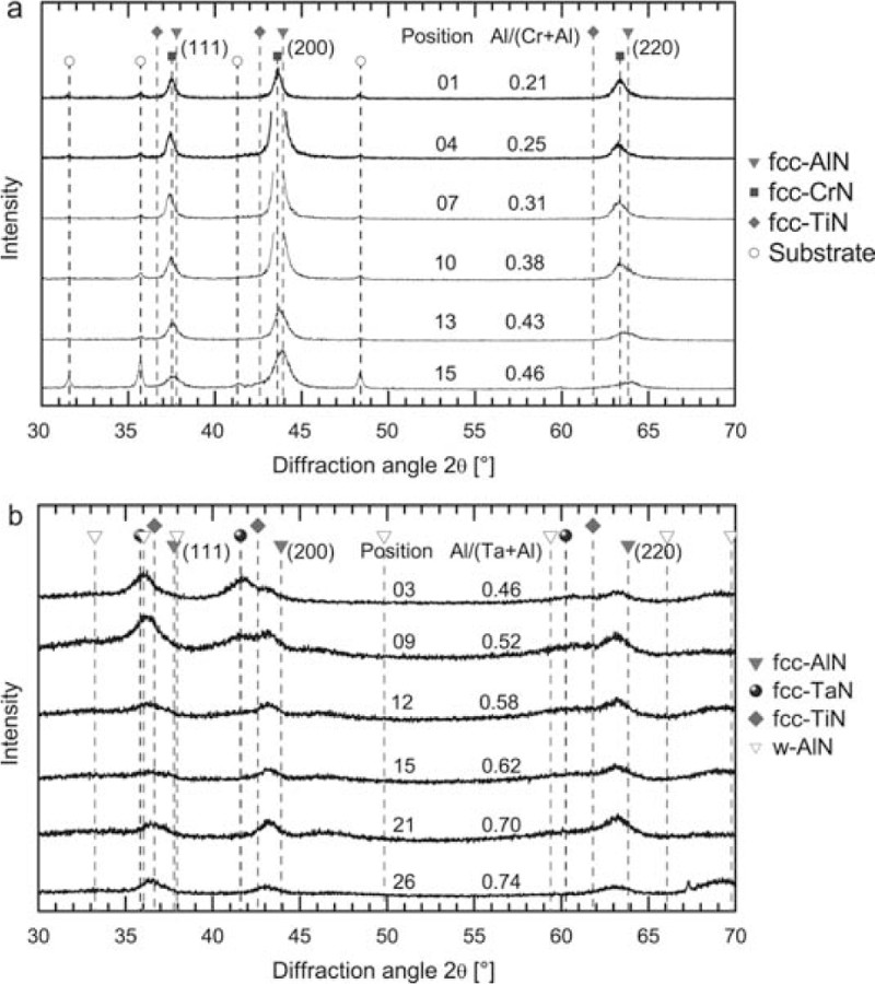
X-ray diffractograms of a Cr1 − xAlxN bilayers deposited on SNUN cemented carbide inserts (grazing incidence) and b Ta1 − xAlxN bilayers deposited on Si substrates (Bragg–Brentano geometry)
In Fig. 3b, the diffractograms detected in Bragg–Brentano geometry of the Ta1 − xAlxN bilayers deposited on Si substrates at different positions and the corresponding Al/(Ta+Al) ratios are shown. The standard peak positions for the fcc AlN, TiN, TaN and w AlN phase 16 are also given. Even for the coatings with the highest Al contents, no distinct w AlN peaks are discernible, implying that the coatings still predominantly consist of a fcc Ta1 − xAlxN solid solution. This suggests that the maximum solubility of Al in the metastable fcc Ta1 − xAlxN phase might be higher than in Ti1 − xAlxN or Cr1 − xAlxN, where the solubility limit is x ∼0·7.1,14,17 For lower Al contents, the peaks of the TiAlN base layer and the Ta1 − xAlxN top layer can be distinguished. With increasing Al content, the Ta1 − xAlxN peak intensity decreases and is shifted towards higher diffraction angles until only a shoulder on the left hand side of the TiAlN (200) and (220) peaks is visible. The Ta1 − xAlxN (111) peak is more pronounced and still visible at high Al contents, with a distinct TiAlN shoulder on the right hand side. The shift to higher diffraction angles can, equally to the Cr1 − xAlxN, be attributed to a decreasing lattice parameter of the Ta1 − xAlxN phase with increasing Al content, since the smaller Al substitutes for Ta in the fcc TaN lattice.
Hardness
The hardness of the Cr1 − xAlxN coatings varies in the range of 16–25 GPa, while for the Ta1 − xAlxN coatings, it lies between 17 and 21 GPa, as shown in Fig. 4. The hardness of Cr1 − xAlxN increases with increasing Al content due to increasing solution hardening, until reaching a maximum at Al/(Cr+Al) ∼0·37 (i.e. sample position 18). The increasing hardness with increasing Al content is in good agreement with literature.1,2 The pronounced decrease in hardness for Al/(Cr+Al) >0·43 (i.e. above sample position 24) can on the one hand be related to an intensified substrate ion/neutral flux ratio in front of the Al target segment, originating from a more pronounced scattering of the lighter Al compared to the heavier Cr atoms, 11 resulting in a higher coating defect level. In addition, a boundary effect can be expected resulting in further reduction of the atom flux to the substrates, since these samples are mounted near the edge of the target. 11 For the Ta1 − xAlxN bilayers, no hardness increase with rising Al content could be detected. After maintaining a hardness level of ∼20 GPa up to substrate position 18 [corresponding to Al/(Ta+Al) ∼0·66], a slight decrease similar to Cr1 − xAlxN at higher Al contents is observed.
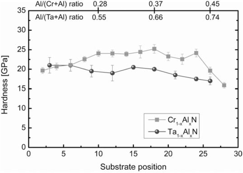
Hardness of Cr1 − xAlxN and Ta1 − xAlxN bilayers depending on position of Si substrates
Tribological properties
The development of the coefficient of friction (COF) as a function of the sliding distance at RT as well as the shape of the wear track for a Cr1 − xAlxN bilayer rich in Cr [Al/(Cr+Al) ∼0·26] are shown in Fig. 5a and b. After a short running in period, a steady state COF of ∼0·36 was obtained resulting in a low wear rate of 3·2x10− 16 m3 Nm− 1. With increasing Al content, the RT steady state COF increases, as shown in Fig. 6a. This is in good agreement with literature and most probably due to increasing coating roughness.2,11 According to Fig. 6b, no distinct dependence of the wear rate on the Al/(Cr+Al) atomic ratio can be observed. However, it should be noted, that the coatings grown on the 30 mm diameter cemented carbide discs are characterised by an inherent lateral gradient in chemical composition, thus covering a broader compositional range than the SNUN inserts used for energy dispersive X-ray spectrocopy measurements.
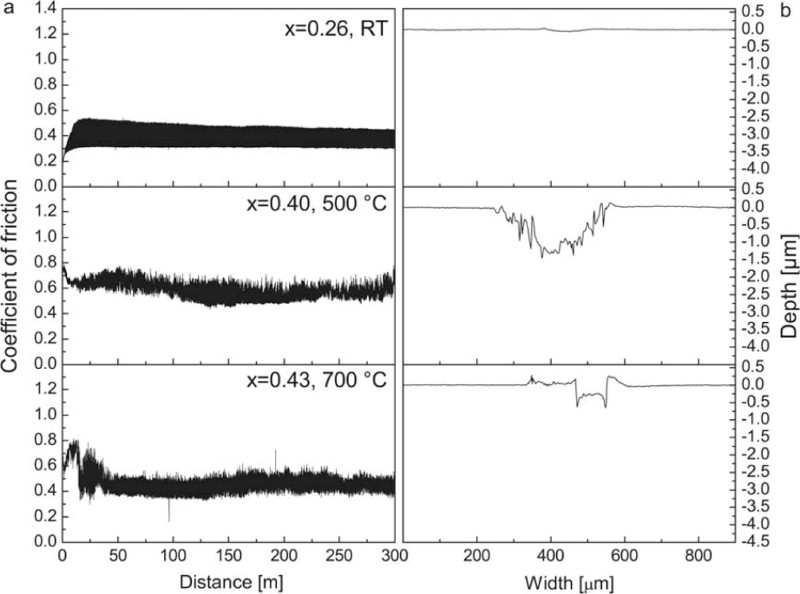
Representative diagrams for a friction curve and b wear track profile of Cr1 − xAlxN bilayer obtained at RT, 500°C and 700°C
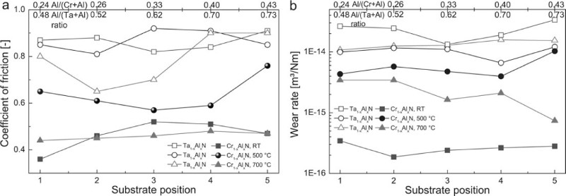
a coefficient of friction and b wear rate of Cr1 − xAlxN and Ta1 − xAlxN bilayers as function of substrate position
Exemplarily, the friction coefficient as a function of the sliding distance and the corresponding wear track profile for Al/(Cr+Al) ∼0·40 tested at 500°C are shown in Fig. 5a and b. Compared to RT, at 500°C, a higher steady state COF of ∼0·59 was obtained, which can be related to the formation of a reaction or transfer layer at this high temperature and, consequently, to tribochemical or adhesive wear. The wear track depth is in the range of the Cr1 − xAlxN layer thickness (Fig. 5b), resulting in a significantly higher wear rate than at RT of 4·0x10− 15 m3 Nm− 1. The evolution of the COF and the wear rate with increasing Al content are shown in Fig. 6a and b. The COF values for the coatings with the lowest and the highest Al content in the Cr1 − xAlxN layer are increased compared to the other COF values. This can be attributed to complete failure of the Cr1 − xAlxN top layer of the coating with the lowest Al content [Al/(Cr+Al) ∼0·24] after a sliding distance of only ∼150 m. In case of the coating with the highest Al content [(Al/(Cr+Al) ∼0·43], not only the Cr1 − xAlxN layer fails but also the TiAlN base layer. This is clearly visible in the respective friction curves and wear track profiles (not shown here). In Fig. 6a, only the COF values before failure of the Cr1 − xAlxN layers were considered. No distinct dependence of the wear rate on the Al/(Cr+Al) atomic ratio can be observed (Fig. 6b), only the coating with the highest Al content [(Al/(Cr+Al) ∼0·43] exhibits a higher wear rate, which can be related to the failure of the whole bilayer system.
The friction curve and wear track profile for the Al/(Cr+Al) ∼0·43 sample tested at 700°C are shown in Fig. 5a and b. At 700°C, the COF values are significantly lower than at 500°C, without distinct influence of the Al content (Fig. 6a). In contrast, the increasing Al/(Cr+Al) atomic ratio has a pronounced effect on the wear rate (Fig. 6b), which considerably decreases from 3·4x10− 15 m3 Nm− 1 at Al/(Cr+Al) ∼0·24 to 7·4x10− 16 m3 Nm− 1 at Al/(Cr+Al) ∼0·43. This means that for the shallow wear tracks obtained at 700°C (Fig. 5a), a high Al content is necessary. Summarising, it can be concluded that the Al content within the composition range investigated here does not significantly affect the tribological performance of Cr1 − xAlxN at RT and 500°C since the dominating abrasive wear is essentially governed by the coating hardness. In contrast, at 700°C, tribochemical wear leads to formation of an Al2O3 rich protective oxide scale, where a sufficient Al content is needed.18,19 The sputter deposited Cr1 − xAlxN bilayers investigated within this work result for all tested temperatures in significantly lower friction compared to arc evaporated coatings 20 , accompanied by a high resistance to abrasive wear, when assuming that at RT ploughing of surface asperities is dominating. 11 This is related to the lower surface roughness of sputtered coatings with respect to arc evaporated coatings, which are characterised by a high number of droplets resulting from the deposition process. 21
Compared to the Cr1 − xAlxN bilayers, significantly higher steady state COF values have been obtained for the Ta1 − xAlxN bilayers at RT (Fig. 6a), which is most probably related to the failure of the whole bilayer system. In Fig. 7a and b, representative examples for the COF as a function of the sliding distance and the wear track profile for a Ta1 − xAlxN bilayer [Al/(Ta+Al) ∼0·52] are shown. In contrast to the Cr1 − xAlxN bilayer, the COF values are in the same range at RT and at 500°C (Fig. 6a). Examplarily, the friction curve and the wear track profile for a Ta1 − xAlxN bilayer [Al/(Ta+Al) ∼0·52] tested at 500°C are shown in Fig. 7a and b. The wear track profile is shallow, but considering the different x scale, it is very broad, resulting in a wear rate comparable to the ones at RT (Fig. 6b). The development of the COF as a function of the sliding distance and the wear track profile for the Ta1 − xAlxN bilayer [Al/(Ta+Al) ∼0·52] tested at 700°C are shown in Fig. 7a and b. Compared to RT and 500°C, a lower COF of ∼0·65 was obtained, but an increased tendency to negative (i.e. predominantly abrasive wear with a wear rate of 1·3x10− 14 m3 Nm− 1) and positive wear (i.e. tribochemical wear and material transfer, Fig. 7b) was observed. Summarising, for the Ta1 − xAlxN bilayer, no distinct dependence of the tribological behaviour on the Al content can be observed (Fig. 6a and b), which is most probably attributed to the fact that the Al content is for all substrate positions already quite high (Fig. 2c).
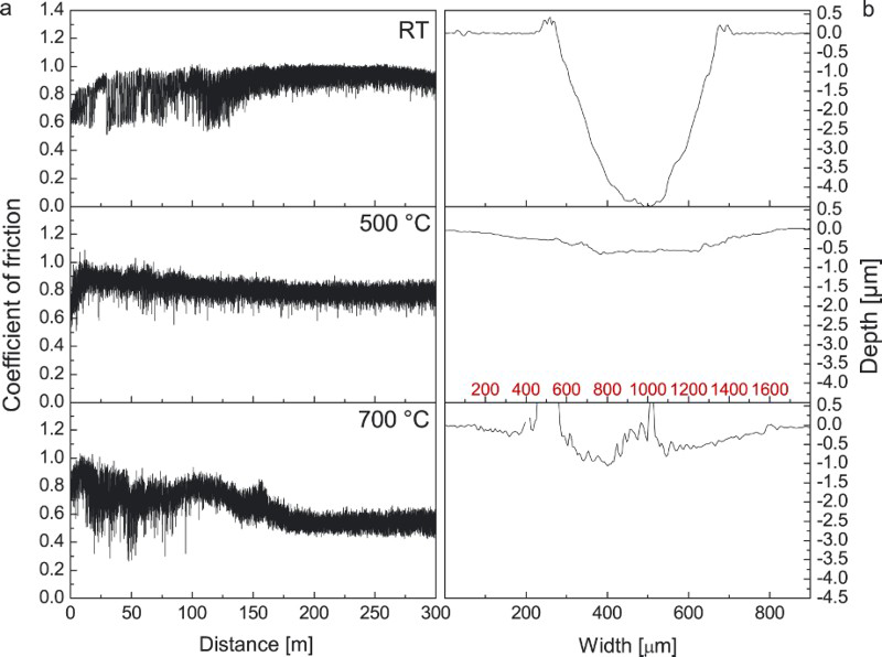
Representative diagrams for a friction curve and b wear track profile obtained for Ta1 − xAlxN bilayer with x ∼0.52 at RT, 500°C (please note the different x scale) and 700°C
Conclusions
A combinatorial deposition approach using triangular shaped segmented sputter targets has been successfully applied to deposit ternary transition metal aluminium nitride coatings on TiAlN base layers on an industrial scale. Owing to the position of the substrates relative to the target segments, a variation of the Al/(Cr+Al) atomic ratio in the range of 0·21 to 0·46 was observed for Cr1 − xAlxN bilayers, exhibiting a single phase cubic structure. For the Ta1 − xAlxN bilayers, Al/(Ta+Al) atomic ratios in the range of 0·45 and 0·76 could be obtained, where even the high Al containing coatings consisted predominantly of the cubic structure. The Cr1 − xAlxN and Ta1 − xAlxN bilayers yielded hardness values in the range of 16–25 and 17–21 GPa respectively. In general, the Cr1 − xAlxN bilayer demonstrated a better tribological performance compared to the Ta1 − xAlxN bilayer. Especially at RT and 700°C, the Cr1 − xAlxN bilayer showed superior tribological properties, provided that the Al content is sufficiently high. Finally, it can be concluded that the deposition of multicomponent coatings using the investigated segmented target approach has a strong potential to analyse their structure–property evolution under industrial scale sputter deposition conditions over a broad composition range in one single deposition run.
Acknowledgements
This work was carried out within the Research Studio Austria energy drive (grant number 832040), with financial support from the Österreichische Forschungsförderungsgesellschaft and the Bundesministerium für Wirtschaft, Familie und Jugend. Dr S. Gangopadhyay is grateful to the Department of Science and Technology, Government of India, for awarding the BOYSCAST Fellowship (file no. SR/BY/E-02/10).