
Abstract
In this work, American Iron and Steel Institute (AISI) O1 steel was pack borided in the temperature range of 1123–1273 K for treatment times between 2 and 8 hours. A kinetic model was proposed for estimating the boron diffusion coefficients through the Fe2B layers. As a result, the boron activation energy for the AISI O1 steel was estimated as 197·2 kJ mol− 1. This value of energy was compared to the literature data. In addtion, to extend the validity of the present model, two additional boriding conditions were done. The Fe2B layers grown on AISI O1 steel were characterised by use of the following experimental techniques: scanning electron microscopy, X-ray diffraction analysis and Daimler-Benz Rockwell-C indentation technique. Finally, the scratch and pin on disc tests for wear resistance were respectively performed using an LG Motion Ltd and a CSM tribometer under dry sliding conditions.
Introduction
Boriding is a thermochemical diffusion process in which the boron atoms are extracted from boron containing media and deposited onto the sample surface. 1 It has been applied to a wide range of materials, including ferrous, non-ferrous and some super alloys. The boriding process results in some important improvements in surface properties, such as high hardness, resistance against wear and corrosion.2–4 The diffusion of atomic boron into the material substrate results in the formation of a wear resistant iron boride layer on the surface of steel parts. The boride layer is composed of either a single phase layer of Fe2 B or a double phase layer (Fe2B+ FeB) according to the Fe–B phase diagram. The monolayer configuration (Fe2B) is desirable to the double phase layer since the FeB phase is more brittle and harder than Fe2B and has a coefficient of thermal expansion superior than that of Fe2B. This situation can cause cracks when a double phase layer is formed. In practice, there are many boriding methods to form boride layers on different substrates, such as gas boriding,5,6 liquid boriding, 7 powder or paste boriding,8,9 and laser boriding. 10 The most frequently used method is pack boriding because of its technical advantages and cost effectiveness.11,12 In a kinetic point of view, several mathematical models concerning the growth kinetics of Fe2B layers on different substrates9,13–26 were suggested in the literature. These approaches are considered as a tool to select the adequate boride layers thicknesses for practical applications. Until now, no studies were reported in the literature about the boriding kinetics of AISI O1 steel.
The AISI O1 steel is a high quality non-distorting cold work tool steel. It is suitable for a wide variety of cold work applications. It has a certain resístance against abrasion with a good machinability and sufficient toughness for normal tool and die applications. The pack boriding treatment was used to improve the tribological properties and extend the lifetime of the workpieces made of AISI O1 steel.
The aim of this work was to investigate the growth kinetics and mechanical behaviour of the pack borided AISI O1 steel. A diffusion model was proposed to determine the boron diffusion coefficients in the Fe2B layer at the surface of AISI O1 steel considering a constant boride incubation time. As a result, the boron activation energy for the AISI O1 steel was estimated using this diffusion model basing on our experimental results. For metallurgical investigation, scanning electron microscopy (SEM) and X-ray diffraction (XRD) analysis were used to characterise the pack borided AISI O1 steel. For mechanical characterisations, the Daimler-Benz Rockwell-C indentation technique was used to characterise the cohesion of boride layer on the surface of AISI O1 steel. In addition, the sample borided at 1123 K with 4 hours of exposure time was tested in an LG Motion Ltd (scratch) and a CSM tribometer (pin on disc) in ambient air at room temperature. Friction coefficient and wear behaviour were finally compared with the unborided AISI O1 steel.
Diffusion model
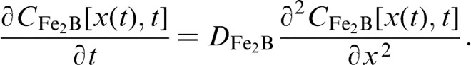
Mass balance equation
The model takes into account the growth of Fe2B layer on a saturated substrate with boron atoms, as shown in Fig. 1. The f(x,t) function illustrates the boron distribution in the ferritic matrix before the nucleation of Fe2B phase.
 corresponds to the incubation time required to form the Fe2B phase when the matrix reaches a saturation state with boron atoms.
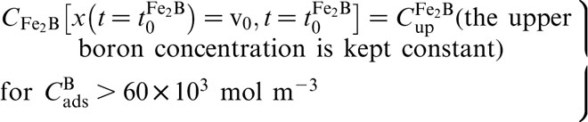
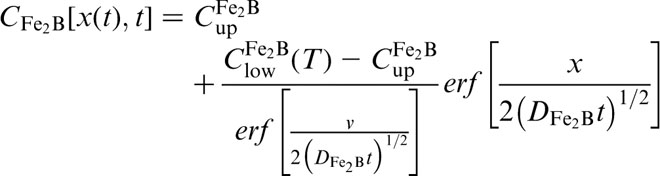
 represents the upper limit of boron content in Fe2B ( = 60 × 103 mol m− 3),
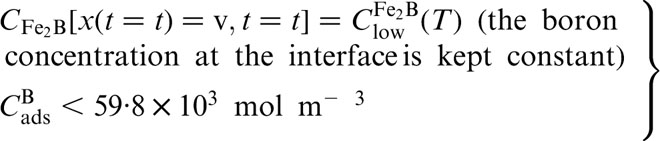
 is the lower limit of boron content in Fe2B with
 = ( − 0·0004T+60·373) × 103 mol m− 3 and the point x(t = t) = v refers to the Fe2B layer thickness.9,24–26 The term
 is the effective adsorbed boron concentration during the boriding process.
27
Likewise, the homogeneity of the distribution of boron inside the Fe2B layer can be described by the parameter
is the effective adsorbed boron concentration during the boriding process.
27
Likewise, the homogeneity of the distribution of boron inside the Fe2B layer can be described by the parameter
 .
.
 is the miscibility gap, and C0 is the boron solubility in the matrix. This diffusion zone in the substrate underneath the compound layer can be ignored by setting (
 mol m− 3)28,29 due to the lower solubility of boron in the matrix. The assumptions taken into account during the formulation of the diffusion model can be found elsewhere.
9
mol m− 3)28,29 due to the lower solubility of boron in the matrix. The assumptions taken into account during the formulation of the diffusion model can be found elsewhere.
9
Schematic boron concentration profile through Fe2B layer
The initial and boundary conditions for the diffusion problem are represented as

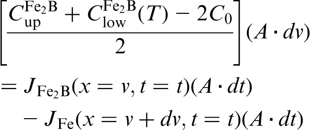

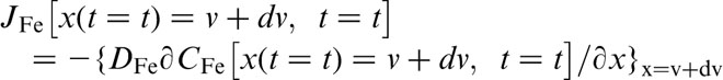
Thus, equation (4) can be written as
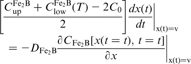
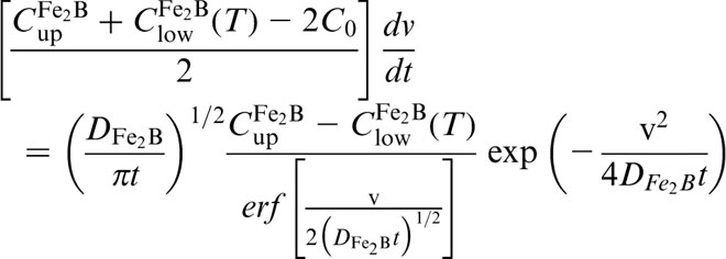
By substituting the derivative of the parabolic growth law (
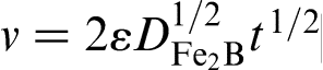 ) with respect to time t into equation (10), equation (11) is deduced as
 ,
,
 and
and
 do not depend significantly on temperature (in the considered temperature range).
26
do not depend significantly on temperature (in the considered temperature range).
26
Experimental procedure
Boriding process
The material to be pack borided is the AISI O1 steel. It has a nominal chemical composition of 0·85–1·00%C, 0·30–0·50%Si, 1·00–1·40%Mn, 0·40–0·60%Cr, 0·40–0·60%W, 0·10–0·30%V, 0·030%P and 0·030%S. The samples are cubic shaped of dimension 10 × 10 × 10 mm. Prior to the boriding process, the samples were polished, ultrasonically cleaned in an alcohol solution and deionised water for 15 min at room temperature and then dried and stored under clean room conditions. The samples were embedded in a closed cylindrical case (AISI 304L), containing a fresh Durborid powder mixture. The boriding agent, with an average particle size of 30 μm, was composed of an active source of boron (B4C), an inert filler (SiC) and an activator (KBF4). The boriding process was carried out in the temperature range of 1123–1273 K for a variable time (2, 4, 6 and 8 hours). Once the treatment was finished, the container was removed from the furnace and slowly cooled to room temperature.
Experimental techniques
The borided and etched samples were cross-sectioned, for microstructural investigations, to be observed by SEM (JEOL JSM 6300). For a kinetic study, the boride layer thickness was automatically measured with the aid of an MSQ PLUS software. To ensure the reproducibility of the measured layers, 50 measurements were taken from different sections of the borided samples to estimate the Fe2B layer thickness; defined as an average value of the long boride teeth.31–32 The presence of different borides formed at the surface of AISI O1 steel was determined by means of an XRD equipment (Equinox 2000) using Co Kα radiation at λ = 0·179 nm. The Daimler-Benz Rockwell-C technique was performed to attain qualitative information on the cohesive strength of the boride layers to the substrate. The well known Rockwell-C indentation test is prescribed by the VDI 3198 norm as a destructive quality test of coated compounds.33–35 A load of 1471 N was applied to cause coating damage adjacent to the boundary of the indentation. Three indentations were made for each borided sample to assess the cohesion test. The indentation craters on the surfaces of samples were observed by SEM (JEOL JSM 6300). The pin on disc wear tests were achieved at ambient conditions without lubrication. Before the test, the samples were cleaned with acetone in order to remove contaminants from the surface. The tested samples had a disc shape with a diameter of 25·4 mm and a thickness of 10 mm. Tribological tests were performed with a diamond made indenter with a 10 mm diameter hemispheric and wear test machine (CSM tribometer (pin on disc)) at room temperature and a relative humidity of 40%. All tests were conducted for a total sliding distance of 500 m with a sliding speed of 0·08 m s− 1, and the covered radial distance was 14 mm under a normal load of 5 N. The pin on disc test was achieved on a Revetest device equipped with an acoustic emission sensor that measures the loads in situ when damage occurs and another that permits direct recording of the tangential force that gives the instantaneous friction coefficient. Before the scratch wear tests, the samples with a rectangular shape of dimensions 12 × 7 × 7 mm were cleaned with acetone in order to remove the contaminants from the surface. The test consists of scratching the sample surface by using an LG Motion Ltd (scratch) with a single pass under increasing normal load at a rate of 10 N mm− 1 of covered distance. The scratch wear tests were realised at ambient conditions without lubrication.
Experimental results and discussions
Microscopical observations of boride layers
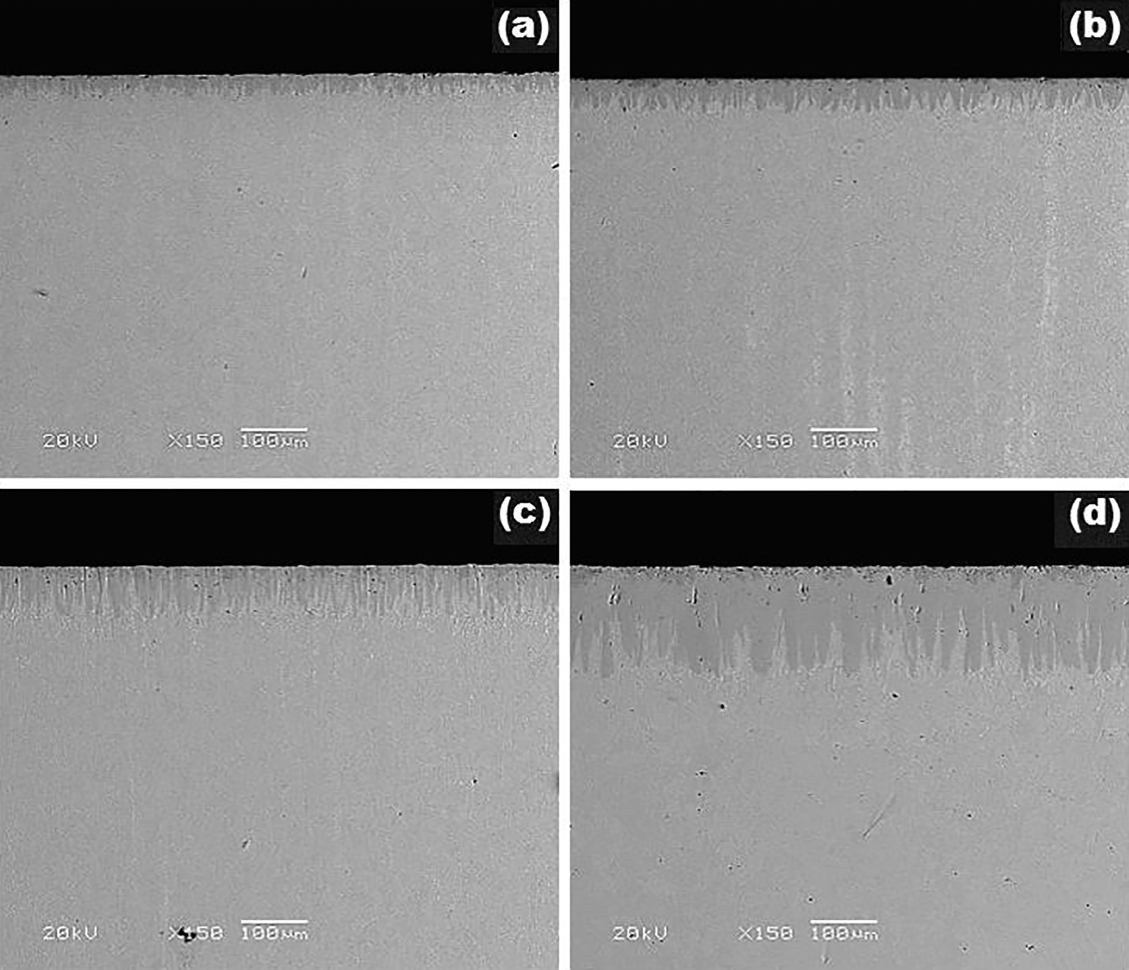
Figure 2 shows the cross-sections of boride layers formed on the surfaces of AISI O1 steel at different temperatures and for 6 hours of exposure time. The resultant microstructure of Fe2B layers looks very dense, compact and homogenous, with reduced sawtooth morphology. This peculiar morphology is ascribed to the presence of carbon and alloying elements in AISI O1 steel. In fact, the carbon content in the steel influences the nature of (boride layer/substrate) interface. Generally, with an increase in the steel's carbon content, there is a tendency to reduce the formation of a jagged interface between the steel substrate and the boride layer. In addition, the alloying elements present in the steel tend to concentrate in the tips of boride layers, reducing the boron flux in this zone.
Images (SEM) of cross-sections of borided AISI O1 steel during 6 hours of treatment at different boriding temperatures: a 1123 K; b 1173 K; c 1223 K; d 1273 K
X-ray diffraction analysis
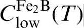
Figure 3 shows the XRD patterns obtained at the surfaces of borided AISI O1 steel at 1273 K for 6 and 8 hours of treatment. The formation of Fe2B layer at the surface of AISI O1 steel is confirmed by XRD analysis. It is noted that the diffractions peaks are different in intensity and depend on the crystallographic orientations of Fe2B crystals. In a kinetic point of view, the Fe2B crystals begin to nucleate when the matrix reaches the saturation level by boron atoms. Furthermore, the boron solubility in iron is very low and strongly dependent on irregularities in the crystal lattice and therefore also on the purity of the same metal. Afterwards, the boride layer becomes compact and continuous with a prolonged treatment time. The crystallographic direction [001] is the easiest path for the boron diffusion in the Fe2B phase because of the tendency of boride crystals to grow along a direction of minimum resistance. For this reason, the growth of Fe2B layer is of a highly anisotropic nature. 36
X-ray diffraction patterns obtained at surfaces of borided AISI O1 steel at 1273 K for 6 and 8 hours of treatment
Rockwell-C cohesion test
An indenter hardness tester was used to assess the Daimler-Benz Rockwell-C cohesion as a destructive quality test for the examined layers; it was employed for the determination of cohesion. A conical diamond indenter penetrated into the surface of an investigated layer, thus inducing massive plastic deformation to the substrate and fracture of the boride layer. The damage to the boride layer was compared with the cohesion strength quality maps HF1–HF6. In general, the cohesion strengths HF1 to HF4 are defined as sufficient cohesion, whereas HF5 and HF6 represent insufficient cohesion. 33 Fig. 4 shows the SEM images of the indentation craters after the VDI cohesion test on the surfaces of AISI O1 steel borided at 1123 K during 2 and 5 hours. The indentation craters obtained on the surface of the pack borided AISI O1 steel revealed that they were radial cracks at their perimeter. However, a small quantity of spots with flaking resulting from delamination was visible, and the cohesion strength quality of this boride layer is related to the HF3 standard.
Images (SEM) showing indentations of VDI cohesion test on surfaces of AISI O1 steel borided at 1123 K for variable treatment times: a 2 hours; b 8 hours
Tribological characterisation
The pin on disc tests were carried out in dry sliding conditions using a CSM tribometer. This machine is used to determine the magnitude of friction coefficient and wear as two surfaces rub together. In one measurement method, a pin or a sphere is loaded onto the test sample with a precisely known force. The pin is mounted on a stiff lever designed as a frictionless force transducer. The friction coefficient is determined during the test by measuring the deflection of the elastic arm. A diamond made indenter with a 10 mm diameter hemispheric, commonly employed, was used to slide against the surface of the borided AISI O1 steel. Figure 5 shows the variation in friction coefficient of the borided and unborided surfaces under dry sliding conditions against a diamond made indenter. Figure 5 points out that the borided sample exhibited a friction coefficient lower than that of the unborided substrate. The average friction coefficient, for the borided sample at 1123 K for 4 hours, ranged from 0·398 to 0·375, while the average friction coefficient was between 0·637 and 0·612 for the unborided substrate. These results agree with those obtained in other works.37–39 Figs. 6 gives the SEM images of the unborided and borided surfaces obtained at 1123 K with exposure time of 4 hours respectively. A defined wear scar is produced, which has a width of approximately 0·902 and 0·610 mm respectively. In Fig. 6a, the wear debris and scratching lines are observed, whereas common wear mechanisms, like plastic deformation, are viewed on the unborided surface. Figure 6b shows the wear scar formed on the borided surface, where some pits and scratching lines are observed. The scratch tests were carried out in dry sliding conditions using an LG Motion Ltd. In this technique, the tip material (commonly diamond or hard metal (WC)) is drawn across the borided surface under constant, incremental or progressive load. Figures 7 displays the SEM images of the borided surfaces of AISI O1 steel at 1123 and 1273 K with exposure time of 4 hours respectively. It is noticed that the cracks propagate in depth along the scratch trails. They have either a curvilinear form (see Fig. 7b) or a mosaic (see Fig. 7d). According to the literature, this type of cracks is characteristic of a Hertzian fracture on brittle solids when a blunted indenter is used. These cracks propagate in depth in a semiconical shape and start at flaws near the contact surface where high tension stresses develop.40,41 There was not a case of cohesive scaling at the (Fe2B /substrate) interface was observed. This was expected since it is well established that the coatings achieved at high temperature present a good cohesion due to the interdiffusion phenomenon ensuring the continuity of metallic interface.

Variation of friction coefficient of diamond indenter during sliding against borided surface of AISI O1 steel at 1123 K during 4 hours and unborided substrate
Images (SEM) of wear scar on surfaces of AISI O1 steel: a unborided surface and b borided surface at 1123 K for 4 hours
Images (SEM) of wear scar on surfaces of AISI O1 steel for two boriding conditions: a 1123 K for 4 hours; b 1123 K for 4 hours; c 1273 K for 4 hours; d 1273 K for 4 hours
Estimation of boron activation energy
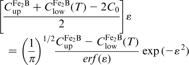
The growth kinetics of Fe2B layers formed on the AISI O1 steel was used to estimate the boron diffusion coefficient in the Fe2B layers by applying the suggested diffusion model. The determination of ε parameter by solving equation (11) is required to deduce the value of boron diffusion coefficient in the Fe2B layer at each boriding temperature. Figure 8 gives the time dependence of the squared value of the Fe2B layer thickness for increasing temperatures. The slopes of the straight lines, displayed in Fig. 8, give the values of growth constants ( = 4ε2 DFe2B).
Square of boride layer thickness versus boriding time at different temperatures
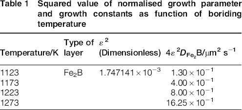
Table 1 provides the values of growth constants ( = 4ε2
DFe2B) along with the squared normalised value of ε determined from equation (11). To estimate the boron activation energy for the AISI O1 steel, it is necessary to plot lnDFe2B as a function of reciprocal boriding temperature following the Arrhenius equation (see Fig. 9). So, the time dependence of boron diffusion coefficient in the Fe2B layer was obtained from a linear fitting as follows

Squared value of normalised growth parameter and growth constants as function of boriding temperature
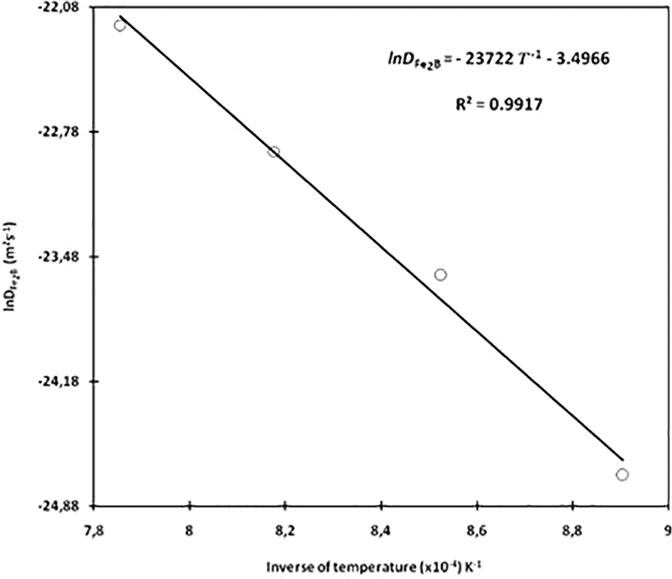
Temperature dependence of boron diffusion coefficient in Fe2B layer
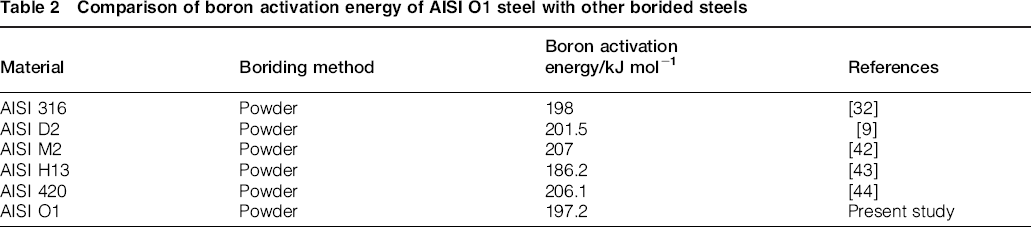
The growth kinetics of Fe2B layers proposed by the diffusion model was also verified by estimating the Fe2B layers thicknesses for additional boriding conditions. Figures 10 shows the SEM images of the cross-sections of the samples borided at 1148 and 1248 K for 1 and 4 hours, respectively. Table 2 compares the value of boron activation energy for AISI O1 steel with the values found in the literature for some borided steels.9,32,42–44 It is concluded that the reported values of boron activation energy depended on various factors, such as the nature of boriding agent, the chemical composition of base steel and the kinetic approach used. However, some reported values of boron activation energies in the literature for borided steels are very different. For indication, the value of boron activation energy obtained by Ipek et al. 45 on the pack borided AISI 51100 that contains 0·9 % C was 106 kJ mol− 1. This value of energy is found to be lower when compared to the values listed in Table 2.
Images (SEM) of boride layers formed at surface of AISI O1 steel for different boriding conditions: a 1148 K for 1 hour; b 1148 K for 4 hours; c 1248 K for 1 hour; d 1248 K for 4 hours
Comparison of boron activation energy of AISI O1 steel with other borided steels
This obtained value of boron activation energy for the AISI 51100 steel 45 (with the presence of alloying elements) is incompatible with the data estimated for the borided Armco iron.19,25,46 A high value of boron activation energy is obtained for the alloy steel with increasing alloying elements. 47 As a consequence, the boride layer thickness is also reduced because of the effect of alloying elements.
The value of boron activation energy found in this work (i.e. 197·2 kJ mol− 1) was interpreted for the borided AISI O1 steel as the amount of energy for the movement of boron atoms in the easiest path direction [001] along the boride layer that minimises the growth stresses. This value of energy can also be interpreted as the required barrier to allow boron diffusion inside the metal substrate. Thus, the diffusion phenomenon of boron atoms can occur along the grain boundaries and also in volume to form the Fe2B layer on the steel's substrate.
48
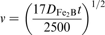
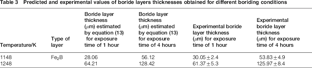
From equation (13), the boride layers thicknesses are described as follows
Predicted and experimental values of boride layers thicknesses obtained for different boriding conditions
Conclusion
In this work, the growth kinetics and some mechanical properties of Fe2B layers formed at the surface of AISI O1 steel were investigated in the temperature range of 1123–1273 K for a variable exposure time between 2 and 8 hours. A simple kinetic model was proposed to evaluate the boron diffusion coefficient in Fe2B. As a result, the value of boron activation energy was estimated as 197·2 kJ mol− 1 for the AISI O1 steel. Validity of the present model was verified by comparing the experimental Fe2B layer thicknesses with the predicted values for the samples borided at 1148 and 1248 K for 1 and 4 hours respectively. A good agreement was then observed between the predicted values of Fe2B layers thickness and those obtained experimentally. The interfacial adherence of the boride layers on the AISI O1 steel (obtained at 1123 K during 2 and 4 hours), by the Daimler-Benz Rockwell-C indentation technique, was found to be related to HF3 category according to VDI 3198 norm. The average friction coefficient for the borided sample was between 0·398 and 0·375 while the corresponding value for the unborided substrate ranged from 0·637 to 0·612. The characteristic wear mechanism for the unborided surface was plastic deformation; debris and scratching lines are observed. For the borided surface of AISI O1 steel, some pits and scratching lines are noticed.
Acknowledgements
The work described in this paper was supported by a grant of CONACyT and PROMEP México. Also, the authors want to thank Ing. Martín Ortiz Granillo, who is in charge as Director of the Escuela Superior de Ciudad Sahagún, which belongs to the Universidad Autónoma del Estado de Hidalgo, México, for all the facilities to accomplish this research work.