
Abstract
The paper deals with the problem of coating production on internal pipe surfaces by the cold spraying. It reports on a new assembly design with a radial supersonic nozzle that greatly facilitates the application of aluminium, copper and nickel coatings onto internal pipe surfaces. Visualisation and Pitot tube measurements of the airflow produced by the nozzle assembly assist to predict the range of internal pipe diameters, in which the pipes could be successfully coated from the inside using the designed instrument. The velocity of aluminium particles has been measured at the exit from the radial nozzle and calculated the particle velocities under the actual cold spray conditions. Finally, the mass and energy consumption characteristics of the process and the deposition efficiencies achievable under typical experimental conditions have been calculated. Those calculations have allowed us to evaluate the cost of potential introduction of the cold spray process into pipe production.
Introduction
Cold spraying is a rapidly evolving method for coating production using powders. Its basic feature is as follows: metal particles sized usually < 100–200 μm are accelerated by a working gas inside a supersonic nozzle, impact onto a substrate surface and stuck to it to form a coating. Relative simplicity of practical implementation of the cold spray process allows the development of new technologies and approaches for coating production in very different cases. Engineering solutions using optimal selection of the working gas, 1 the size and shape of powders, 2 a proper deposition strategy (number of passes, scanning velocity, etc.), 3 spray angle, 4 powder heating, 5 optimal geometry of masks, 6 optimal selection of sublayers, 7 deposition of submicrometric powders in vacuum, 8 and also application of micronozzles (down to 50 μm in diameter) suitable for deposition of nanopowders (including alumina) 9 have been proposed. In addition, advances in cold spray metallisation of glass and silicon, 10 different plastics,11–15 and deposition of plastic powders16,17 are remarkable. All those developments show that the applications of the cold spraying method are perfectly versatile. Production of various (corrosion resistant, heat conducting, refractory, 18 etc.) coatings on the internal surfaces of cylindrical articles (pipes, etc.) is also an important problem. Two possible approaches to this problem are well known. One approach implies using a single nozzle with pipe rotation,19–21 and the other approach using an annular nozzles without pipe rotation.22–24 However, in the devices proposed for implementation of second approach,22–24 the particles acquire a high velocity, and then, at the end of their acceleration path, they turn around through an angle of ∼90 ± 5°. Under such conditions, the particles inevitably impinge onto the wall of the turning channel, with their velocities decreasing in magnitude. Moreover, the impacts of the high velocity particles onto the channel wall lead to either erosion or deposition depending on the particular particle and wall materials used as well as on the temperatures, impact angles, etc. Both processes change the channel shape and, therefore, particle parameters and conditions of the deposition process. A better strategy here would consist in letting the particles turn their trajectory at a place where the particles have low velocities.
An assembly with a radial supersonic nozzle in which particles turn their trajectory at the beginning of their acceleration path enables avoiding the above mentioned drawbacks. Here, the radial supersonic nozzle (hereinafter, radial nozzle) is formed by two co-axial discs spaced apart by some distance. In this assembly, the working gas flow seeded with particles fed from the axial zone spreads radially in the gap between the two discs at supersonic velocities, thus imparting the particles with high velocities.
However, today the behaviour of two-phase flows in radial nozzles remains a scantily understood matter. In the present study, we therefore investigated both the gas and particle motion, and the possibility of production of continuous coatings on the internal surfaces of cylindrical pipes by the cold spraying method using a radial nozzle. First, we have attempted to identify the range of internal pipe diameters for pipes that could be coated from the inside using the designed nozzle assembly. Second, the required consumption of mass and energy has been evaluated. Such estimates are necessary for evaluating the potential the proposed approach has in the pipe production industry. A detailed examination of the properties of the cold sprayed coatings was beyond the scope of the present preliminary study.
Experimental
Figure 1 shows a diagram of the cold spray process implemented with the help of a radial nozzle with indicated basic geometric dimensions. A working gas (air) at a preset pressure and temperature comes from a gas heater into the nozzle assembly body (1) and, then, it enters prechamber 6 through perforations 4. A powder (admixed to a carrier gas) comes into the prechamber from a powder feeder through radial perforations 5. Before reaching the nozzle throat of diameter dcr, the working gas loaded with the powder particles turns its motion direction, accelerates in the supersonic part of radial nozzle (between the throat at dcr and the exit at dex section) and produces a coating 11, while the nozzle assembly moves along the pipe axis at an appropriate velocity vs (Fig. 1)
Diagram of internal coating deposition process using radial nozzle assembly: 1, assembly body; 2, working gas inlet; 3, powder/carrier gas inlet; 4, perforations for blowing working gas into prechamber; 5, perforations for injection of powder into prechamber; 6, prechamber; 7, radial nozzle; 8, point for measuring prechamber pressure; 9, point for measuring nozzle exit pressure; 10, pipe; 11, coating
Two radial nozzle assemblies were fabricated (see Fig. 2). The first assembly, whose exit diameter was 72 mm and the throat diameter was 18 mm, will be referred to below as the 72 mm radial nozzle assembly, and the second assembly, whose exit diameter was 40 mm and the throat diameter was 10 mm, will be referred as the 40 mm radial nozzle assembly. Both assemblies were designed to allow their operation at a variable separation (0·5–2 mm) between the nozzle walls δn (hereinafter, nozzle width).
Photos of radial nozzle assemblies; upper part of figure: 72 mm radial nozzle assembly (dcr = 18 mm); lower part of figure: 40 mm radial nozzle assembly (dcr = 10 mm)
For introducing a radial nozzle assembly into the pipe, a rod was used on which the assembly was rigidly mounted. The rod had internal channels through which the nozzle was fed with the working gas and with the powder/carrier gas mixture. The length of the rod defined the maximum pipe length that could be coated from the inside using the designed instrument. Generally, such a rod can be several meters long depending on the internal pipe diameter. In our experiments, the rod was ∼0·3 m long. At its other end, the rod had rigid connection to the working gas heater and, via a flexible hose, to the powder feeder. The working gas heater with the radial nozzle assembly was mounted on a KUKA KR 16-2 robot obtained from KUKA Roboter GmbH, Germany.
The gas flowrate G0 depends on the nozzle width and on the throat diameter of the radial nozzle according to the following formula:
19
At p0 = 1·5 MPa, T0 = 500 K, δn = 1 mm and dcr = 10 mm, the calculated gas flowrate was ∼4 m3 min− 1 (mass flowrate 0·08 kg s− 1). The latter value is greater than the typical one for nozzles of rectangular or circular cross-section operated at the same p0 and T0 (∼2 m3 min− 1).
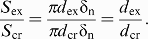
In the present study, radial nozzles were examined with exit to throat cross-section area ratio equal to Sex/Scr = 4. For an ideal gas flow at the exit from the radial nozzle, the latter value corresponds to Mach number M ∼3 (or, more precisely, 2·94). The latter value of M can be obtained using the well known gas dynamic formula
19

Aluminium powder (ASD-1, spherical, average particle size 36 μm, RUSAL Company, www.rusal.ru), copper powder (PMS-1, dendritic, electrolytic, average particle size 64 μm, Uralelectromed Company, www.elem.ru) and nickel powder (PNE-1, electrolytic, average particle size 69 μm, Novozep Company, www.novozep.ru) were used to spray coatings with air used as the working gas at temperatures T0 = 500, 700 and 750 K respectively. The prechamber pressure p0 was within the interval 1·5–1·8 MPa.
Sections of either steel pipes (in deposition of aluminium and copper coatings) or aluminium pipes (in deposition of nickel coatings) of length ranging from 15 to 30 cm were used. The internal surface of the pipe samples was a premachined (on a lathe) surface subsequently given a sandblasting treatment. The pipe samples were sandblasted using standard equipment whose abrasive jet fell onto the internal pipe surface at a very small angle.
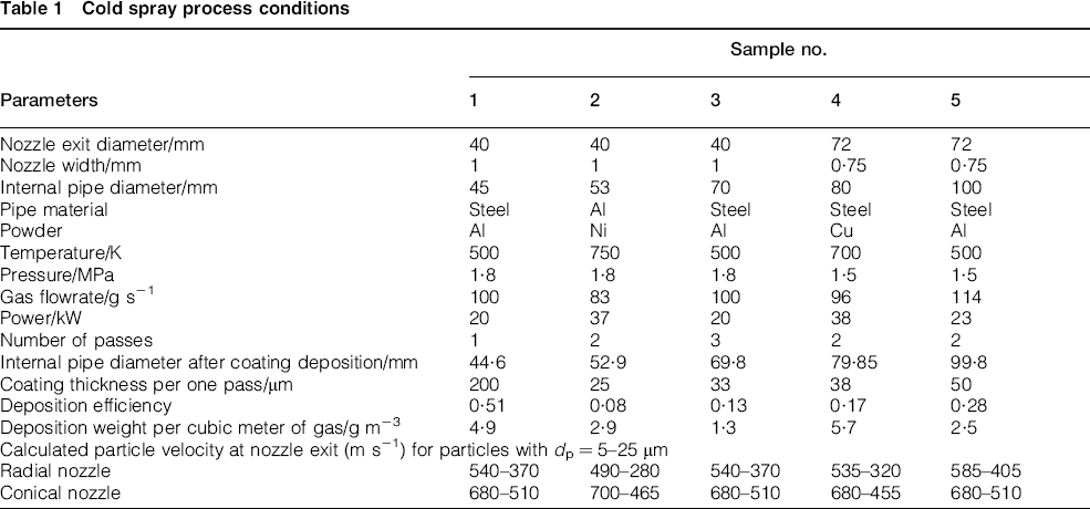
The coating deposition process was as follows. The first pass, with the radial nozzle assembly moving inside the pipe, was done without feeding the nozzle with the powder. This pass was used to preheat the pipe sample with the hot air from the inside. The second pass, with the nozzle assembly moving back out of the pipe, was implemented with the powder feed, which resulted in deposition of a coating on the internal pipe surface. Repeating this procedure several times assisted to increase the coating thickness. The travel velocity of the nozzle assembly was 5 mm s− 1. The cold spray conditions for all the samples used in the present study are summarised in Table 1.
Cold spray process conditions
The particle velocities at the exit from the radial nozzle were measured using the three-pulse laser shadowgraph method. The duration of the laser pulses was 20 ns; the second and third pulses illuminated the jet 200 and 600 ns respectively later than did the first laser pulse. The transfer factor of the optical system was 2, which allowed us to record the real fields of view sized ∼5 × 4 mm on a camera. All the three images taken with the three laser pulses were recorded in one and the same camera frame. Detailed explanation of the technique can be found elsewhere. 25
The Pitot tube measurements helped us to study the supersonic part of the radial jet.
Results and discussion
Before performing the cold spraying experiments, visualisation tests and Pitot tube measurements of the non-heated radial air jet were carried out. This was done using the 72 mm radial nozzle assembly with different nozzle widths and with different implemented prechamber pressures (in the range from 1·0 to 2·5 MPa). Typical patterns of radial jet exhaustion and impingement onto a flat substrate surface are shown in Fig. 3. In the supersonic part of the radial jet, three to five ‘barrels’ looking in Fig. 3a as concentric circles are observed. Simultaneously, oblique shock waves are observed inside the radial nozzle (Fig. 3b). Obviously, because of the presence of the shocks, the isentropic model (i.e. equation (2)) could not be used to accurately describe the gas flow inside the radial nozzle under the adopted experimental conditions.
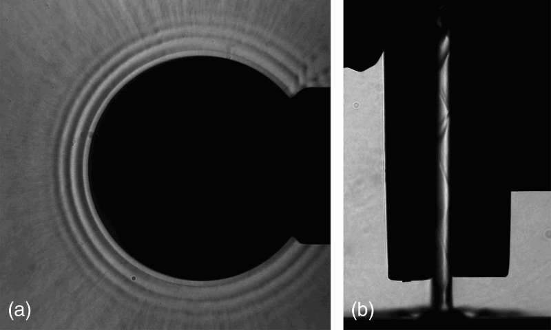
Photos of radial jet in planes a parallel and b normal to jet spreading plane dex = 72 mm, δn = 2 mm, p0 = 1·5 MPa
To predict the typical range of the internal diameters for the pipes that could be coated from the inside using the radial nozzle assembly, we have determined the supersonic length of the radial jet ls (i.e. the distance from the nozzle exit at which the gas velocities in the core of the radial jet remained supersonic). According to Fig. 4, on increasing the prechamber pressure and nozzle width, the length ls grows in magnitude within the range from ∼5 to 15 mm. Hence, one can expect that the maximum internal pipe diameter admitting the coating process does not exceed 30 mm over the exit diameter of the radial nozzle. Note that the data reported here present just a rough estimate. For more exact determination of acceptable pipe diameters, a detailed comparison between the properties of produced coatings is required.
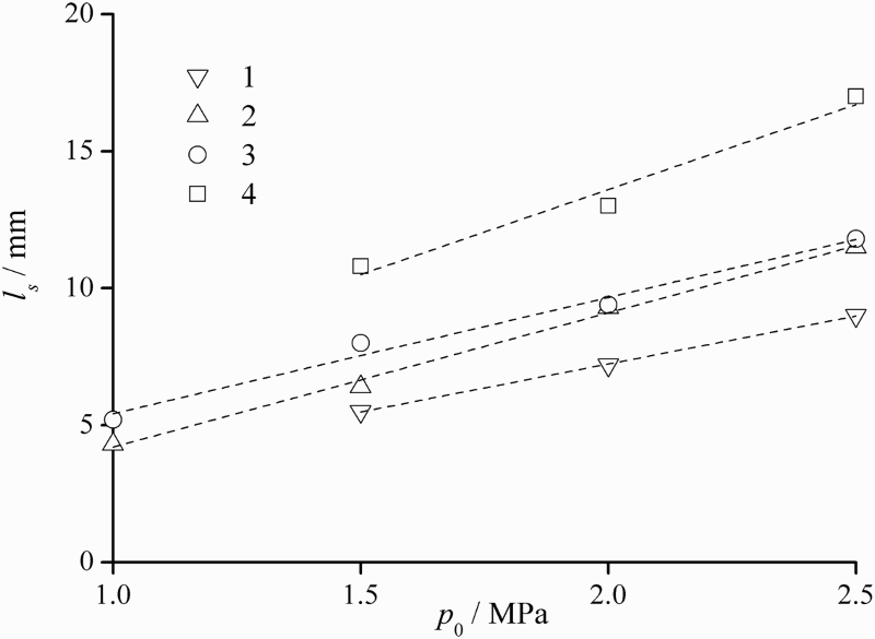
Dependence of supersonic length of radial jet on prechamber pressure and nozzle width dex = 72 mm: 1, δn = 0·5 mm; 2, δn = 1 mm; 3, δn = 1·5 mm; 4, δn = 2 mm
The use of the 72 and 40 mm radial nozzle assemblies greatly facilitated the production of aluminium and copper coatings on the internal surfaces of steel pipes ranging in internal diameters from 80 to 100 mm and from 45 to 70 mm respectively. In addition, nickel coatings were successfully deposited onto the internal surface of aluminium pipes of internal diameter 53 mm using the 40 mm radial nozzle assembly.
For example, Fig. 5a and b shows photos of one and the same steel pipe of internal diameter 100 mm (sample no. 5) before (Fig. 5 a) and after (Fig. 5 b) the cold spraying of an aluminium internal coating performed using the 72 mm radial nozzle assembly. Figure 5c and d shows photos of pipes of different internal diameters with aluminium and copper internal coatings (samples nos. 1 and 4 respectively). Figure 6 shows photo of the cross-section of a steel pipe with an internal aluminium coating (sample no. 1). It is seen that the coating top layer is very porous but coating bottom layer is dense and tightly joined to the substrate.
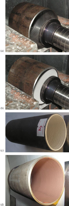
Photos of coated steel pipe samples: a, b one and same steel pipe sample (sample no. 5) before (a) and after (b) cold spray deposition of internal aluminium coating; din = 100 mm, 72 mm radial nozzle assembly, δn = 0·75 mm, p0 = 1·5 MPa, T0 = 500 K, c sample no. 1 with deposited aluminium internal coating, din = 45 mm, 40 mm radial nozzle assembly, δn = 1 mm, p0 = 1·8 MPa, T0 = 500 K, d sample no. 4 with deposited copper internal coating, din = 80 mm, 72 mm radial nozzle assembly, δn = 0·75 mm, p0 = 1·5 MPa, T0 = 700 K
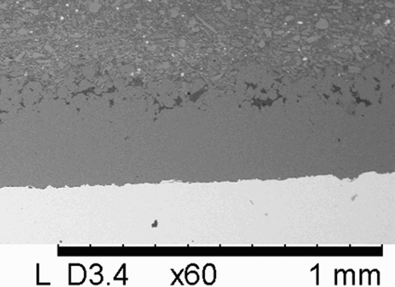
Photo of cross-sectional cut of steel pipe with internal aluminium coating, din = 45 mm (sample no. 1)
The measured mean aluminium particle velocity at the exit of 40 mm radial nozzle assembly at p0 = 1·5 MPa and T0 = 300 K proved to be 287 ± 5 m s− 1 with standard deviation 39 m s− 1. Note that the used diagnostic system does not register fine particles because of their low contrast caused by the high velocities of these particles and turbulent fluctuations. With the low contrast of fine particles taken into account, the mean size of particle images was evaluated as ∼ 25 μm.
For particle velocity calculations, a model was used that was previously developed for supersonic nozzles of rectangular cross-section. 19 This model takes into account the presence of boundary layers on the nozzle walls. Note that a sector of any radial nozzle can be represented as a supersonic part of a rectangular cross-section nozzle.
For p0 = 1·5 MPa and T0 = 300 K (i.e. under actual particle velocity measurement conditions), the calculation of the velocity of aluminium particles sized 25 μm at the exit of the 40 mm radial nozzle assembly has yielded a value 306 m s− 1. This value is only 6·6% larger than the measured one, proving the adopted model to be valid. Table 1 indicates the calculated velocities of particles ranging in size from 5 to 25 μm at the exit of the examined radial nozzle assemblies under the adopted cold spray conditions. In addition, Table 1 summarises the calculated velocities of aluminium, copper and nickel particles 5–25 μm in size at the exit of a conical nozzle at p0 = 1·5 MPa and T0 = 500, 700 and 750 K respectively. The main dimensions of the conical nozzle were as follows: throat diameter, 3 mm; exit diameter, 6 mm; supersonic length, 100 mm.
The above estimates show that the particle velocities that can be achieved in the cold spray process implemented using the radial nozzle assemblies are typically 100–200 m s− 1 lower than the particle velocities that can be achieved with the help of conical nozzles. Most likely, the cold spraying conditions typical of radial nozzle assemblies ensure a higher pipe internal surface temperature in comparison with axisymmetric nozzles. The higher substrate surface temperatures entail the possibility of depositing coatings at lower particle impact velocities. 19 This fact probably explains the successful formation of coatings under the conditions adopted in our experiments. Estimations also show that particles sized 1–5 μm typically achieve velocities ∼700–500 m s− 1. Thus, one way towards optimisation of the cold spray process implemented with the help of a radial nozzle assembly is the choice of suitable powders.
Our experiments show that, with the examined radial nozzle assembly, it was possible to produce internal coatings on pipes of various internal diameters. For example, the 40 mm radial nozzle assembly could be successfully used to deposit coating onto the internal surface of pipes ranging in internal diameters from 45 to 70 mm. However, a distinct reduction in the thickness of deposited coatings was observed for pipes with internal diameter of 70 mm than for those with diameter of 45 mm (see Table 1). The latter could not be explained only by that internal pipe diameter was greater, but was presumably due to a decrease in particle velocities and temperatures as well as in the pipe surface temperature. Hence, one can expect that using the 40 mm radial nozzle assembly for depositing coatings on pipes with internal diameters greater than 70 mm will result in further reduction of the coating thickness and, hence, the deposition efficiency. This result complies with the data of Fig. 4. Thus, for depositing coatings on the internal surface of pipes of larger internal diameters, it is necessary to increase the nozzle exit diameter of the radial nozzle. For instance, the 72 mm radial nozzle assembly could be used to reach this goal.
Conclusion
In the present study, the problem of coating production on internal pipe surfaces by the cold spraying method was addressed. A new nozzle assembly was designed with a radial supersonic nozzle formed by two co-axial discs separated with some distance. In this assembly, the working gas flow seeded with particles fed from the axial zone spread in the gap between the two discs at supersonic velocities, thus accelerating the particles to high velocities. For the present preliminary study, two radial nozzle assemblies have been manufactured with nozzle exit diameters 72 and 40 mm. First, visualisation tests and Pitot tube measurements of the airflow were performed inside and outside the 72 mm radial nozzle assembly. The measurements proved helpful in predicting the range of internal pipe diameters in which the nozzle assembly could be used to coat the internal pipe surfaces. Second, the 72 and 40 mm radial nozzle assemblies were found to greatly facilitate the production process of continuous aluminium and copper coatings on the internal surface of steel pipes with internal diameters ranging from 80 to 100 mm and from 45 to 70 mm respectively. Nickel coatings were successfully deposited onto the internal surface of aluminium pipes with internal diameter of 53 mm as well. Third, aluminium particle velocities at the exit of the 40 mm radial nozzle assembly were measured. For calculation of particle velocities, a model was used previously developed for supersonic nozzles of rectangular cross-section. This model takes into account the presence of boundary layers on the nozzle walls. A good agreement between the calculated and measured particle velocities was obtained. Next, the particle velocities have been calculated under the actual cold spraying conditions, and found those velocities to be lower than the particle velocities being typical of axisymmetric nozzles. Finally, the typical mass and energy consumption characteristics of the developed process have been calculated as well as the deposition efficiencies achievable under typical experimental conditions. The obtained values have allowed us to evaluate the cost of potential introduction of the cold spray process into pipe production.
Footnotes
Acknowledgments
The authors would like to express their gratitude to G. V. Trubacheev, N. S. Ryashin, F. V. Orlenko and V. S. Shykalov for assistance in the experiments.