
Abstract
The present work reports the synthesis of dip coated MgO nanoflower thin films. The films are developed without employing any capping agent and catalyst. A simple chemical deposition technique is adopted for this purpose. The MgO nanoflower thin films are characterised by X-ray diffraction, field emission scanning electron microscopy, transmission electron microscopy, high resolution transmission electron microscopy and the related energy dispersive X-ray spectroscopy techniques. The results establish the phase purity and microstructural details of the MgO nanoflower thin films. These results are explained in terms of a proposed mechanism that suggests the growth process for the MgO nanoflower structures.
Introduction
Magnesium oxide (MgO) is a very important material for wastewater treatment, photovoltaic device component, synthesis of phase changing composite, biodegradable nanoparticle for drug delivery and high capacity charge storage device.1–5 It is also emerging as a designer growth template that can be used as a substrate for deposition of thin film. 6 In spite of the wealth of global literature,7–43 there is no report on the exploitation of nanoflower (NF) MgO thin films for optoelectronic device fabrication. The prospects of new technological application and the possible extension of the domain of surface engineering to advanced optoelectronic devices are the basic motivations behind the present unique attempt.
The NF MgO thin films are deposited in the current work by a simple green technique. The commercially available soda lime silica (SLS) glass is used as substrate. Thus, it demonstrates the very first step towards cost effective fabrication of smart optoelectronic devices through appropriate surface engineering approach in future.
The MgO thin films are typically prepared by pulsed laser deposition, 7 chemical vapour deposition (CVD), 8 sol–gel based deposition,5,9 spin coating, 10 dip coating 11 and electron beam evaporation 12 techniques. The Mg based structures in general13,14 and the porous MgO nanostructure in particular 15 show high efficacy towards toxic waste removal. This is one of the prime motivations to synthesise MgO nanostructures.16–34
The typical examples include for instance but not necessarily limited to synthesis of MgO nanorods (NRs), nanowires (NWs), nanolayers, nano-multilayers and carbon nanotube based composites.16–26 Heating, thermal evaporation and CVD are utilised to produce MgO NRs, NWs, nanotadpoles, nanodendrites, nanobelts, nanotubes, nanocubes, orthogonally branched nanostructures, nanotrees and NFs.27–32 Recent reviews highlight the importance of MgO and other nanostructures for advanced surface engineering and other functional applications.33,34
High temperature (e.g. 650–950°C) exposure of either Mg compound or metallic Mg also produce MgO nanostructures.35,36 Intelligent control of oxygen pressure during oxidation of metallic Mg leads to formation of polyhedral MgO nanocages. 37 These nanocages act as efficient electron mediator. Hence, such structures provide highly sensitive amperometric glucose biosensor. 37
The fabrication of MgO nanotubes, nanotube clusters and large scale arrays of MgO nanosheets is also reported.38–40 MgO nanoshells are prepared by high pressure magnetron sputtering of Mg target. 41 Hollow mesoporous MgO is synthesised from magnesium acetate tetrahydrate and ammonium oxalate. 42
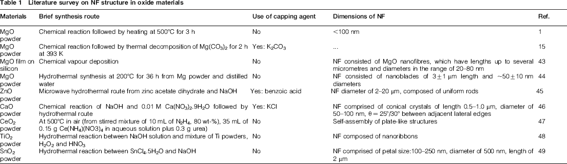
A typical representative literature survey1,15,43–49 on synthesis of MgO and other NF structures in oxides is summarised in Table 1. It shows that there are reports on synthesis of ZnO, 45 CaO, 46 CeO2, 47 TiO2, 48 and SnO2 49 NF structures. However, the total quantum work reported on MgO NF synthesis appears to be rather insignificant.1,15,43,44 For instance, there is merely one report on MgO NF formation in a thin film. 43 There are only three reports on MgO NF formations in powders.1,15,44 Earlier attempt to synthesise MgO NF in a thin film requires the use of the costly CVD process. 43
Literature survey on NF structure in oxide materials
The objective of the present work is to synthesise MgO NF thin film on commercially available SLS glass substrate. It is achieved by a simple, inexpensive, green dip coating method. Finally, the films are thoroughly characterised by conventional means such as the X-ray diffraction (XRD), field emission scanning electron microscopy (FE-SEM), transmission electron microscopy (TEM), high resolution TEM (HRTEM) and the related energy dispersive X-ray spectroscopy (EDAX) techniques. As mentioned earlier, the primary motivation behind the present unique attempt lies in the possible extension of the domain of surface engineering to advanced optoelectronic devices. To the best of our knowledge, the present report is the very first of its kind.
Experimental
The MgO NF thin films are grown by heating the precursor Mg(OH)2 thin films at a temperature of ∼450°C for 2 h in air. The precursor films are chemically deposited by dip coating method on the commercially available SLS glass substrates. Thereafter, they are kept in vacuum desiccators to avoid further contamination with environment. The details of the experimental procedure to deposit Mg(OH)2 are already reported by Das et al., 50 Mukhopadhyay et al., 51 Das et al., 52 Das et al. 53 and Chanda et al. 54 Hence, it shall not be repeated here for the sake of brevity.
The deposited thin films have average thickness of 220 ± 19 nm. The film thickness is measured by profilometry (Talysurf, Taylor Hobson, UK) technique. Phase analysis of the deposited film is carried out by XRD technique (PANalytical X'pert Pro MPD Diffractometer, The Netherlands). Microstructural characterisation of the synthesised thin film is carried out by FE-SEM (model Supra VP35, Carl Zeiss, Germany), TEM (model Tecnai G2 30, S-Twin, 300 KV, FEI, The Netherlands), HRTEM in the same transmission electron microscope (model Tecnai G2 30, S-Twin, 300 KV, FEI, The Netherlands), selected area electron diffraction (SAED) and the related EDAX techniques.
Results
Phase analysis
Typical XRD pattern of the chemically deposited thin film is shown in Fig. 1. The data presented in Fig. 1 show the characteristic peaks of phase pure MgO corresponding to the (200) and (220) planes (JCPDS 18-1022). For the (200) plane, the experimentally measured d value is 2.11 Å. In the case of the (220) planes, the corresponding d value is 1.49 Å. These d values are in excellent match with those from JCPDS 18-1022.
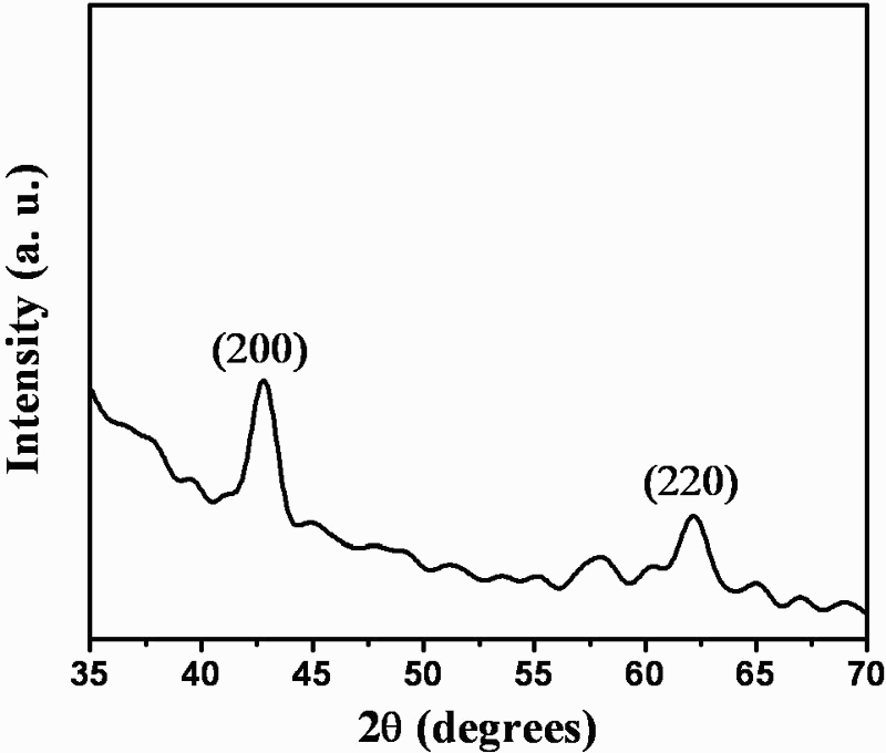
Typical XRD pattern of dip coated MgO thin film
After correcting for the machine background effects, the crystallite sizes are calculated from the XRD data (Fig. 1) using the Scherer's relation. The crystallite sizes are estimated as 11.9 nm for the (200) and 7.76 nm for the (220) planes. Thus, the average crystallite size is evaluated as ∼9.83 ± 2.92 nm. Following the method given by Chanda et al., 54 the lattice constant for the MgO thin films is calculated as a = 4.2212 ± 0.0009 Å. This value of the lattice constant matches closely with literature data. 54
Microstructural investigations
FE-SEM studies
The microstructures of MgO thin film as revealed by FE-SEM images obtained at progressively higher magnifications are shown in Fig. 2a–d. The typical low magnification photomicrograph depicts the undoubted presence of the MgO NFs (Fig. 2a).
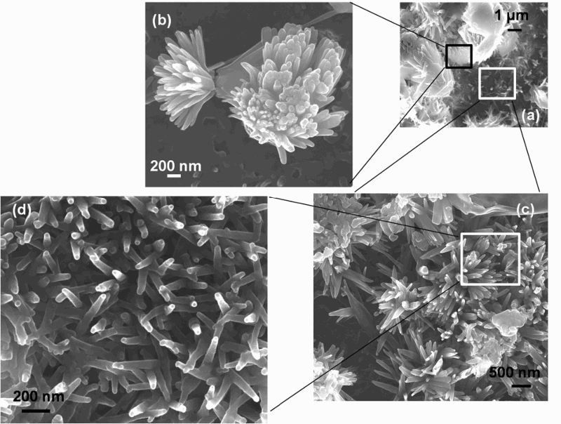
FE-SEM views of microstructure at a low and b–d progressively higher magnifications: a MgO thin films; b individual NFs; c assembly of NFs; d NRs assemble to form NFs
The structure of individual NFs is revealed in the photomicrograph presented in Fig. 2b. The local orientation of the individual NFs is illustrated by the photomicrograph shown Fig. 2c. It is evident from the photomicrograph depicted in Fig. 2d that a large number of NRs self-assemble and form the NFs. The typical length of the NRs spans a range of ∼400–800 nm. The typical width of the NRs spans a range of ∼100–150 nm. Thus, the aspect ratio of the NRs spans a range of ∼4–6. The local angular orientation θ (Fig. 2d) of the NRs varies in a large range (e.g., 3° < θ < 178°).
TEM studies
Typical TEM photomicrographs of the MgO NFs are shown in Fig. 3a–d. The nanoparticles appear to have a great tendency to remain agglomerated (Fig. 3a). This tendency is expected from their surface charge considerations.
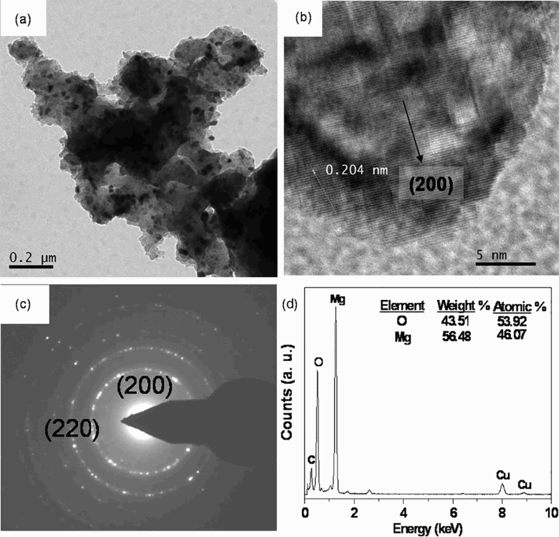
TEM photomicrographs of MgO NF: a bright field image at low magnification; b HRTEM of photomicrograph shown in a, and corresponding c SAED pattern and d EDAX spectra
The HRTEM image presented in Fig. 3b reveals that the MgO synthesised in the present work is structurally uniform. The magnitude of the resolved spacing corresponding to the (200) lattice plane is ∼0.204 nm (Fig. 3b). This magnitude of the interplanar spacing is close to that (e.g., d = 0.211 nm) measured from the XRD data (Fig. 1).
The SAED pattern (Fig. 3c) shows the distinct presence of diffraction circles corresponding to the (200) and (220) planes. The corresponding experimentally measured d values are 1.94 Å for the (200) and 1.49 Å for the (220) planes. The magnitudes of these d values are in reasonable match with those [e.g., 2.11 Å for the (200) and 1.50 Å for the (220) planes] obtained from the XRD data (Fig. 1).
From the typical representative EDAX analysis (Fig. 3d), the MgO films appear to be slightly magnesium lean and oxygen rich. There can be two sources for this excess oxygen. It may partially arise from the SLS glass substrate. 55 It can also arise due to the pick up of moisture 56 from the surrounding atmosphere. The peaks corresponding to carbon and copper (Fig. 3d) occur respectively due to the carbon coating and the supporting copper grid.
Discussions
The present results (Figs. 1–3) confirm the development of phase pure MgO NF thin films. Only a handful of literature1,15,44 reports on synthesis of MgO NFs in powders. Literature report on synthesis of MgO NFs in thin films 43 is even rarer (Table 1).
Considering the importance of NFs in thin films in general and that of MgO NFs in thin films in particular in the field of drug delivery, high capacity charge storage device and designer growth templates, a new qualitative model (Fig. 4) is proposed below about their growth mechanism. The proposed model on MgO NF growth mechanism in the dip coated thin films originates from the extensive evidence (Fig. 2a–d) obtained from the FE-SEM based investigations.
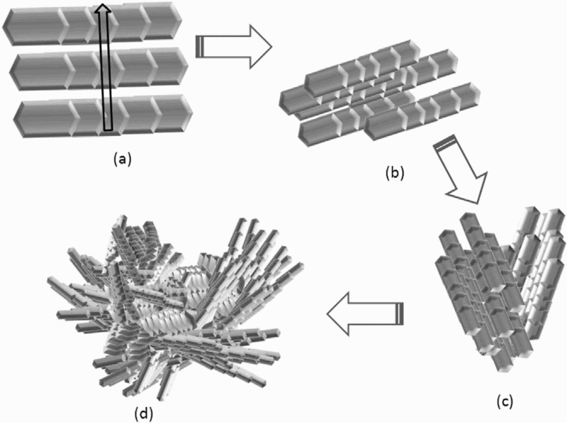
Schematic of different stages of formation of MgO NF: a initial transformation of Mg(OH)2 to MgO nuclei; b heterogeneous MgO layer growth; c further nucleation and growth of MgO layers into NRs; d self-assembly of MgO NRs to form NF
The MgO nuclei start to seed out from the heat treatment of the Mg(OH)2 nuclei present in the precursor film.50–54 As a result, an MgO seed layer forms as the first step (Fig. 4a) in this heterogeneous nucleation process. The very existence of such a seed layer promotes further growth of the MgO nanocrystallites. The growth most likely occurs through a localised reduction of the thermodynamic energy barrier.
Consequently, within a small time, a surge in heterogeneous isolated nucleation of the MgO nanocrystallites takes place. This step paves the way for further growth of many MgO nanocrystallites. These MgO nanocrystallites act as further active nucleation sites.
When magnesium hydroxide transforms to MgO, there is a very important structural rearrangement that occurs. 17 Here, the layers of MgO6 octahedra in Mg(OH)2 move to join each other first. As they join, a continuous three-dimensional face centred cubic (FCC) structure is formed. However, in the course of this exercise, one-half of the oxygen atoms between the neighbouring layers are removed.
The hexagonal Mg(OH)2 is a layered CdI2 type structure. It has the ABABAB stacking sequence. Here, the (OH)− layers are the A layers. The interstitial spaces of these A layers are filled by the B layers. The B layers are formed by the Mg2+ ions. Heating at 450°C for 2 h in air transforms the ABABAB stacking sequence of Mg(OH)2 structure into MgO. It is already well established that MgO has an FCC structure with a ABCABC stacking sequence. 17
The most preferred direction of the present MgO NRs is [200] (Fig. 1). It is suggested that when the growth of an NR is restricted to only within a particular preferred plane, the growth along a third axis is compromised because it is energetically unfavourable (Fig. 4b).
Of course, there can be local changes in both length and orientations of the NRs (Figs. 2b and 4b). The prevalent thermodynamics of the whole process necessarily guides such a growth process.57–60 The most conducive growth condition for the NRs (Fig. 4c) is the one that minimises the energy requirement.57–58 The growth and orientations of the NRs are thus governed by the minimisation of the local Gibb's free energy of the whole process.
It is proposed that it happens on the existing nuclei due to the preferential growth of the ABC faces in a direction that is perpendicular to the stacking direction (Fig. 4c). Once the NRs grow, they self-assemble into NFs (Figs. 2d and 4d).
The magnitude of the force that drives this process is governed by the localised requirement of minimum surface energy.59,60 Nevertheless, the stochastic nature of the NF growth (Figs. 2a–c and 4a–c) fingers an important pointer.
It suggests that there is a local competition between the energy minimisation requirement and thermodynamic constraints of the overall particle growth kinetics. It is the final result of this localised competition that dictates the final equilibrium structure of the individual NFs.
During the process of self-assembly, atoms, molecules, particles and other shapes make their own assemblage into special functional structures. 58 The formation of such special functional structural assembly is in turn driven by the requirement of minimisation in the system energy.57,59,60 However, it must be emphasised that further dedicated experimentation will be necessary to verify the validity of the schematic picture presented here.
Conclusion
The MgO thin film NF structure is developed on commercially available SLS glass substrates by a chemical deposition technique. The process is simple, green as well as cost effective. It does not require any capping agent and/or catalyst. The NFs comprise locally oriented self-assembly of NRs. The NRs are ∼400–800 nm long and ∼100–150 nm wide. It is proposed that the growth and orientations of the NRs and the consequent self-assembly of these NRs into NFs are governed by the minimisation of the local Gibb's free energy of the whole process.
Footnotes
Acknowledgement
The authors (except A.D.) acknowledge the kind support and encouragements received from Director, CSIR-CGCRI, during the course of the present work.