
Abstract
In this paper, the sliding wear behaviour of nickel based superalloy pin was investigated on disc with two different coatings. The plasma sprayed NiCr–Cr2O3 coating and Al2O3+40%TiO2 (A40T) coating were used on the disc for wear studies. The sliding wear tests were performed on dry conditions at room temperature for a constant sliding velocity for two different applied loads (5 and 10 N). The mass loss, wear resistance and coefficient of friction between the pin and disc were studied during investigations. The wear mechanism involved in the NiCr–Cr2O3 coatings is three-body abrasion and Cr2O3 being the third body between pin and disc. The wear rate is high due to the applied load and suppressed cracks. In A40T coating, the minute debris collected on the surface of the coatings acts as a solid lubricant and reduces friction and wear rate. The SEM and energy dispersive spectroscopy analysis were also carried out for characterisation studies on pin after wear studies. The life of nickel pin on A40T coatings is found superior than the NiCr–Cr2O3 coated disc.
Introduction
Wear and friction are the major scientific and technological challenges addressed by many automotive industries and research scientists. 1 Most engineering components are susceptible to failure due to wear and other tribological phenomenon leading to breakdown of the engineering system. One of the foremost methods for improving the tribological properties is surface modifications. The surface modifications are carried out through various processes such as thermal spraying, physical/chemical vapour deposition, mechanical attrition, laser/electron beam method, etc. It also improves the corrosion and wear resistance of the tribological components used in industry. Thermal spraying is mostly used for surface modification, and it plays a vital role in petrochemical industries, oil refineries, gas turbine engines and for other automobile applications. Thermal spray process can be differentiated based on the development of heat source used for coating. 2 Thermal spray coatings are classified as vacuum plasma spraying, low pressure plasma spraying, atmospheric plasma spraying, high frequency pulse detonation and high velocity oxygen fuel spraying.3–5
Plasma sprayed coatings is one of the most versatile and best coating techniques to provide better wear resistance and corrosion resistance. The nickel based gradient coatings are widely used in gas turbine applications. The plasma sprayed alumina–titania coatings have superior mechanical properties and adhesion strength compared to exiting coatings like as NiCrAlY and yttria stabilised zirconia coatings. 6 The slight damage due to abrasion/erosion in the gas turbine component leads to reduction in pressure affecting engine efficiency simultaneously. To enhance the performance of gas turbine engine and to increase the corrosion and wear resistance of the engine components, suitable coatings are suggested. There is no certain rule followed to suggest or to select coating materials for turbine engine components due to the complicated nature of the working environment. 7
The main aim of this research is to develop novel coatings for gas turbine components to enhance tribological properties. The gas turbine engine components are made of nickel alloys. 8 To increase the tribological properties of the gas turbine component, two different coatings, NiCr–Cr2O3 and Al2O3–40% TiO2, are selected for investigations.
Materials and methodology
Materials
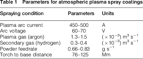
The nickel based superalloy with an exact chemical composition of Ni 54.5 wt-%, Cr 21.25 wt-%, Co 12.20 wt-%, Mo 7.82 wt-%, Fe 1.9 wt-%, Al 1.05 wt-%, Mn 0.08 wt-% and C 0.06 wt-% with traces of Si, Ti, Cu and B is used as a work material. The samples are prepared using wire electrical discharge machining to a size of Ø8 × 30 mm as pin. The Al2O3–40 wt-%TiO2 and Cr2O3–25 wt-%NiCr coatings were deposited on Ø80 mm disc by atmospheric plasma spraying method using a standard coating parameter (Table 1). 9
Parameters for atmospheric plasma spray coatings
The surface morphology of the NiCr–Cr2O3 and A40T coatings is shown in Figs. 1 and 2. Through literature, it has been found that the increase in weight percentage of titania in the alumina–titania will decrease the porosity. 10
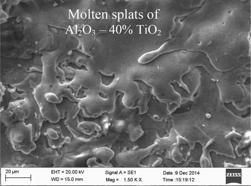
Surface morphology of A40T coatings before sliding wear investigations
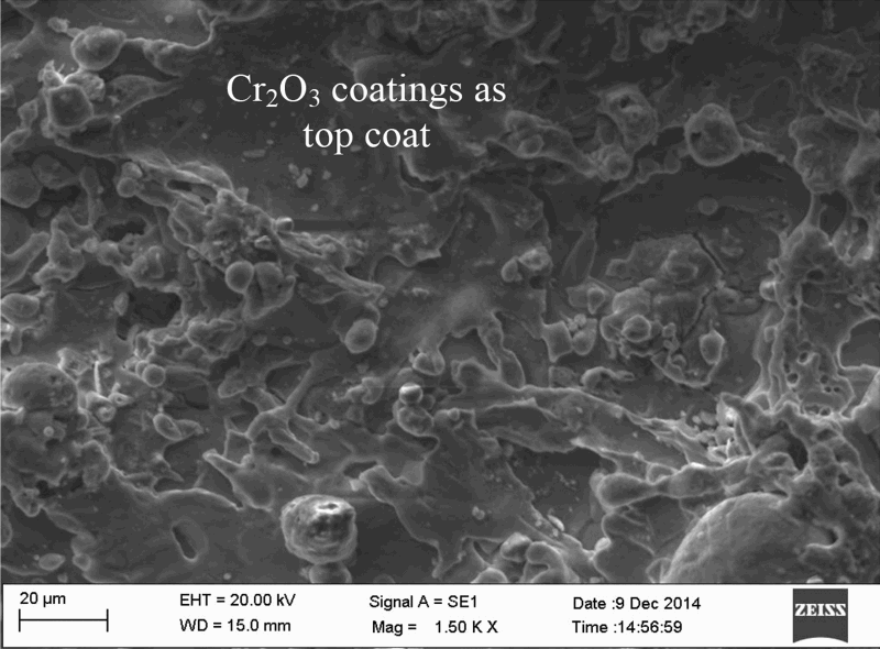
Surface morphology of NiCr–Cr2O3 coatings before sliding wear investigations
Methodology
The dry sliding wear behaviour of nickel pin on plasma sprayed coatings is carried out on sliding wear (pin on disc) tribometer. The ASTM G99-5 (2010) standard procedure is followed to conduct the experiment and data calculations. The wear studies are carried at two different loaded conditions (5 and 10 N) at room temperature for a constant velocity (1 m s− 1) and for a sliding distance of 3000 m. The difference in mass change for pin and disc (before and after wear study) is measured using digital microbalance to an accuracy of 0.01 mg. The depth of wear and the coefficient of friction are calculated with respect to time from the data acquisition systems coupled with load sensors. The surface morphology of the pin and disc after wear studies is further investigated with a scanning electron microscope (SEM) (Zeiss) and energy dispersive spectroscopy (EDS) (Brukers) for a detailed study.
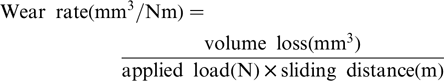
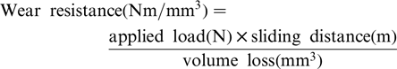
Test calculations
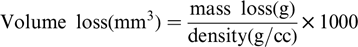
The mass loss measured with respect to each wear conditions is used to calculate the following significant tribological results, such as volume loss, wear rate and wear resistance.
Results and discussion
Sliding wear and coefficient of friction
During unidirectional sliding wear experimentation, the depth of wear (μm) and coefficient of friction (μ) are acquired through an inbuilt data acquisition system for investigation. The variation in depth of wear with respect and applied load is shown in Fig. 3. The depth of wear includes the sliding of pin and disc in contact. The increase in wear at an initial stage for few seconds shows the common wear phenomena for all the conditions. For an applied load of 5 N, a slight increase in wear was noticed between both the coatings and pin. Comparatively, wear depth of nickel pin with A40T coated disc shows less wear than that of NiCr–Cr2O3 coated disc. However, at 10 N loaded condition, rapid increase in wear is noticed with the pin on NiCr–Cr2O3 coatings than on A40T coatings. In NiCr–Cr2O3 coated disc, the Cr2O3 particles from the top coat has influenced the increase in wear and wear debris found at end of the experimentations. The fractured top coat particle (as debris) will increase the depth of wear due to applied load and suppressed cracks/pores on the Cr2O3 coat. The reduction in wear on the A40T coatings is due to the inherent property of TiO2 particles.
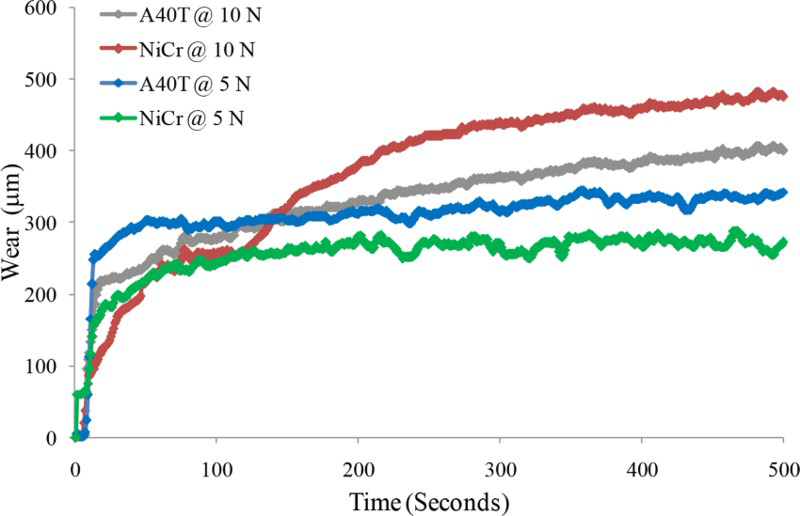
Progress of sliding wear with respect to applied load at constant velocity (1 m s− 1)
The variation in coefficient of friction with respect to time for applied load is shown in Fig. 4. The pattern trend shows the disparate changes in NiCr–Cr2O3 coated disc and A40T coated disc. The adhesion of solid particles over the contact area of nickel pin from A40T disc was found more. This solid particle in combination of titania thus reduces the coefficient of friction between the pin/disc interface. Similar result has been found in research articles published in the journals of international repute and standard tribological handbook.11–13 It is also confirmed that the nickel pin has a nominal wear and coefficient of friction at the lower applied load. With this evidence, the sliding wear behaviour is not ascertained, and still, the wear resistance is further calculated along with surface analysis and reported in detail.
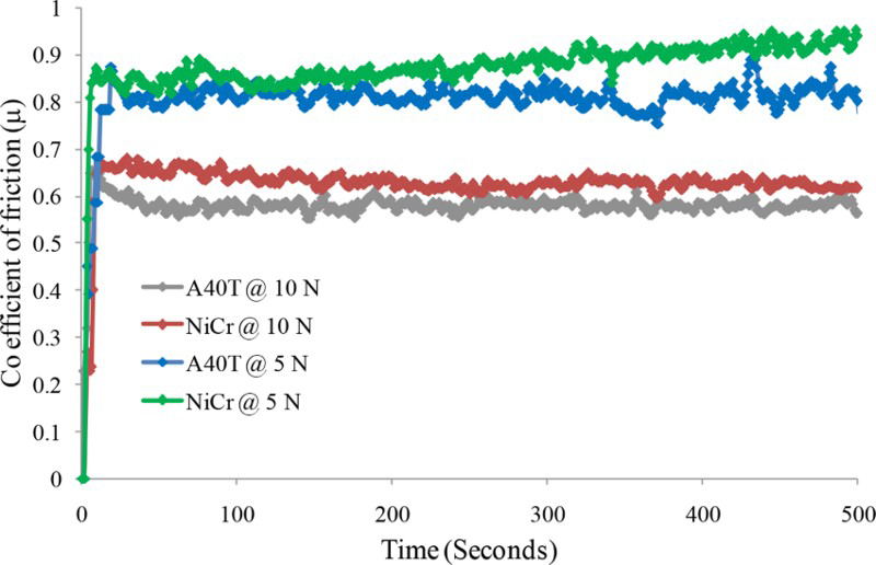
Variation in coefficient of friction with respect to applied load
Calculated mass loss and wear resistance
Figure 5 shows the calculated mass loss of pin and disc with respect to the coatings and applied load. The mass loss of the pin falls in the range of 10–20 mg for all the conditions. Maximum mass loss of the pin is observed with A40T coated disc under an applied load of 10 N. In A40T coated disc, the mass loss is 2–4 mg, and the mass loss in NiCr–Cr2O3 coated disc is very high when compared to the A40T disc. After completion of sliding wear studies, the NiCr–Cr2O3 coated disc is observed with the wear tracks and severe abrasion on the nickel pin. This is due to the abrasion of hard Cr2O3 particles from the top coat of the disc. The wear debris as a dark grey colour oxide particles were observed adhering to the contact area of the pin after sliding on A40T coated disc. It is due to the combined effect of lubrication cum abrasion of alumina and titania.
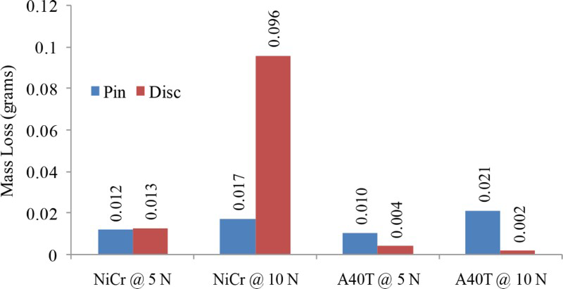
Difference in mass loss measured in pin and coated disc after investigations
The wear resistance of the coatings and the nickel pin is calculated from the mass loss and is shown in Fig. 6. The wear resistance of the nickel based pin is found to be in the range of 10–14 Nm mm− 3. The wear resistance of the NiCr–Cr2O3 coatings is found to be much less than that of the A40T coated disc. As the porosity is less with the presence of titania in the A40T coating, a dense coating is obtained causing increase in wear resistance. Mohanty 2 reported that the coatings with porosity will lead to high coefficient of friction, and dense coatings exhibit good wear resistance. It is also clear to infer that the wear behaviour of the nickel pin is severe while sliding on A40T and NiCr–Cr2O3 coatings. Above all, A40T coated disc shows better wear resistance on sliding with nickel pin than NiCr–Cr2O3 coated disc.
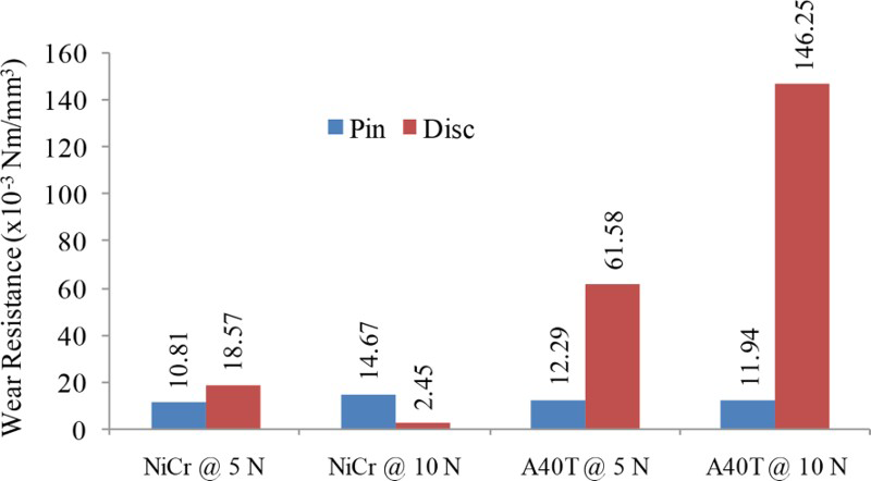
Wear resistance of nickel pin and coated disc with respect to applied load
Analysis (SEM) of nickel pin after sliding on NiCr–Cr2O3 coated disc
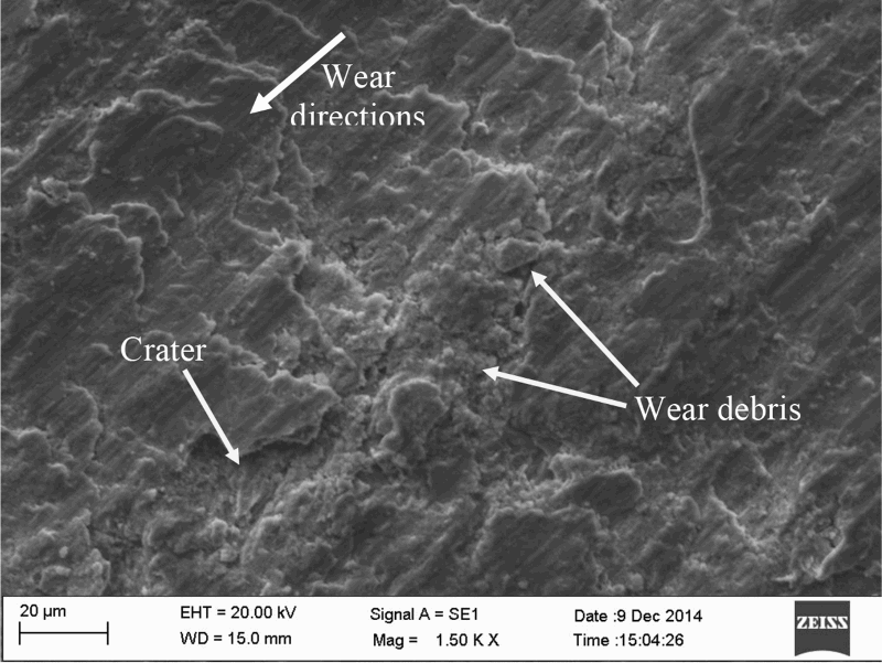
The surface morphology and wear behaviour of nickel pin after sliding on NiCr–Cr2O3 coated disc are shown in Figs. 7–9. The sliding wear direction is indicated through the arrow mark. The micrograph shows the wear track/scars appear parallel to the sliding direction of the pin. The scars in the pin are due to the abrasion of hard Cr2O3 particles and wear debris. The edges of the wear scars at 5 N loaded conditions are found to be smudged due to the cyclic load (Fig. 7).
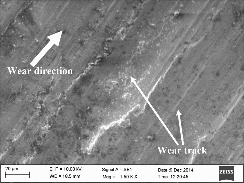
Wear morphology of pin applied with load of 5 N
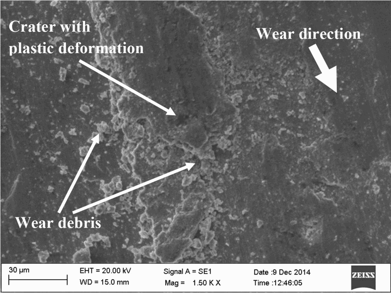
Wear debris and crater on pin after wear studies with applied load of 10 N
Wear morphology of NiCr–Cr2O3 coated disc
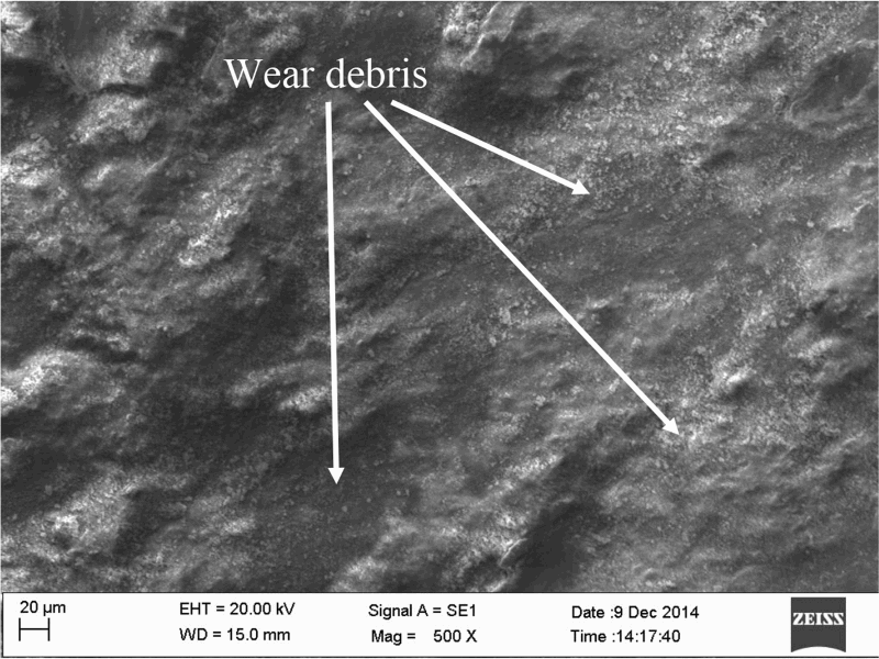
The sliding wear at 10 N load follows the three-body abrasive wear mechanism due to the wear debris of pin and coated disc. The wear debris adhere to the surface of the nickel pin even after completion of wear experimentation for a distance of 3000 m (Fig. 8). The wear morphology of the NiCr–Cr2O3 coated disc is shown in Fig. 9. The wear texture appears in the form of serration and cluster of wear debris collected in the crater region. The abrasion is the main wear mechanism found on NiCr–Cr2O3 coated disc, which is due to the action of hard abrasion wear debris particle. The crater and plastic deformations were also observed on the surface of the pin due to the cyclic surface fatigue fracture. Kazushige 14 and Chiba 15 also investigated and reported the same wear mechanism for Co–Cr–Mo alloy. The constant cyclic action of wear debris allows the contact surface area of the pin to undergo fatigue fracture. Thus, the overall wear mechanism of nickel pin and NiCr–Cr2O3 coated disc is partially due to fatigue wear and abrasion wear mechanism.
Analysis (SEM) of nickel pin after sliding on A40T coated disc
Figures 10–12 show the wear morphology of the nickel pin after sliding on A40T coated disc. The wear debris in the form of oxide particles found on the worn surface of the pin were investigated under the applied load of 5 N (Fig. 10). The distribution of wear debris is uniform, and the peaks of the wear scars also appear. Similarly, under 10 N applied load, the wear scars and grooves are clear (Fig. 11). The ridges and grooves on the surface are due to the abrasion of hard alumina particle. Vinay 1 reported the similar results on sliding wear behaviour of steel on plasma sprayed alumina coatings. The dark grey coloured oxide film was found on the surface of the worn pin. Thus, the formed film might have been active as a lubricant between the two contact areas of the pin and disc. However, with an applied load of 10 N, the wear scars and grooves are clear to notice. It is clear to observe that the edges of the wear tips are with the agglomeration of the oxide particles. The wear morphology of the A40T coated disc is shown in Fig. 12. The wear morphology of the disc appears different than that of the NiCr–Cr2O3 coated disc. The plastic deformation of the molten splat is the major wear morphology seen on the surface. It is due to the smudging of splats with the help of applied load and sliding velocity. No wear scars or wear tracks appear on the surface.
Distribution of wear debris in form of oxide particles on worn surface of pin
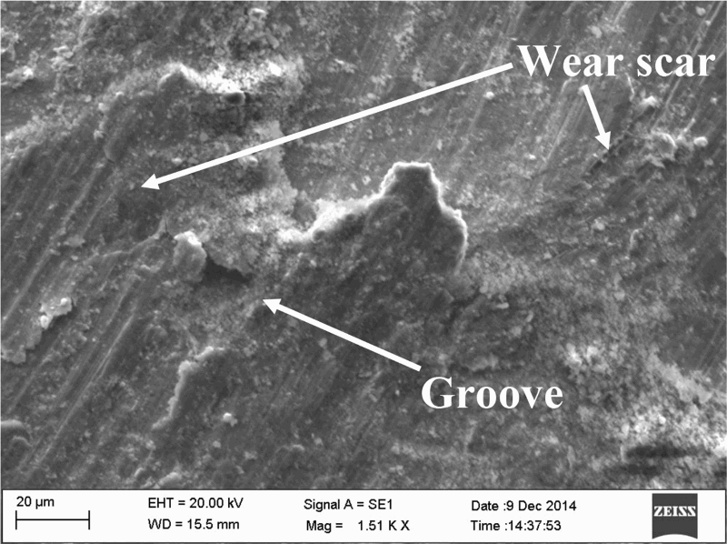
Wear morphology and adhesion of oxide particle on contact surface area of pin at applied load of 10 N on A40T disc
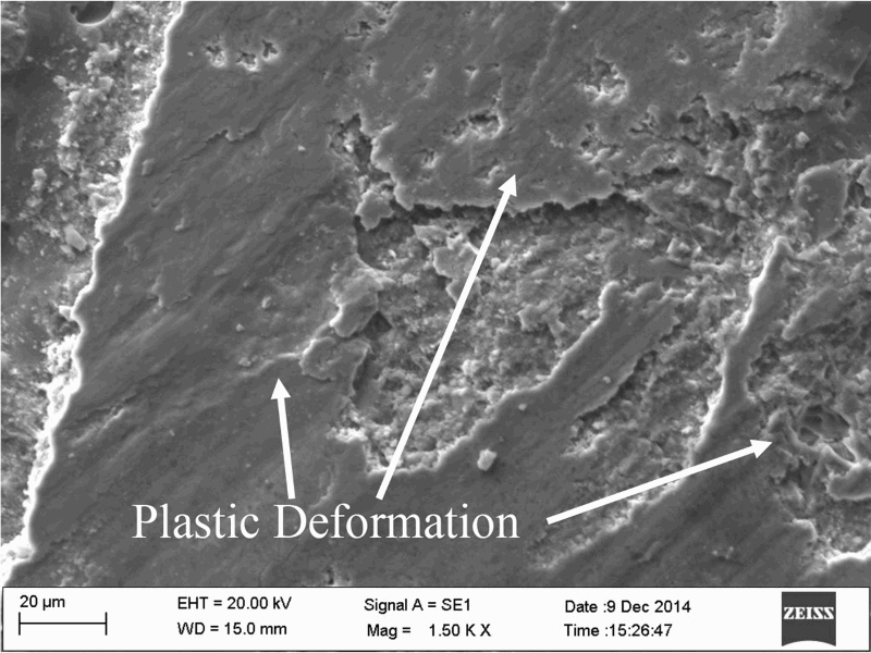
Wear and surface morphology of A40T coated disc
Analysis (EDS) on worn surface of nickel pin
Figure 13 shows the SEM image with the elemental proportion found through the EDS surface elemental analysis for sliding wear of nickel pin on NiCr–Cr2O3 coated disc. Ni and Cr are the major elements found on the surface of the worn surface pin. The small contribution of Co, Mo and Al was also found in the quantum analysis of EDS. Surprisingly, a quarter of the contribution is oxygen in the quantum analysis along with the alloying elements. It infers that the debris formed on the surface of the worn pin is in the form of oxides. The advancement of the EDS arrangements on the SEM machine gives the weight percentage of the possible combination of oxides. The possible oxides identified through the EDS systems are NiO (58.87%), Cr2O3 (27.41%) and Al2O3 (1.76%). The SEM and EDS result of nickel pin on A40T coated disc is shown in Fig. 14. The major elements found on the worn surface are Ti, Al, Ni, Cr, Fe and Co. The weight percentage of titanium is found to be more than that of other elements. The possible oxides in terms of weight percentage are as follows: TiO2–52.25%, Al2O3–25.97%, NiO–10.42%, Cr2O3–6.54% and FeO–2.90%. The majority of the debris on the worn surface is titania. The nature of titania is self-cleaning and hydrophobic. The combination of alumina and titania is found to be a protective layer formed on the surface of the worn pin. To examine the distribution of oxide elements, the EDS X-ray mapping was performed on the same surface (Fig. 15). Al and Ti are the major elements distributed evenly all over the worn surface of the pin. Ni and Cr are also found marked in the same worn surface. The distribution of oxygen is found stronger in the form of oxide scales. Thus, the titania and the alumina, which are hydrophobic and amphoteric in nature, protect the materials from severe degradations.
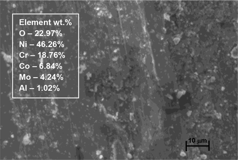
Analysis (EDS) on pin after sliding wear studies on NiCr–Cr2O3 coated disc
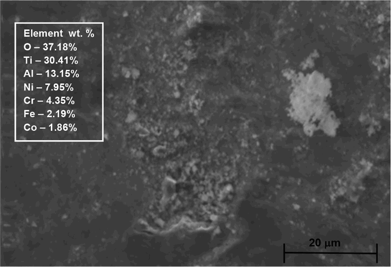
Analysis (EDS) on worn surface of pin with element (wt-%)
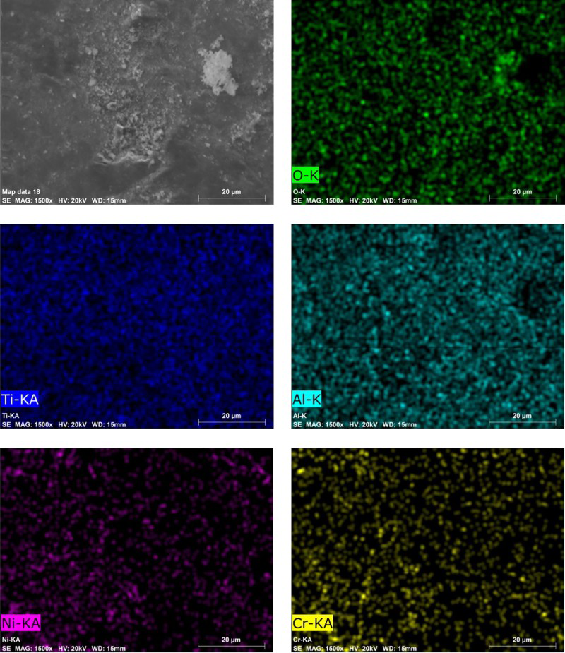
Image (SEM) and X-ray mapping of worn surface of pin
Conclusion
The sliding wear behaviour of nickel pin on NiCr–Cr2O3 and A40T coated disc was investigated. The conclusions are drawn as follows.
The depth of wear on nickel pin and coefficient of friction are much less due to the amphoteric and hydrophobic nature of the alumina and titania coatings. The wear debris developed between pin and A40T coatings perform as a good lubricant to reduce friction on heavy loaded conditions. Surface deterioration of nickel pin on NiCr–Cr2O3 coated disc was found severe. The fractured wear debris will increase the depth of wear due to applied load and suppressed cracks/pores on Cr2O3 coat. The mass loss of the nickel pin was found to be nominal during investigations. The wear resistance of A40T coated disc is superior to NiCr–Cr2O3 coated disc. The mass loss of the A40T disc is five times less than that of the NiCr–Cr2O3 coated disc.
Overall, sliding wear resistance of the A40T coatings on sliding with nickel pin is better than NiCr–Cr2O3 coated disc. Thus, the A40T coating is suggested for all engineering components for better wear resistance coatings.