
Abstract
In this study, the effect of conventional plasma nitriding on chromised tool steel was investigated. The samples were chromised at 1100°C for 12 h using thermoreactive diffusion/deposition (TRD). Subsequent tof TRD, specimens were nitrided at 600°C using a DC plasma set-up. Phase composition and surface morphology of the coatings were investigated by X-ray diffraction (XRD) and scanning electron microscopy (SEM) respectively. Corrosion resistance of the samples was investigated by polarisation corrosion test. X-ray diffraction analysis indicated that after chromising, the coating mainly consisted of Cr7C3, Cr23C6 and Fe3C and surface hardness increased from 330 to 1400 HV0.01. However, after plasma nitriding, nanosized Cr2N, CrN, Fe3N and Fe4N phases with particle sizes ranging from 32 to 54 nm were formed. The results of polarisation corrosion tests showed that by applying duplex TRD and plasma nitriding, the corrosion resistance was improved.
Introduction
Tool steels are used in a wide range of applications in manufacturing. 1 High surface quality, hardness and wear resistance are extremely important properties that guarantee a long service life of the components made of these alloys.2–5 Therefore, optimisation of surface treatment processes with regard to increasing the service life of mechanical components and tools for industrial applications has been an important subject of research.2–5
Thermoreactive diffusion/deposition (TRD) is a high temperature deposition process in which carbon or nitrogen atoms in a steel or another carbon containing substrate, e.g. nickel and cobalt alloys and steel bonded carbides,6–8 diffuse into a deposited layer consisting of a carbide/nitride forming element (CFE/NFE), e.g. chromium, vanadium, niobium, molybdenum, tantalum or tungsten.4,9 The diffused carbon and nitrogen atoms of the substrate react with the CFE and NFE of the coating to form dense and metallurgically bonded carbide or nitride coating at the steel surface.4,7,9,10 These coatings, especially the chromium carbide, perform an excellent wear resistance and high temperature oxidation resistance.2,10,11 The critical limitation of the TRD process is the necessity of the steel substrate to contain sufficient carbon, nitrogen or boron to react with CFE and NFE. Otherwise, a thin coating would form on the sample, which may not fulfill the expected requirements of this alloy in service.8,9,12
Creating a nitride layer on the surface of metallic materials may clearly enhance their stability in aggressive environments, which is due to the changes in the mechanisms of interaction between the metal and the surroundings.6,9,12,13 Taguchi et al. 14 investigated the effect of nitriding on the corrosion resistance of chromium plate. It is claimed that before nitriding treatment, chromium is protected by self-passivation mechanism. However, after nitriding treatment, chromium loses this ability. In fact, creation of noble phases causes high corrosion resistance indicated by low current density, which is comparable with the passive current density of chromium.
Plasma nitriding has a great potential for improving the tribological properties and corrosion resistance13,15–18 of predeposited coatings created by other techniques, e.g. TRD and hard chromium electroplating coatings.13,10,15,19 The mechanism of plasma nitriding is sputtering and recondensation. 20 This process can be employed as a pre- or post-deposition treatment for producing hard coatings after TRD.19,21 In fact, superior properties of chromium nitride (CrN) coatings, e.g. due to high hardness (1750–2740 HV) and low coefficient of friction (0.47–0.65),2,4,19 chemical stability, wear and corrosion resistance, 22 make them ideal candidates for tribological applications. CrN coatings have been successfully produced by different physical vapour deposition processes, e.g. cathodic arc deposition, magnetron sputtering and duplex treatments of chromising, electroplating and plasma nitriding.2,4,11 Taktak et al. 23 used pack chromising followed by plasma nitriding on bearing steels and investigated their tribological properties. It was found that the coefficient of friction decreased after duplex treatment. However, the nanostructures of the coating as well as their corrosion properties were not discussed. In another research, Cr (N, C) diffusion coating was formed on H13 tool steel, and the thickness and structure of the layers were investigated. 6 In addition, nanostructured CrN coating was formed on nitrided tool steel by low temperature chromising, and its formation mechanism was discussed by Cao et al. 24 However, no investigation or discussion was made on corrosion resistance of the coating. 24 Plasma nitriding of hard chromium electroplated H11 steel aimed at improving corrosion resistance of the coating was investigated by Soltanieh et al. 19 It was found that surface cracks were relatively covered after plasma nitriding. However, nanosized chromium nitride coating was not detected on the surface of the material. It is generally known that special nanosized particle coatings with high wear and corrosion resistance are required to increase the life time of mechanical components.2,11 These special nanosized particle coatings may be obtained by simultaneous use of different surface engineering methods.4,25 It is expected that the formation of nanosized CrN compact layer on the surface of tool steel using double penetration coating may yield a significant improvement in corrosion resistance of the coating.
This research is aimed at producing nanosized CrN coating on tool steel using less expensive and simpler equipment in comparison with other coating techniques.2,4,11 The effect of post-plasma nitriding on the phase composition and the corrosion resistance of chromium carbide TRD layer on tool steel are investigated. The microstructure of the samples is analysed by scanning electron microscopy and X-ray diffraction (XRD) techniques. The corrosion behaviour is determined by potentiodynamic polarisation technique, and the correlations between corrosion resistances of the samples and the surface composition and morphology are discussed.
Experimental
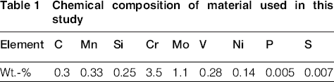
Tool steel with the chemical composition presented in Table 1 was used in this investigation. The specimens were discs, 20 mm in diameter and 10 mm in height. Parallel back and front surfaces of the specimens were ground using SiC paper up to 400 mesh grit. The TRD coating was performed in salt bath containing 15 wt-% low carbon ferrochromium and 85 wt-% borax at 1100°C for 12 h. The TRD and subsequent air quenching treatments were carried out using a procedure similar to austenitisation of tool steel. Afterwards, plasma nitriding was performed at 600°C up to 10 h using a gas mixture of 25 vol.-%H2: 75 vol.-%N2 at a total pressure of 100–500 Pa. Plasma nitriding was used as tempering treatment.
Chemical composition of material used in this study
The samples were examined for the formation of new phases by XRD using a PW 1800 Philips X-ray diffractometer with a Cu Kα radiation. Tapered cross-section of the chromised sample was prepared to observe solid solution and compound layers in one figure and on a large scale. Vega II Tescan scanning electron microscope and optical microscope were used to investigate the surface morphology. Energy dispersive spectroscopy analysis was used to obtain composition profiles in the tapered cross-section. Clemex Version 3.5.025 software was used to measure particles size of nitride phases on the surface of the samples. Vickers microhardness profile was obtained from the vertical cross-section by measuring hardness at different points using SCTMC MHV-1000Z instrument at 0.01 kgf. For this purpose, an average of four readings is calculated for each reported hardness number.
Corrosion behaviour of the specimens was studied by immersing the samples in a 3%NaCl solution for 1000 s. Corrosion assessment was carried out using a three-electrode cell configuration consisting of a saturated calomel reference electrode, a platinum auxiliary electrode and a working electrode (specimen). All potentials were referred to saturated calomel reference electrode. The measurements were carried out using an EG&G 273A computer controlled measurement system. The intersection of cathodic and anodic slope Tafel lines of each curve was used to specify corrosion current densities and corrosion potentials of each sample.
Results and discussion
Structural and phase analysis
Optical micrograph of the surface of the tool steel after TRD treatment is shown in Fig. 1. It is observed that after TRD treatment, carbides are formed on the surface with the same morphology with the substrate. Equiaxed grain structure was observed at the surface of the samples chromised at 1100°C for 12 h. In this image, grain boundaries of carbide phases can be observed on the surface of the samples.
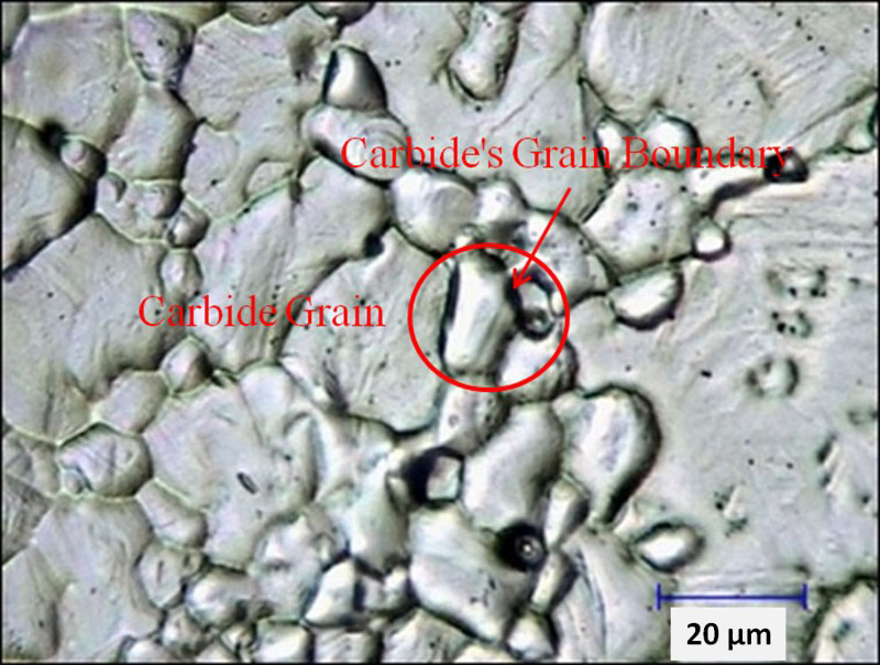
Optical surface microstructure of TRD coated samples in 1100°C, 12 h
Figure 2 shows a tapered cross-section micrograph of the coated layers obtained from TRD treatment and the distribution of Cr, Fe and C elements in the chromised treated area of the tool steel. Distributions of elements are obtained by energy dispersive spectroscopy analysis. It is observed that two distinct layers are formed on the surface of steel after TRD treatment. These layers had relatively flat interphase. Corresponding XRD patterns of the sample shown in Fig. 2 after TRD are illustrated in Fig. 3a.
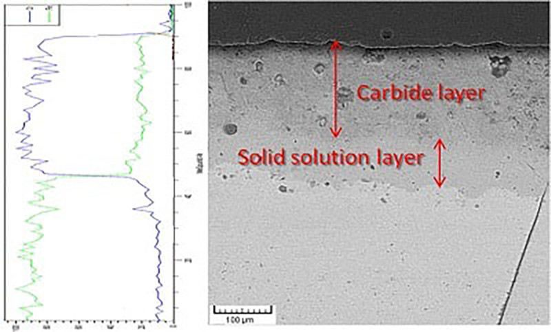
Image (SEM) of tapered cross-section microstructure of TRD chromized at 1100°C for 12 h and line scan analysis along cross-section
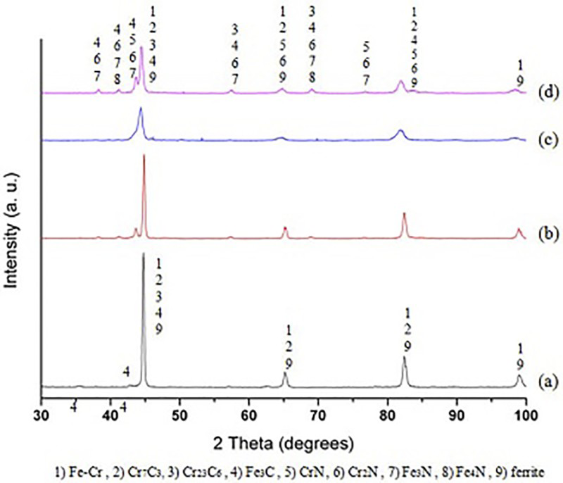
X-ray diffraction patterns of a TRD coated, TRD and CPN at 600°C for b 5 h, c 7.5 h and d 10 h
According to Figs. 2 and 3a, it could be seen that the TRD coatings consist of two layers: (i) top layer, which is mainly composed of chromium carbides such as Cr7C3, Cr23C6 and Fe3C, and (ii) an underneath layer, which is a solid solution of chromium in iron. In addition, the peaks related to iron in XRD patterns are corresponding to the steel matrix. These results are in agreement with other researches. For example, Chang et al. 5 studied chromising of AISI H13 tool steel and reported formation of Fe–Cr ferrite, Cr23C6 and Cr7C3 phases.
Hardness profile of the vertical cross-section of the chromised sample after TRD coating is displayed in Fig. 4. It could be seen that hardness of the substrate increases to 1400 HV0.01 after chromising. This is mainly attributed to the formation of chromium carbides phases (Cr7C3, Cr23C6) in the chromised layer. In addition, solid solution of chromium in iron and some small carbide particles such as chromium and vanadium carbide are in the layer beneath the chromised one, and the hardness of this layer is about 600–1000 HV0.01. These results are in good agreement with previous investigations (e.g. Ref. 15). It is as well seen in Fig. 4 that the thickness of compound and solid solution layers are ∼10 and 25 μm respectively.
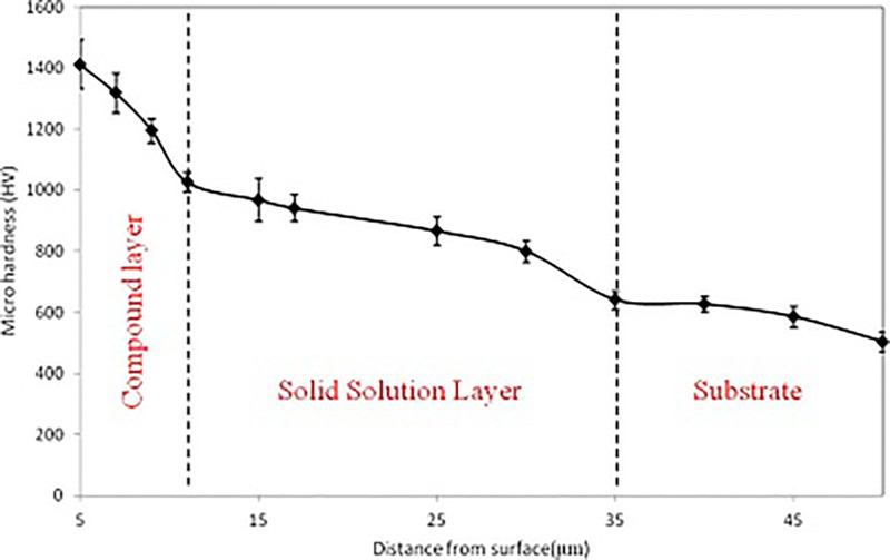
Hardness profile of chromized sample after TRD treatment
After plasma nitriding of TRD coated samples for 5, 7.5 and 10 h at 600°C, the nitride phases form on the surface of the samples. X-ray diffraction patterns of these specimens (Fig. 3b–d) indicate that Cr2N, CrN, Fe3N and Fe4N compounds are formed on the surface, which is in good agreement with the presented results in the literature. 5 During plasma treatment, chromium nitride phases may form on the surface by replacement of carbon of carbides.2,4 Formation of iron nitrides is considered as the consequence of sputtering of the cathode surface and deposition of the sputtered species on the specimen. 19 Moreover, it is seen that the peak intensity of carbide phases decreases with plasma nitriding, which is due to the formation of nitride phases. In addition, with increasing nitriding time, the tendency for the formation of CrN intensifies and its amount increases, which is in agreement with previous investigation. 2 . Furthermore, the quantity of Cr7C3 decreases and that of Cr23C6 increases. This can be correlated to higher stability of Cr23C6 in comparison to Cr7C3 phase.14,26 With increasing time at a constant nitriding temperature, the quantity of iron nitride phases, e.g. Fe3N and Fe4N compounds, increases. 13 In nitriding treatment, nitrogen atoms diffuse into the substrate after deposition on the surface of the sample. Therefore, nitride layers create good bonding with the substrate and improve tribological properties of the surface. 15 After nitriding, it was impossible to observe the nitride layer on the chromium carbide layer in the cross-section of the samples. Since the nitride layer is very thin and brittle, it might be fractured and detached from the beneath layer during metallographic preparation. 19
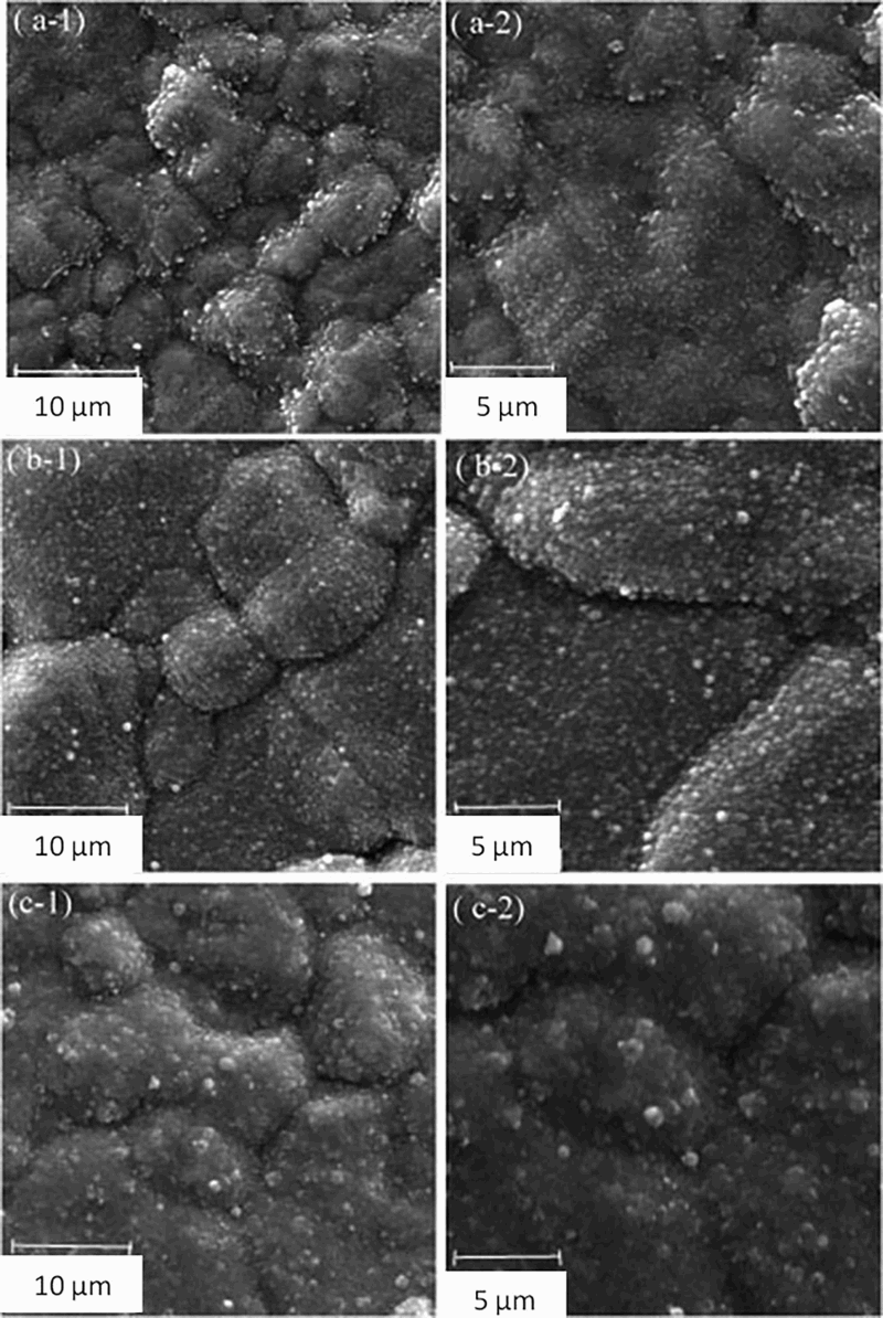
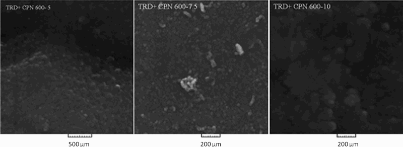
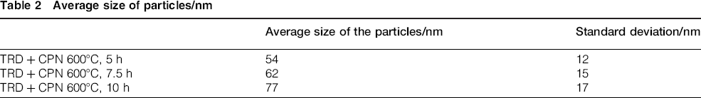
The SEM images of the surface of duplex coatings are shown in Fig. 5. It can be observed that nitride particles with cauliflower morphology have been formed at the surface of chromium carbide grains and on their boundaries. By increasing the nitriding time, the size of nitride particles and the surface coverage of TRD coating increase. According to Fig. 5d, it is seen that at long nitriding time (e.g. 10 h), the grain boundaries of carbides are nearly covered with nitride particles, which is in line with other investigations.2,19,25 This can be correlated to the formation of higher amount of nitride phases with increasing plasma nitriding time.2,13 Fig. 6 shows SEM images from the surface of the samples after plasma nitriding in higher magnification. It is seen that independent of nitriding time, nanoparticulated nitride phases are formed on the surface of TRD coated samples. The size of nitride particles was measured using SEM images and presented in Table 2. It is clear that by increasing nitriding time, size of nitride particles increases. In fact, due to the high ratio of surface to volume of nanoparticles, the tendency of particles for agglomeration is significant.
Secondary electron images (SEM) of surface of TRD and CPN at 600°C for a 5 h, b 7. 5 h and c 10 h
Secondary electron images (SEM) with high magnification of surface of TRD and CPN at 600°C for a 5 h, b 7.5 h and c 10 h
Average size of particles/nm
Corrosion resistance
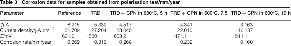
Results of corrosion tests are presented in Fig. 7. Current density, corrosion potential and corrosion rate are extracted from polarisation curves and presented in Table 3. It is observed that by performing TRD and plasma nitriding treatments, current density and corrosion rate of the samples decrease. As a result of the shift in the profiles shown in Fig. 7, similar trend is concluded with increasing plasma nitriding time. The values of corrosion rate of the samples (Table 3) confirm that all of the coated samples indicate higher corrosion resistance in comparison to the untreated steel. This is due to the fact that the chromium and iron nitrides in addition to chromium carbides help to protect the steel substrate against corrosion. 3 From Fig. 7, it can be seen that the current density of reference sample is higher than that of TRD coated one. In addition, by increasing plasma nitriding time, corrosion resistance of duplex treated samples increases, indicated by a decrease in the current density in polarisation test. This improvement in corrosion resistance may be attributed to the formation of higher amount of nitride phases.16,19 Similar results obtained from plasma nitriding of low alloy steel. Ahangarani et al. showed that as nitride is a noble phase,17,27 formation of higher amount of nitride phases decreases corrosion rate. Consequently, with increasing nitriding time or temperature, corrosion resistance of the sample improves. 27 Moreover, from the data presented in Table 3, one may notice that the corrosion rate of duplex treated samples, i.e. TRD and plasma nitriding are less than that of the samples with a single TRD coating. In other words, plasma nitriding of TRD coated samples help to improve the corrosion resistance, which is due to the formation of high corrosion resistance phases, e.g. iron nitrides and chromium nitrides in comparison to chromium carbides. These findings are in agreement with the results of previous investigations. For example, Baggio-Scheid et al. investigated chromising of AISI 1020 followed by plasma nitriding. They found out that anodic current density of samples treated by duplex process is lower in comparison to chromised samples. 3 The values of corrosion rate presented in Fig. 7 confirm that with increasing plasma nitriding time, corrosion rate of samples reduces, which is due to the formation of higher amount of nitride phases 18 and reduction in Cr2N compounds to CrN. This may be correlated to the higher corrosion resistance of CrN in comparison to Cr2N. 14 In addition, with increasing nitriding time, a large fraction of the surface of carbide coating and their boundaries are covered with nitride particles. Since grain boundaries are preferred locations for corrosion, the corrosion resistance of the coating improves with further coverage of the boundaries.
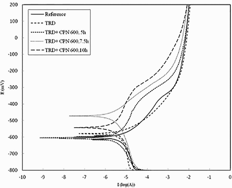
Polarisation curves of specimens
Corrosion data for samples obtained from polarisation test/mm/year
In order to prove the results of corrosion test, the surface of the corroded samples was investigated by SEM. The corroded surfaces of the samples are presented in Fig. 8. The surface of the TRD coated sample after corrosion test (Fig. 8a) is more significantly damaged in comparison to the sample with duplex coating (Fig. 8b). Presumably, it is due to the existence of carbide phases and their grain boundaries that are preferred locations for corrosion. In addition, there are a lot of microcracks in chromium carbide grains. After TRD coating process, there is residual stress in the sample, which is released during the corrosion test leading to the formation of microcracks. It is believed that plasma nitriding plays an important role as a heat treatment step in which residual stresses are relieved. In addition, nitride phases cover their grain boundaries and have more corrosion resistance than chromium carbide phases. Therefore, the surface of duplex treated sample is less damaged than that of TRD coated sample.
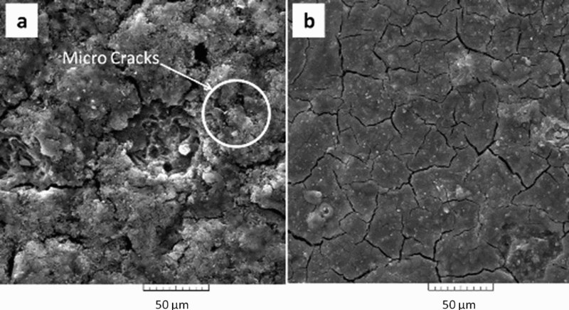
Secondary electron images (SEM) of surface of a TRD and b TRD and CPN at 600°C for 10 h
Conclusion
In this study, the effect of conventional plasma nitriding (CPN) on the properties of chromised tool steel is investigated. Results of this investigation show that chromising by means of TRD method leads to the formation of Cr–Fe solid solution, Cr23C6, Cr7C3 and Fe3C compounds on the surface of the samples, and the hardness of chromised samples increases from 330 to 1400 HV0.01. By post-plasma nitriding for different periods of time at 600°C, a fraction of the Cr7C3 phase is transformed to Cr23C6 and Cr2N, CrN, Fe3N and Fe4N compounds on the surface. In addition, it is found that corrosion resistance of the sample improves with TRD or TRD and plasma nitriding treatment. The corrosion rate of the reference sample decreases from 0.369 to 0.316 mm/year after TRD treatment and to 6.33 mm/year by plasma nitriding for 10 h at 600°C.