
Abstract
The polytypism of SiC, phase transformation of ZrB2 and the interfaces between SiC and ZrB2 were investigated using high resolution TEM in a hot pressed 10 vol.%SiC‐ZrB2 composite. In most cases, no grain boundary interphases between hexagonal ZrB2 and 6H‐SiC phases were observed with SiC being both inter‐ and intragranular. Occasionally, 6H‐SiC transformed into 3C and 15R and hexagonal ZrB2 transformed into cubic ZrB. High resolution TEM showed no grain boundary interphases in most regions. Energy dispersive X‐ray spectroscopy and electron energy‐loss spectroscopy analyses showed the presence of oxygen throughout the sample. The phase transformation of SiC and ZrB2, and the interphase formation between SiC and ZrB2 grains are discussed.
Introduction
The cornerstone of ultrahigh temperature ceramics (UHTC) is a small group of diboride and carbide ceramic–matrix composites including ZrB2–SiC,1–6 HfB2–SiC,7–9 ZrC–SiC,10–12 HfC–SiC,13,14 and ZrB2–SiC–C.15,16 They have a unique set of material properties including unusually high thermal conductivity that makes them particularly well suited for sharp body applications in hypersonic flows.17 However, their use has been limited due to poor fracture toughness,2,3,18–21 moderate thermal shock3,22–25 and oxidation behaviour4,26–30 and inability to make them fully dense. Previous evaluation of these materials suggested that their poor properties were due to agglomerates, inhomogeneities and grain boundary impurities, all of which were believed to be associated with ceramic processing problems.31–34
Among UHTCs, ZrB2 has the lowest theoretical density (6·09 g cm−3), which makes it attractive for aerospace applications.35 Its high melting temperature, good thermal shock and oxidation resistance and relatively low cost when compared with HfB2 based ceramics make it more attractive than other non‐oxide structural ceramics.35 Often, SiC is added to ZrB2 to enhance its oxidation resistance and limit grain growth during densification.33,35–38 Additions of up to 30 vol.%SiC particulates have been found to improve the four‐point bend strength of ZrB2 from ∼565 to ∼1089 MPa and fracture toughness from 3·5 to 5·25 MPa m1/2 by limiting grain growth and promoting crack deflection.39,40
In recent years, significant progress has been made in densification and characterisation of Zr and Hf based UHTCs. Surprisingly, few reports appear in the literature of microstructural defects in grains or at interfaces using transmission electron microscopy (TEM). Therefore, in this paper we report an investigation of phase transformations of SiC and ZrB2 and the interphase formation between ZrB2 and SiC in 10 vol.%SiC–ZrB2 composites sintered by hot pressing.
Experimental
Materials and methods
ZrB2 powder (∼98·5%, d50≈2 μm, 0·2%C, 0·9%O, 0·2%Hf, grade B; HC Starck, Newton, MA, USA) and SiC powder (α‐SiC, 98·5%, d50≈0·7 μm, grade UF‐10; HC Starck) were used as the starting materials. Phase analysis by X‐ray diffraction (XRD) and using selected area electron diffraction (SAED) patterns confirm that both ZrB2 and SiC have a hexagonal structure with lattice parameters of a = 3·17 Å, c = 3·53 Å and a = 3·08 Å, c = 15·12 Å respectively. To reduce particle size and promote intimate mixing, batches of composition 90 vol.‐%ZrB2 and 10 vol.‐%SiC were attrition milled (model 01‐HD; Union Process, Akron, OH, USA). Milled powders were hot pressed (model HP‐3060; Thermal Technology, Santa Rosa, CA, USA) into graphite dies lined with graphite foil and coated with BN. The hot press furnace was heated at an average rate of ∼5°C min−1 to 1900°C at ∼17°C min−1 with simultaneous application of 32 MPa load in flowing argon. After 45 min the sample was cooled at ∼20°C min−1 to room temperature. Each billet is ∼40 mm in diameter and ∼5 mm in thickness. More details of the hot pressing procedure are given by Zimmermann et al.39
Characterisation by TEM
Specimens for TEM observation were prepared from hot pressed materials using conventional mechanical polishing and ion thinning. The ion thinning was performed using a Gatan model 691 precision ion polishing system. Bright field (BF) images and SAED patterns were acquired using a JEOL JEM‐2000EX electron microscope operating at 200 kV. The Burgers vectors
Results and discussion
Figure 1 shows typical BF images of the morphologies of different phases and the interfaces in the composites. Figure 1a clearly reveals small (0·4 μm), intragranular spheroidal SiC grains within (about 2–3 μm sized) ZrB2 grains containing dislocations some of which appear to be associated with the intragranular SiC. Figure 1b reveals an intergranular SiC at a ZrB2 triple junction. The inset SAED pattern is a
 zone axis revealing that the SiC is the 6H polytype. ZrB2 is often observed to have a hexagonal symmetry. The dislocations observed in ZrB2 around SiC in Fig. 1a are most likely caused by thermal expansion mismatch between ZrB2 (P6/mmm) (Ref. 41) and SiC (P63mc) (Ref. 42) grains. Figure 1c–d shows bright field images of a ZrB2 grain in direct contact with a SiC grain. Diffraction contrast imaging of the dislocations in ZrB2 has been performed under two‐beam conditions using different diffraction vectors (
 ). Arrows indicate the direction of
  in Fig. 1c or
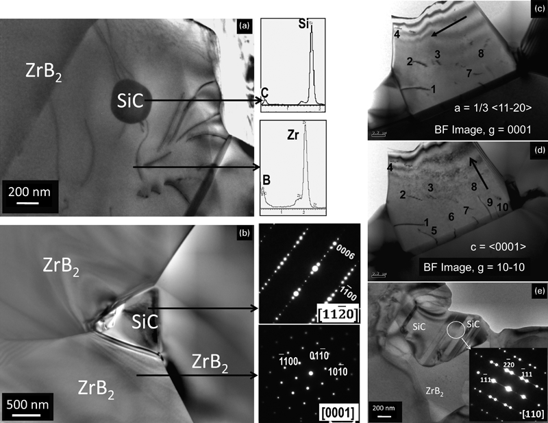
Typical BF images of 10 vol.%SiC‐ZrB2 composite
Grains with similar features are observed throughout the microstructure. Figure 2a shows a typical BF image of a ZrB2/SiC interface. Analysis using EELS (Figs. 2b and c) confirms the striped region A is SiC while region B is ZrB2. Figure 2e shows an HRTEM image taken down the [11
 0] zone axis from the area F in the SiC grain. The SAED pattern obtained from this grain (Fig. 2e) can only be indexed as 15R‐SiC. Careful examination of the SAED pattern reveals streaks between the diffraction spots, which indicate the presence of stacking faults in the 15R‐SiC. The HRTEM image reveals a superlattice structure with c parameter fifteen times that of the 3C‐SiC polymorph. The lattice parameters of 15R‐SiC are determined to be a = 3·06 Å and c = 37·07 Å. As can be seen from Fig. 2d the ideal structure of 15R‐SiC has an ‘ABCACBCABACABCA’ or (3·2)3 sequence.

a BF image of ZrB2/SiC interface, b, c EELS spectra acquired from region B and A respectively, d typical HRTEM image from region A, showing 15R‐SiC polytype, e corresponding
zone axis SAED pattern, f HRTEM image taken from region B, inset showing [0001] zone axis SAED pattern and g HRTEM image of ZrB2/SiC interface
Figure 2f shows a HRTEM image at the [0001] zone axis taken from the area G in the ZrB2 grain. The inset shows the corresponding SAED pattern which can be indexed using the lattice parameters of hexagonal ZrB2. The planar spacings for {10
 0} are measured to be 3·17 Å which matches that of hexagonal ZrB2. Thus, the chemical composition, SAED pattern and the HRTEM image of region B confirm that it is hexagonal ZrB2 which has undergone no phase transformation on processing. SiC is commonly observed in this composite: intragranular (Fig. 1a), intergranular (Fig. 1b) and with faulted contrast (Figs. 1e and 2a). The striped features in the SiC grain are attributed to planar defects such as twins and stacking faults.
High resolution TEM was performed to clarify the nature of the grain boundary between SiC and ZrB2 in Fig. 2a. Figure 2g shows the HRTEM image taken from area C in Fig. 2a around the interface. Figure 2g shows an atomically flat and coherent interface between SiC and ZrB2. It is observed that the grain boundary is clean and does not contain any secondary phases. Furthermore, the region of A in Fig. 2a closer to the SiC/ZrB2 interface shown as 3C in Fig. 2g reveals a 2·49 Å lattice spacing and the atomic arrangements show cubic structure. The lattice parameter is calculated to be a = 4·32 Å from the HRTEM image. Since EELS analysis confirms the presence of only Si and C. This region is confirmed as 3C, i.e., β SiC (a = 4·35 Å). The slightly smaller lattice parameter may be caused by the strain around the interface.
Figure 2g shows two distinct interfaces between 15R‐SiC and 3C‐SiC, 3C‐SiC and hexagonal ZrB2. The crystallographic orientation relationships between these interfaces were determined from Fig. 2g. The crystallographic orientation relationship between 15R‐ and 3C‐SiC is [11
 0]||[110] and (0001)||(111). However, the crystallographic orientation relationship between 3C‐SiC and ZrB2 is [110]||[0001] and (111)||(10
 0). In this orientation, the (10
 0) planes of the hexagonal structure (ZrB2) and the (111) planes of the cubic structure (3C‐SiC) have minimal misfit and the strain can be accommodated more easily. The crystallographic orientation relationships of [11
 0]||[110] and (0001)||(111) are commonly observed for interfaces between a hexagonal and cubic phases.46–48
Figure 3 shows an HRTEM image of a ZrB2/ZrB2 interface in the ZrB2–SiC composite. Grain 2 can be tilted to [01
 1] zone axis perpendicular to (–24–25) plane, while grain 1 cannot be tilted to a low index zone axis. This means that there is no preferential orientation relationship between these two grains. A closer look at the HRTEM image of the ZrB2/ZrB2 interface reveals that no secondary glassy or crystalline interphases are present.
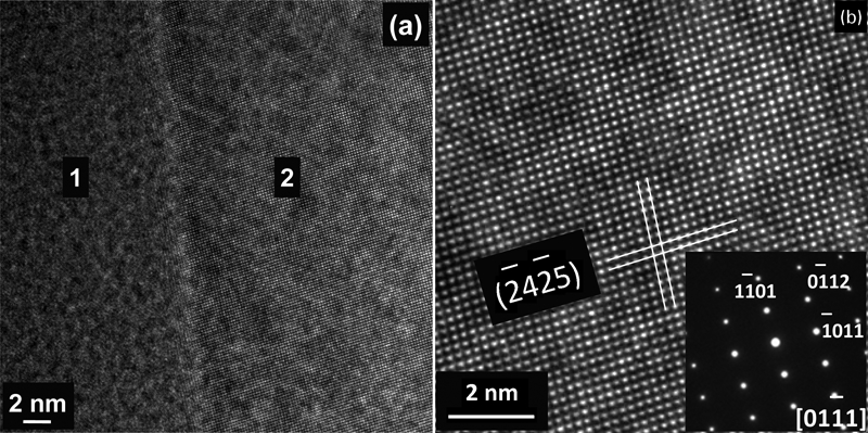
a HRTEM image of ZrB2/ZrB2 interface and b enlarged HRTEM image of grain 2 showing hexagonal structure corresponding to zone axis [0 1 1– 1 ]
Figure 4a shows an HRTEM image of a further interface in the ZrB2–SiC composite. Both grains 1 and 2 can be tilted to respective zone axes which indicates that they have crystallographic orientation relation between them. Although EDS analyses (Fig. 4b) reveal the presence of Zr and B in both grains, quantification of EDS spectra indicates that the composition of these two grains is different. In grain 1 the atomic ratio of Zr/B is close to 1∶2, while in grain 2 the atomic ratio of Zr/B is close to 1∶1. Selected area electron diffraction and HRTEM also confirm the phase differences. Figure 4c shows an enlarged HRTEM image of grain 2. The atomic arrangement clearly reveals it to be a cubic structure with a planar spacing of 2·69 Å for the {111} plane. As ZrB2 is only known to exist in hexagonal form, the existence of ZrB2 is unlikely and also the planar spacing of grain 2 does not match any of the SiC polytypes. In addition, the SAED pattern taken from grain 2 (not shown) can be indexed using a lattice parameter of a cubic phase (4·65 Å). As zirconium boride has another two cubic phases ZrB (a = 4·65 Å) and ZrB12 (a = 7·40 Å), taking into account the EDS quantification results, lattice parameter, and the crystal structure, grain 2 is most likely to be cubic ZrB. This observation suggests that a small amount (perhaps ∼1 vol%) hexagonal ZrB2 transforms into cubic ZrB during the hot pressing.
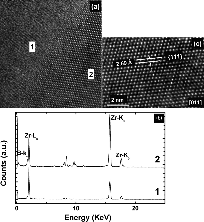
a HRTEM image of ZrB2/ZrB interface, b EDS analyses of grains 1 and 2 and c enlarged HRTEM image of grain 2 showing cubic structure corresponding to [011] zone axis
Figure 5 shows a typical BF and HRTEM image of a three‐grain junction having two interfaces. Grains C and B in Figure 5a have similar contrast while grain A has slightly darker contrast. Grain A occurs as an intergranular phase between the two large grains. Analysis using EDS confirms that the small grain is SiC and the larger grains are ZrB2. Selected area electron diffraction of the large grains reveals that the ZrB2 grains are hexagonal while SAED of the small grain reveals it as 3C‐SiC. Figure 5b shows an HRTEM image of the interface between grain A and grain B revealing a thin 3–6 nm amorphous layer. Analysis of this interphase using EDS reveals Si and O, suggesting an amorphous silica layer forms the interphase at the grain boundary. Although XRD did not detect the presence of oxides or any other secondary phases, EDS and EELS analyses always show the presence of oxygen throughout the sample. The presence of oxygen in the sintered samples is due to its presence in the starting materials.
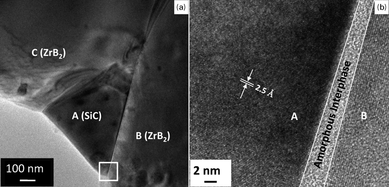
a BF image of three‐grain junction and b HRTEM image of grain boundary interphase taken from square region in a
In this study, uncharacteristic SiC features have been observed including the transformation from α (6H) to β (3C) polytypes. The more usual transformation is β‐ to α‐SiC which is thermodynamically not reversible. Only Kieffer et al.49 have observed 6H‐ to 3C‐SiC transformation in microcrystalline powder at 2800 K when annealed for 4 h in vacuum. An ab initio study on the polytypic transformation suggests that a dislocation mechanism may be responsible for the temperature and deformation induced transitions.50 Calculated energy barriers for 6H→3C make the dislocation mechanism highly favourable for polytypic transformations in SiC.50 The dislocation based polytypic transformation51 results from the strength of the compression applied to 6H during hot pressing. In addition, other impurities such as carbon, silicon or oxygen stabilise the 3C‐SiC structure.52
Another interesting feature is the transformation of ZrB2 into ZrB. Champion et al.46–48,53 studied the Zr/ZrB2 interface and observed ZrB as the grain boundary interphase. Electron diffraction also showed the existence of ZrB cubic phase at the metal/ceramic interface and in some ZrB2 grains. The proposed phase diagram53 also suggested a peritectoid transformation β‐Zr+ZrB2→ZrB occurring between 1200 and 800°C on cooling. By diffusion of boron at the interface and through the peritectoid transformation, the intermediate ZrB phase is created as a buffer between the two low temperature phases preserving the high coherency of the interface. However, in our study, formation of β‐Zr is highly unlikely even though the sintering was carried out in vacuum and hence the formation of ZrB through peritectoid transformation is not possible. In the event of forming a silicate or borosilicate melt during hot pressing, dissolution of ZrB2 in the melt and precipitation of ZrB might be expected. However, the solubility of ZrB2 is low in silicate melts and also the TEM investigation does not show such grain boundary interphase. Therefore the formation of ZrB might be attributed to the following reasons. Although XRD analyses did not show any crystalline oxide phase, EDS always revealed the presence of oxygen. With the presence of any adsorbed oxygen on the surface of SiC, thermodynamically both ZrB2 and SiC will oxidise at high temperatures. It is believed that only boron in ZrB2 receives oxygen forming B2O3 liquid and leaving behind boron‐deficient zirconium boride. This is clearly demonstrated in the EDS analysis in Fig. 4 in that the cubic region contains less boron and more zirconia compared to ZrB2. According to Aronsson,53 in cases where ZrB has been observed, considerable O, C or N was present to stabilise the cubic structure, which is generally assumed to be the ZrB phase. In this study, the presence of impurities such as carbon, silicon and oxygen is most likely responsible for stabilising the formation of ZrB.
Conclusions
High resolution TEM observations reveal that 6H α‐SiC transforms into 3C β‐ and 15R‐SiC and hexagonal ZrB2 transforms into cubic ZrB in some regions of the hot pressed ZrB2–SiC composites. Although these newly formed phases during hot pressing are only present in small amounts, they can significantly influence the high temperature mechanical properties and oxidation behaviour of the composites. The Burgers vectors of the observed dislocations in ZrB2 are determined to be either  or
or
Footnotes
Acknowledgements
One of the authors, DDJ thanks the Defence Science and Technology Laboratory (Dstl) for providing the financial support for this work under contract number DSTLX‐1000015413. The authors kindly acknowledge use of the FEI TITAN 80–300 STEM facility at Imperial College London for HRTEM characterisation of interfaces.