
Abstract
Electrophoretic deposition (EPD) is an attractive forming process to fabricate plate shaped binary functionally graded materials (FGMs) from suitable stable suspensions. In the present work, the capability to produce Al2O3 and ZrO2 functionally graded bulk material by means of EPD from a non‐aqueous stable suspension based on 2‐butanone, n‐butylamine and cellulose nitrate solution is presented. The EPD processing parameters and sintering are described, and the density of the FGM composite, hardness, toughness and residual stresses are measured using indentation methods on cross‐sections of the sample. Scanning electron microscopy confirmed that the sintered body is an FGM.
Introduction
Functionally graded materials (FGMs) are essential for many industries where high hardness, high toughness and high temperature resistance are required. They can be used in microelectronic devices, capacitors, sensors, thermal barrier coatings, etc. A number of manufacturing techniques have been reported for FGM, including chemical vapour deposition, spark plasma sintering, powder stacking and centrifugal casting and electrophoretic deposition (EPD).1,2 Among these processes, EPD can be used to prepare FGM with complex shapes, which reduces the cost and processing time.3,4 Furthermore, continuous production is possible with good control over the hardness and thickness.
The process basically consists of two parts: first, the particles loaded in the suspension are forced with an electric current towards a charged electrode; in the second part, the charged particles are deposited on the electrodes and form a coherent deposit on it.5 The suspensions can be aqueous or non‐aqueous, each of them having advantages and disadvantages.6 Aqueous suspensions are used for EPD basically because of economical and environmental reasons.7 However, the disadvantage of aqueous suspensions is that they create gas bubbles at the electrodes at high voltage.8 Non‐aqueous suspensions can be used for high voltages, high deposition rates and production of complex shaped parts. Their disadvantages are toxicity and their high cost.9,10
For non‐aqueous suspension, acetone has been used to provide zirconia toughened alumina FGM by EPD.11,12 In addition, ketone suspensions have been done for Al2O3 and ZrO2 powders.13 Since EPD depends critically on the rheological and electrical properties of the liquid, it is necessary to study more suspensions and compositions.
In the present paper, a 2‐butanone based suspension is used for EPD and homogeneous as well as functionally graded ceramic–ceramic Al2O3 and ZrO2, where the external layer is Al2O3 and the internal layers are a homogeneous Al2O3 and ZrO2 composite. Mechanical properties were investigated using the Vickers indentation method. In addition, the microstructure of the sintered sample was examined.
Experimental
The starting materials consisted of α‐Al2O3 (99·95%, Alfa Aesar, Ward Hill, MA, USA), with an average crystal and particle size of 0·3 μm, and a partially stabilised ZrO2 powder (5·3 wt‐%Y2O3, Sigma‐Aldrich, St Louis, MO, USA) of submicrometre size. The powders were ball milled in ethanol with zirconium oxide balls (Retch, Haan, Germany) in a horizontal ball mill (9VS, Pascall Engineering, Crawley, UK) for 24 h to break up the hard agglomerates. After mixing, the ethanol was evaporated in an oven (Carbolite, Hope, UK) at 90°C for 48 h. Then, the powders were placed in a drying cabinet for a day. A non‐aqueous medium [2‐butanone, n‐butylamine and cellulose nitrate solution (2% in amyl acetate)] was used. Five different suspensions based on 2‐butanone and n‐butylamine and cellulose nitrate solution were prepared for the EPD process. The suspensions are mixed in a glass container by a magnetic stirrer for 30 min, and then the suspensions were placed in an ultrasonic cleaning bath for 18 min with a frequency of ∼20 kHz.
The EPD cell consists of two stainless steel electrodes. The electrodes have a surface area of 10 cm2 and a thickness of 0·5 cm. The surface of the deposition electrode was polished to facilitate the removal of the deposit and to avoid cracking of the deposit during drying. Furthermore, the edges of the deposition electrode were enclosed by insulation tape in order to avoid deposition around the edges of the electrode. The electrodes were cleaned with acetone and vertically placed in a polytetrafluorethylene (PTFE) vessel. A PTFE vessel was used in order to avoid deposition on the vessel. The container of PTFE has a volume of 100 mL. The distance between the electrodes was fixed at 3 cm. A voltage source, dc power supply (Apparatus Corporation, St Petersburg, FL, USA), was used for applying the electric field. The source was capable of performing either as a constant current or as a constant voltage source. A voltage of 260 V was applied for 30 min. The experimental set‐up for the EPD process is shown in Fig. 1. The suspensions were pumped through the deposition cell by peristaltic pumps. Peristaltic tubing was used for the circulation system, and the diameter of the tubing was 6 mm. The maximum and minimum feedrates were 4·25 and 0·12 mL s−1 respectively. The total deposition time for an FGM was 30 min. A magnetic stirrer was used for mixing of the suspension during all EPD steps.
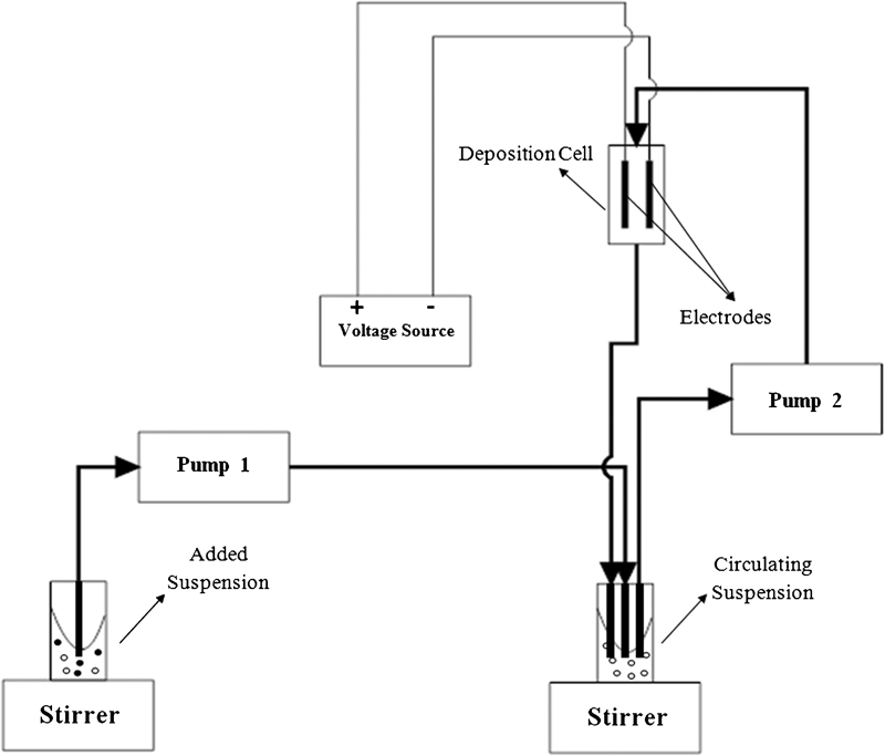
Electrophoretic deposition set‐up
Deposition was started from suspension I, which was poured in the deposition cell, while suspension II with 66·9 g L−1 Al2O3 was added into the beaker of circulating suspension and was pumped through the deposition cell by means of pump 1 at a rate of 2·5 mL s−1. The pump speed rate between deposition cell and circulating suspension was fixed throughout the deposition process. After 300 s of deposition, suspension III, with 172·2 g L−1 Al2O3 and 86 g L−1 ZrO2, was added to the circulating suspension by pump 2 at a rate of 0·4 mL s−1. After 210 s, the addition of this suspension was completed.
During the subsequent step, the suspension was circulated for 800 s without any further additions. Afterwards, 90 mL of suspension IV with 150 g L−1 Al2O3 was added to the circulating suspension by pump 2 at a rate of 2·5 mL s−1 for 280 s. One hundred millilitres of suspension was removed from the circulating suspension by pump 2 at a rate of 1·10 mL s−1, which took 90 s. In the next stage, 100 mL of suspension V with 100 g L−1 Al2O3 was added to the circulating suspension by pump 2 at a rate of 0·8 mL s−1 for 80 s. In the last step, the suspension was circulated between the circulating suspension and deposition cell for 90 s. During all the described steps, EPD was continued in the deposition cell. The powder deposited on the anode. The particles were negatively charged.
After EPD, the deposit was removed from the electrode and slowly dried in a drying cabinet for 24 h under controlled humidity to avoid cracking and non‐uniform shrinkage due to rapid drying. Afterwards, the green body was kept at 100°C for 12 h. The sample was finally sintered for 2 h at 1500°C. To provide time for the binder to burn out, the sample was held at 500°C for 30 min. The sintered cross‐sectioned bulks were ground, polished and thermally etched for 30 min in air at 1350°C for microstructural analysis. The bulk density of the green and sintered bodies was measured using Archimedes’ method. The microstructure of the cross‐section was observed with a scanning electron microscopy (Philips XL30, FEI Company, Hillsboro, OR, USA). X‐ray diffraction analysis (Philips X'pert MPD PW3040, PANanalytical, Almelo, The Netherlands) was performed using Cu Kα radiation.
The Vickers hardness HV5 and HV10 and fracture toughness were measured using a Mitutoyo hardness tester (model AVK‐C2, Mitutoyo, Kawasaki, Japan). From the difference between lengths of cracks parallel and perpendicular to layers, the residual stresses were calculated.
The deposit had a smooth surface and did not crack during drying, as shown in Fig. 2. The thickness of the green deposit was 5·6 mm, and the relative green density of the deposit was 58%, suggesting that the structure of the dry deposit is still open and porous. The obtained sintered density was 4·20 g cm−3. The density of the sample increases when the zirconia content in the compound is increased. The residual porosity can be reduced by increasing the sintering temperature, but this may cause cracks in the sample during sintering as well as undesirable grain growth. The shrinkages of the bulk after sintering expressed as percentage of the initial thickness and length are 12 and 18% respectively.
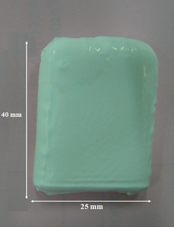
Al2O3 and ZrO2 FGM deposits obtained from suspensions based on 2‐butanone, n‐butylamine and cellulose nitrate solution
Results and discussion
The EDX spectra of the alumina side layer and alumina–zirconia homogeneous layers at the opposite side and the centre of the layered plate are shown in Fig. 3.
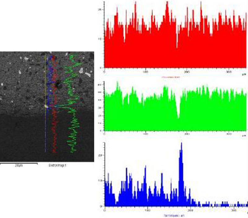
Scanning electron microscopy and EDX at each side of composite: top, oxygen; middle, aluminium; bottom, zirconia
In the alumina layer, only alumina is observed. In The alumina–zirconia layer, a homogenous mixture of 75 vol.‐%Al2O3 and 25 vol.‐%ZrO2 can be seen. Finally, in the outer layer, alumina is increased to 90 vol.‐%. The structure of the FGM is clearly shown in Figs. 3 and 4, where ZrO2 and Al2O3 are shown in white and dark or grey respectively in Fig. 4. The SEM was used to measure the thickness of each layer. The thickness of the inner homogeneous layer was ∼2·5 mm, the outer homogeneous layers were 2·1 mm thick, and the gradient layers were 1 mm.
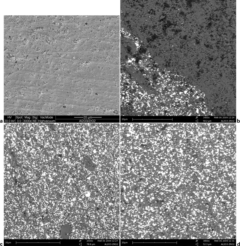
Microstructures of homogeneous layers of FGM
X‐ray diffraction phase analysis cross‐section of the sample at the centre of the homogenous layer is shown in Fig. 5. In the alumina layer, a rhombohedral alumina phase is detected, and in the alumina–zirconia layer, rhombohedral alumina and tetragonal zirconia phases are observed. Therefore, desirable mechanical properties can be expected.
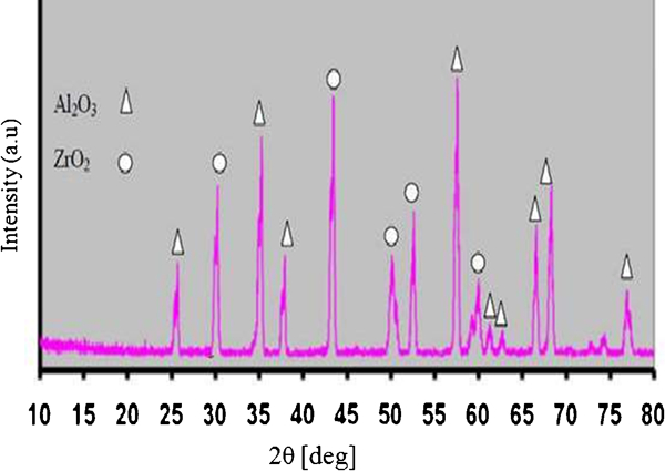
X‐ray diffraction spectra of composite
The concentration gradient is reflected in the mechanical properties of the FGM material, particularly in the Vickers hardness. The HV5 and HV10 hardness profiles measured along the cross‐sectioned FGM material is presented in Fig. 6. The direct correlation between the hardness and the composition profile in the FGM materials is obvious. A decrease in hardness from 22 GPa on the Al2O3 side to 14·75 GPa on the ZrO2 rich side for FGM in the inner layer and then an increase in hardness due to deceasing content of ZrO2 are observed. This is a desired property because a harder surface implies a better contact damage resistance.12 These results are in good agreement with literature data.14 In fact, the hardness of the exterior layers exhibits values more typical for monolithic alumina (18–20 and 17–18 GPa)14–16 that can be attributed to the very dense, fine grained matrix, whose hardness had not been significantly decreased by the zirconia addition.14
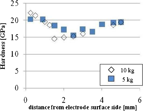
Vickers hardness profile determined on cross‐sectioned FGM for sample measured using different indentation loads
The fracture toughness values were obtained using the Anstis formula,17 with applied indentation loads of 5 and 10 kg respectively.
The results are shown in Fig. 7. The highest fracture toughness value found was 6·5 MPa m1/2, while the lowest value was 2·6 MPa m1/2. The literature data for homogeneous Al2O3 and ZrO2 composites range from 4 to 5 MPa m1/2 depending on the grain size.15,16 In this study, the results are a little lower, only the central part containing 25 vol.‐%ZrO2 is tougher. This shows that the fracture toughness values had increased due to the increase in zirconia content in the composite. The load can affect the indentation size and the crack length, both being dependent on the sample dimension and microstructure of the material. The load for the measurement should be chosen high enough so that variation in the load does not lead to difference in measured hardness.18 The solution is that measurement of the Vickers hardness be carried out in raised loads,19 where the influence of the load in the measurement of the hardness decreases and so the standard hardness can be obtained.
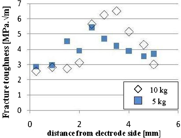
Indentation fracture toughness
The residual stresses were calculated from the indentation cracks and according to Ansist formula12,17 and are shown Fig. 8. The indentation loads were 5 and 10 kg respectively. The exterior layers were subjected to compressive stresses of ∼150 MPa, while in the interior layer, tension with the maximum of ∼250 MPa was found. It is observed that there are advantages of having the surface of the outer layers in compression and in the inner layer in tensile. Therefore, the compression stress in the surface layer slows crack growth and thereby increases wear resistance. The gradient transition between the outer and inner layers prevents interfacial stresses. It was impossible to produce them with the present geometry because the samples disintegrated during cooling12 and also polishing; grinding and indenting inclination can affect the measurement of residual stresses value. Overall, the mechanical properties were found to be very similar to those obtained acetone based suspension,11,12 despite a slight difference in the material used.
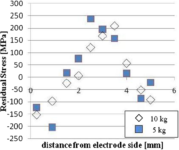
Residual stresses measured by indentation method
Conclusions
This study uses a procedure that was described for the manufacturing of Al2O3 and ZrO2 composite plates with an exterior layer of pure Al2O3, a central homogeneous Al2O3 and ZrO2 composite layer and intermediate continuously graded layers, where the FGMs were prepared by means of EPD from a stable suspension based on 2‐butanone with combined addition of 10 vol.‐% n‐butylamine and 1 vol.‐% cellulose nitrate solution. The hardness, fracture toughness and residual stresses were measured by indentation methods on the cross‐section of the sample. Their changes with respect to the compositional profile were identified. The material exhibited excellent hardness in the outer layers, comparable to that of pure alumina.
Recommendation
This study focused on the production of Al2O3 and ZrO2 FGM by EPD. The non‐aqueous suspensions are popular media and have been used in this research for EPD. However, development of aqueous EPD will go a long way in reducing cost of deposition and also in minimising environmental concerns associated with the use of non‐aqueous suspensions.
Footnotes
Acknowledgements
This work has been financially supported by the University of Malaya (Kuala Lumpur, Malaysia), under grant no. P0051‐2008B. The authors are grateful for the grants.