
Abstract
Due Owing to the presence of metallizations on their surface, the property requirements for dielectric loaded antennas (DLAs; quality factor Qf0 of >5000 GHz and temperature coefficient of resonant frequency of −40<τf<+40 MK−1) are less stringent than for cavity filters (Qf0 of >30 000 GHz, τf = ±1 MK−1 and relative permittivity of 20<ϵr<50). ϵr, however, should be as high as possible to decrease the component size and raw materials, and the energy production costs must be minimised since the DLAs are incorporated into the mobile handsets. In the present work, the use of in-house glass (BN1, 30Bi2O3–30Nb2O5–30B2O3–10SiO2, mol.-%) as an aid to reduce the sintering temperature of barium neodymium titanate (BNT, Ba4Nd9·33Ti18O54) ceramics is studied. The addition of 10 wt-% BN1 glass to BNT (BNT-10BN1) resulted in a 150°C decrease in sintering temperature of BNT. However, the glass reacted with the BNT ceramic and formed an unknown pyrochlore structured phase, which resulted in a decrease in ϵr from ∼80 to ∼73, Qf0 from 8400 to 2800 GHz and τf from ∼65 to 40 MK−1. ϵr, Q and τf further decreased when 20 wt-% BN1 glass was added to BNT ceramics. Despite the reduction in material properties, BNT-10BN1 was still considered suitable for DLA applications.
Introduction
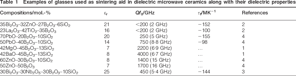
Many different types of glasses (Table 1) have been studied and commercialised as sintering aids in applications such as low temperature cofired ceramics.1–4 In general, glasses possess lower relative permittivity ϵr and quality factor (Q≈1/dielectric loss) compared to their ceramic counterparts. They also have a large negative temperature coefficient of resonant frequency τf.4 In contrast, microwave applications require high ϵr for miniaturisation, a high Q to improve the selectivity to frequency and a low τf to engender stability of the device under various environmental conditions.5 The addition of glasses to ceramics invariably degrades ϵr and Q, but there is huge interest in academia and industry to minimise the deterioration by improving the glass composition. However, as illustrated in Table 1, increasing the permittivity by incorporating highly polarisable cations, such as Nb, Ti, Pb and Bi, results in materials with a much larger negative τf and a lower Q.4
Examples of glasses used as sintering aid in dielectric microwave ceramics along with their dielectric properties
In recent years, new applications have emerged for microwave ceramics with the development of hand held satellite navigation devices and phones, which require antennas with higher gain to deal with the low power signals from satellites in geostationary orbit. Improved efficiency is attained by loading the antenna with a high permittivity medium, the so called dielectric loaded antenna (DLA). 3 3,6 The two most common designs are the ubiquitous microstrip patch antenna and the more expensive yet superior quadrifilar helix (Fig. 1).
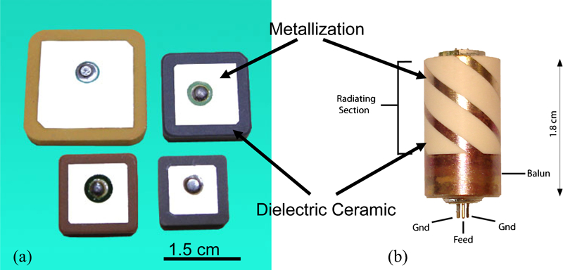
Common designs for a microstrip patch and b quadrifilar helix antennas
The current generation of DLAs, however, uses materials originally fabricated for use as cavity filters and resonators in cellular base stations. The latter application has stringent material property requirements, quality factor Qf0 of >30 000, τf = ±1 MK−1 and relative permittivity of 20<ϵr<50 and invariably require a high sintering temperature (>1400°C), which adds greatly to production costs. In DLAs, ceramics are coated with metallisation in bespoke patterns. However, the presence of metallisation reduces the Q of the device with respect to that of the ceramic, and therefore, the material requirement for dielectric loss can be relaxed with respect to those of cavity filters. A further result of the lower Q for the device is that the requirements for τf of the dielectric may be relaxed and materials with larger values of τf may be utilised in such devices.
Zirconium titanate stannate (ϵr = 38) and barium neodymium titanate (BNT, ϵr = 80) are two of the most common ceramics currently used in DLAs. These materials possess high Qf0 of >8000 and close to zero τf but a sintering temperature of >1350°C. These ceramics are therefore ideal candidates for the incorporation of sintering aids to lower temperature, thereby significantly decreasing production costs and carbon emission.
Recently, the authors have developed a new glass system based on Bi2O3–Nb2O5, which, when crystallised at 960°C, has ϵr≈15, Qfo≈15 000 GHz and τf≈−70 MK−1.3 The addition of this glass to bismuth niobate ceramics resulted in samples with promising microwave dielectric properties (ϵr = 38, Qfo≈17 300 GHz and τf≈−10 MK−1).7 In the present work, the effect of the addition of this glass to BNT ceramics is studied with the aim of fabricating a low sintering temperature glass–ceramic composite suitable for DLA applications.
Experimental
30Bi2O3–30Nb2O5–30B2O3–10SiO2 (mol.-%) glasses were prepared using a conventional glass melting route. Bi2O3, Nb2O5 and H3BO3 in reagent forms and sand (>99·5%SiO2) were weighed out and dry milled for 2 h in a ball mill with ZrO2 media to ensure mixing. Batches were then melted in covered alumina crucibles at 1250°C for 2 h and eventually cast into distilled water to make frit. Owing to the excessive reaction of the melt with Pt crucibles, all the melts were conducted in alumina crucibles.
To synthesise Ba4Nd9·33Ti18O54 (BNT) powder, BaCO3, Nd2O3 and TiO2 in reagent forms (>99% purity) were weighed out in appropriate ratios and ball milled for 24 h in ethanol in plastic jars using Y stabilised zirconia media. The resulting slurries were then dried and sieved before calcination at 1150°C for 4 h. The glass frit was also ball milled and dried using the same conditions. Batches based on 10 wt-% (BNT-10BN1) and 20 wt-% (BNT-20BN1) glass powders were then prepared by mixing the calcined BNT powder and the milled glass frit. The resulting mixtures were remilled and dried using the same conditions, followed by pressing into pellets (10 mm diameter and 5–6 mm thickness) and sintering at 1350, 1200 and 1100°C for BNT, BNT-10BN1 and BNT-20BN1 respectively. All the sintered samples had a density of >94% of their theoretical density. For microstructural analysis, the BNT samples were polished and thermally etched at 1250°C for 1 h. To avoid Bi loss, the BNT-10BN1 and BNT-20BN1 samples were only examined in the as polished state. All the samples were carbon coated before examination under a JEOL 6400 scanning electron microscope (SEM). A Philips Tecnai transmission electron microscope (TEM) was used for further microstructural analysis. Samples for TEM were ground to ∼30 μm before ion thinning in a Gatan duo mill. A Solartron 1260a impedance analyser (Farnborough, UK) was used to study the dielectric properties from 20 Hz to 1 MHz at 20–700°C with 25°C intervals.
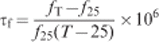
ϵr was measured at microwave frequencies on samples of 8 mm in diameter and 4–5 mm in thickness using the post-resonator method, as suggested by Hakki and Coleman,8 and modified by Courtney9 and an R3767CH-8 GHz Advantest Vector Network Analyser. Q was measured using transmission resonant cavity technique with a gold coated brass cavity and fused silica support. The temperature coefficient of the resonant frequency τf was determined for at least five temperatures between 25 and 80°C using
Results and discussion
Phase and microstructural analysis
The addition of 10 and 20 wt-% BN1 to BNT reduced the sintering temperature required to achieve >94% theoretical density from 1350 to 1200 and 1100°C respectively. Figure 2 shows the XRD traces of BNT, BNT-10BN1 and BNT-20BN1. The major phase in all the samples could be indexed according to BaO–Nd2O5–5TiO2 (International Centre for Diffraction Data, 36-166). Peaks associated with a secondary phase were additionally observed when 10 wt-% BN1 glass was added to BNT, but no International Centre for Diffraction Data card was found to adequately match its d-spacings. However, the distributions of intensities of the second phase peaks were similar to those of cubic (Fd3m) pyrochlore structured compounds. Pyrochlore structured compounds have the general formula A2B2O7, in which the A cation radius is typically ⩾1 Å and the B cation is between 0·6 and 0·8 Å. Within the pyrochlore structure, Bi and Nd ions are therefore likely to occupy the A sites and Ti and Nb ions the B sites.
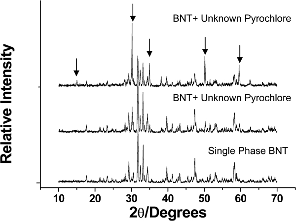
X-ray diffraction traces of BNT, BNT-10BN1 and BNT-20BN1: arrows indicate peaks associated with unknown pyrochlore phase
In BNT-20BN1, the intensity of peaks associated with BNT reduced considerably, coincident with an increase in the intensity of the peaks ascribed to the pyrochlore phase and indicating that BNT and BN1 react. BN1 glass, when heat treated at >900°C, undergoes volume crystallisation to form BiNbO4.3 However, this phase could not be identified in the XRD traces of BNT-10BN1 and BNT-20BN1, adding yet further evidence to the premise that BN1 and BNT react to form the pyrochlore phase.
Figure 3 is a secondary electron image of a polished, thermally etched BNT sample, which reveals a dense microstructure comprising BNT grains of 5–10 μm length and 1–2 μm width. Figure 4a and b shows the secondary electron image and backscattered image of a polished BNT-10BN1 sample. The backscattered image revealed grains of darker contrast in which a brighter contrast phase was dispersed. Energy dispersive spectroscopy (EDS) traces of the former (Fig. 4c) showed that they contained Ba, Ti and Nd, consistent with BNT. The EDS traces taken from the brighter contrast grains (Fig. 4d) showed a substantially larger concentration of Bi and Nb compared to BNT and presumably correspond to the pyrochlore phase, whose peaks are present in the XRD traces (Fig. 2).
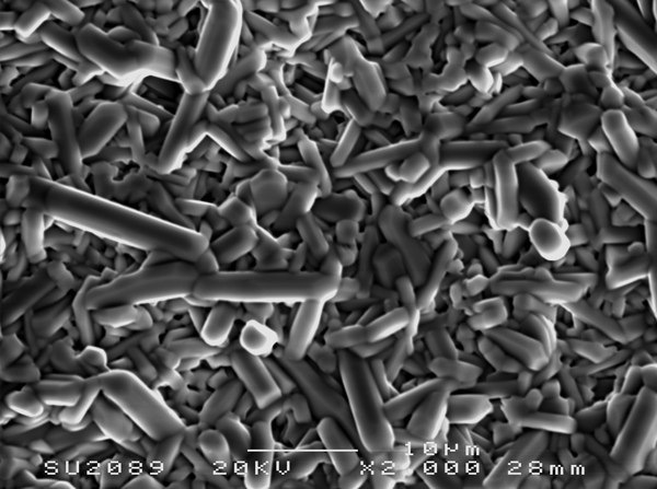
Secondary electron SEM image of polished and thermally etched BNT sample revealing lath shape Ba4Nd9·33Ti18O54 grains
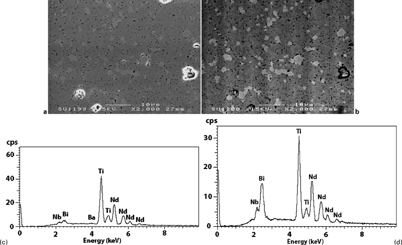
a secondary electron SEM image of polished BNT-10BN1 sample along with its relevant b backscattered electron SEM image and c, d EDS traces of darker and brighter contrast grains in b respectively
In the BNT-20BN1 samples, however, three regions of different contrasts were observed (Fig. 5a and b). The EDS traces of the bright and intermediate contrast grains were similar to Fig. 4c and d respectively and consistent with BNT and the unknown pyrochlore phase. The darkest contrast regions were rich in Al and Si. Only two phases were identified in the XRD trace, and it is therefore likely that the darker contrast regions arise from an aluminoborosilicate glass phase. According to the X-ray fluorescence data presented by Mirsaneh et al.,3 BN1 glass contains up to 10 mol.-%Al2O3 contamination from the dissolution of the alumina crucible in which the glass melts were prepared.
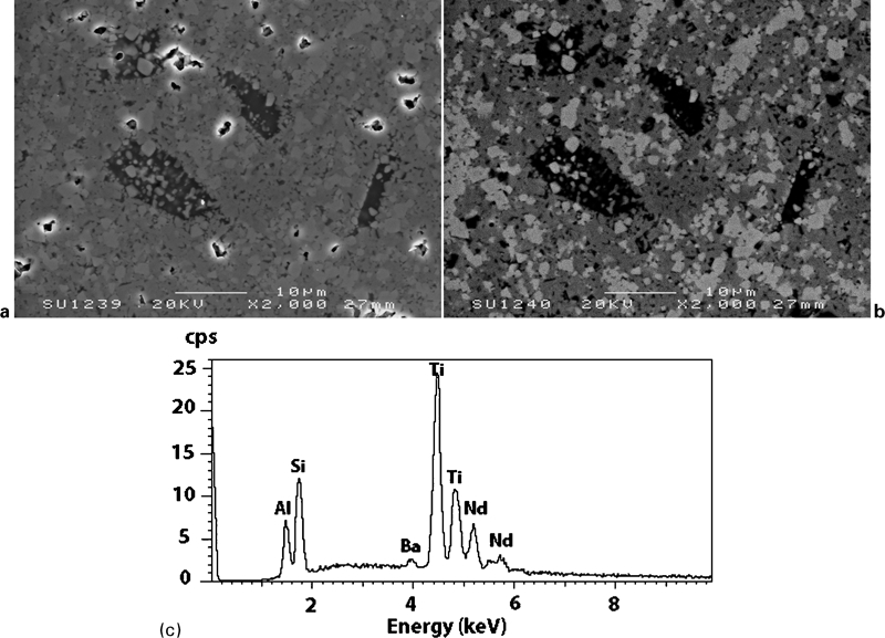
a secondary electron SEM image of polished BNT-20BN1 sample along with its relevant b backscattered electron SEM image and c EDS trace of darkest contrast regions in b
The TEM images of BNT-10BN1 revealed a residual glass phase at the triple grain boundaries of the BNT matrix (Fig. 6b), and similar images were obtained from the BNT-20BN1 samples (Fig. 7a). Although the regions of the glass were more abundant in BNT-20BN1 compared to that in BNT-10BN1, they had similar composition (Al and Si rich) to those observed in BNT-10BN1 (Fig. 7d), consistent with the EDS data from the dark contrast regions in Fig. 5a and b. As anticipated, the majority of grains in BNT-10BN1 and BNT-20BN1 were BNT (Fig. 7b). However, some grains in BNT-10BN1, e.g. Fig. 6b, and BNT-20BN1 contained Bi and Nb (Fig. 7c), in agreement with the EDS data from the bright contrast phase in the SEM images shown in Fig. 5b and c respectively. Figure 8 shows the 〈100〉 and 〈110〉 zone axis electron diffraction patterns obtained at the same camera length from the Bi and Nb rich phases. The patterns are readily ascribed to a generic face centred cubic structure, but the reflection conditions in the 〈100〉 zone axis indicate that for {00l}, l = 4n, and for {0kl}, k, l = 2n but k+l = 4n. The absence of reflections of the type {00l}, l = 2n and 2n+1, and {0kl}, k+l = 2n, indicates that the structure has an Fd3m symmetry. In Fig. 8b, reflections of the type {00l}, l = 2n, appear due to the generic double diffraction route

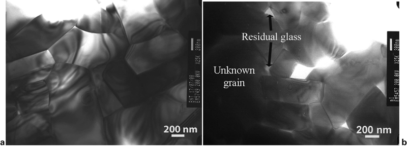
Bright field TEM image of a BNT ceramic along with b BNT-10BN1
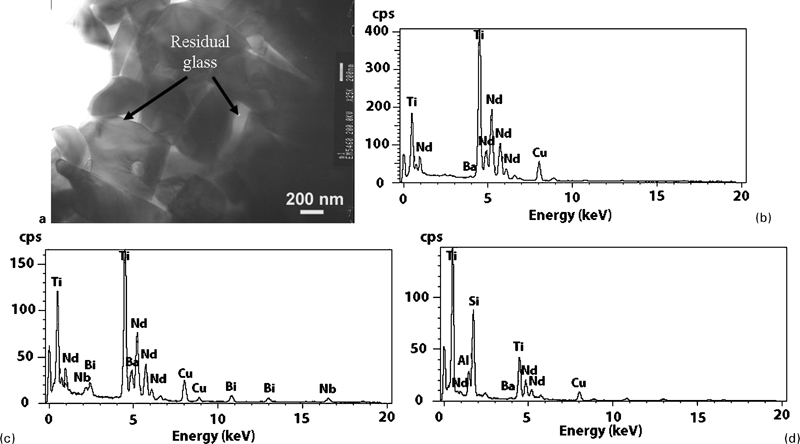
a bright field TEM image of BNT-20BN1 along with EDS traces of b BNT grains, c pyrochlore and d residual glass
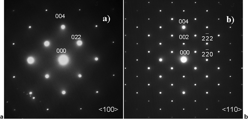
a 〈100〉 and b 〈110〉 selected area zone axis diffraction patterns from unknown pyrochlore phase shown in Fig. 6a
Alternating current impedance analysis
The data obtained by XRD, TEM and SEM/EDX, as discussed earlier, confirmed that the BNT sample is single phase, in contrast to BNT-10BN1 and BNT-20BN1, which were composed of BNT, an unknown pyrochlore phase and a residual glass phase. The dielectric properties of the BNT phase have been frequently reported, e.g. by Morrison et al.,10 but those of the pyrochlore and residual glass phases are unknown, and therefore, it is difficult to predict their effect on dielectric properties in the BNT-10BN1 and BNT-20BN1 samples. To further study the effect of pyrochlore/residual glass on the dielectric properties, impedance spectroscopy was undertaken. Figure 9a shows the imaginary parts of impedance Z″ and electrical modulus M″ for BNT, BNT-10BN1 and BNT-20BN1 at 600°C, revealing the presence of a single peak for all the samples. In Z″ and M″ versus frequency plots, the peak maximum is proportional to R and C−1 (where R is the resistance, and C is the capacitance) respectively.10 Therefore, the former highlights the component with the highest resistance and the latter with the lowest capacitance. In Fig. 9a, Z″ and M″ peaks occur almost at the same frequency for each sample, indicating that both are associated with the same component. This is common in single phase systems, where two parallel RC elements (grain and grain boundary) are in series, and when the capacitance of grains is two to three orders of magnitude smaller than the grain boundaries.11 Because of their multiphase nature, it was expected that the equivalent electrical circuits for BNT-10BN1 and BNT-20BN1 would include multiple parallel RC elements related to each phase. However, the presence of just a single RC element in Fig. 9a could be due to the considerable difference in the electrical resistance of the phases present, rendering the more capacitive elements (presumably pyrochlore and glass phases) inactive in the ac impedance response. Assuming that the electrical components observed in Fig. 9a correspond to the BNT related phase for all the samples, the frequency shift of the Z″ and M″ peak positions for different samples demonstrates that these components have different time constants. This is an indication that the composition of the main phase changes with the addition of glass, as suggested by EDS. Figure 9b shows the Arrhenius plots at about 400–700°C, revealing the activation energy for conduction of the phases present in Fig. 9a. Single phase BNT samples gave an activation energy of 1·17 eV. The activation energy for the grains in BNT-10BN1 was 1·16 eV, a further indication that the component present in Fig. 9a was associated with BNT grains rather than pyrochlore or residual glass. However, Fig. 9a illustrates that the resistance of BNT grains in BNT-10BN1 was slightly higher than those within the BNT sample. Table 2 shows the EDS semiquantitative analysis of various phases in the samples, revealing that the BNT grains in BNT-10BN1 contained small but clear traces of Bi and Nb. If Nb5+ substitutes for Ti4+ within the BNT lattice, then it is likely to act as donor dopant, which typically increases the dc resistance.12
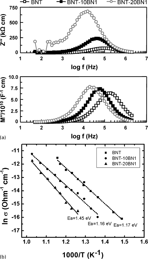
a imaginary part of impedance Z″ and electrical modulus M″ versus log frequency at 600°C for BNT, BNT-10BN1 and BNT-20BN1 samples and b Arrhenius plots corresponding to components revealed in a
Semiquantitative chemical analysis of various phases in BNT, BNT-10BN1 and BNT-20BN1 as revealed by EDS
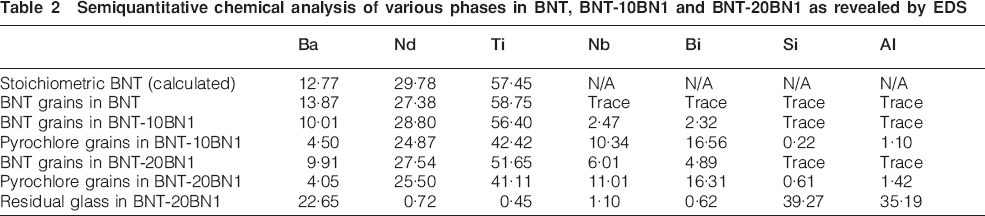
In BNT-20BN1, the activation energy of the BNT phase (1·45 eV) is much higher than that of BNT (1·17 eV) and BNT-10BN1 (1·16 eV). It is likely therefore that increasing the fraction of BN1 glass added has resulted in further modification of the BNT matrix composition. This premise is supported by the EDX data presented in Table 2, which reveals a higher concentration of Nb and Bi in the BNT grains.
Microwave dielectric properties
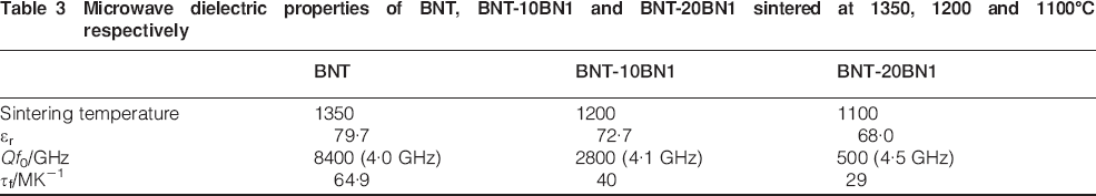
Table 3 presents the microwave dielectric properties (ϵr, Qf0 and τf) of BNT, BNT-10BN1 and BNT-20BN1 BNT-20BN1. ϵr decreased from 79·7 to 68·0 when 20 wt-% BN1 glass was added to BNT, and Qf0 and τf decreased from 8400 to 500 and from 64·9 to 29 MK−1 respectively. The XRD, SEM and TEM data showed that BNT-10BN1 and BNT-20BN1 were composed of BNT, a pyrochlore phase and a glass phase. To account for the improvement in temperature stability of the composite, the pyrochlore and/or glass phase must have a lower τf than the BNT matrix. Following the same logic, the pyrochlore and glass phases must also have lower permittivities than BNT. The decrease in Q may also arise from the presence of a glass and pyrochlore phase, which has a higher dielectric loss at microwave frequencies than BNT. However, the interfaces between the various phases may also contribute to the lower Q since these are sources of disorder, which are detrimental to dielectric loss.13 Despite the reduction in properties associated with using BN1 as a sintering aid in BNT, BNT-10BN1 still has potential for use in low cost DLAs.
Microwave dielectric properties of BNT, BNT-10BN1 and BNT-20BN1 sintered at 1350, 1200 and 1100°C respectively
Conclusion
The addition of 10 wt-% BN1 glass to BNT reduced the sintering temperature by 150°C but resulted in a decrease in ϵr and Qf0 from ∼80 and ∼8400 to ∼73 and ∼2800 respectively. τf also decreased from ∼65 to 40 MK−1. The addition of 20 wt-% BN1 to BNT further reduced the sintering temperature but resulted in a significant deterioration of Q and ϵr although τf improved. The deterioration of ϵr and Q was attributed to the presence of a pyrochlore structured secondary phase along with an alumina borosilicate residual glass phase. The pyrochlore phase was present due to the reaction between the glass and BNT phase. Alternating current impedance spectroscopy and semiquantitative EDX revealed that the BNT grains were doped with Nb and Bi, resulting in an increase in electrical resistance. It was, however, impossible to characterise the electrical properties of the unknown pyrochlore and the residual glass phase, due to their highly capacitive nature compared with BNT grains. Although the properties of BNT-10BN1 are not suitable for resonator applications, which require close to zero τf (±1 MK−1) and large Qf0 (>30 000),5 they meet the desired specifications for DLAs, and its lower sintering temperature reduces the energy cost associated with production.
Footnotes
Acknowledgements
The authors are grateful to Professor D. Sinclair for valuable comments on the impedance spectroscopy data.