
Abstract
The production of synthesis gas from renewable fuels is an emerging technology. The aggressive process environment in fuel production systems poses a major challenge, potentially causing corrosion within currently used metallic heat exchangers. To improve the reliability and stability of silicon carbide heat pipes, which belong to an innovative heat exchanger design, the corrosion of involved materials due to contact with steam, ash and alkaline (earth) metals needs to be investigated. Exposures of laser joined SSiC connections with wood ash caused the formation of gas inclusions and an infiltration of the joint with alkaline (earth) metals that lead to crack formations, as revealed by energy dispersive X-ray spectroscopy analysis. It was shown that the use of silicon carbide heat pipes joined with solder materials of both the Mg–Al–Si and the Y–Al–Si systems is possible. A further result was that the gasification temperature has to be limited to < 850°C.
Introduction
Modern gasification power generation systems are an efficiently and ecologically working alternative to conventional power generation systems. Especially, the fabrication of synthesis gas from biomass resources is a next generation technology. Both liquefaction and thermochemical gasification are commonly used processes to produce chemical precursors from coal and biomass. 1 For thermochemical synthesis gas production, a variety of methods can be used. 2 One of the most efficient biomass gasification technologies is the fast internally circulating fluidised bed gasification (Güssing, Austria). This gasifier generates synthesis raw gas at temperatures of >900°C. For further process steps, the gas needs to be cooled down by reliable heat exchangers.
Utilised in a gasifier, heat exchangers are required to withstand high temperatures and a reducing water vapour and alkali rich atmosphere. The composition of the gas and solid phases, which are released from the gasifier, depends on the process operating temperature, pressure, fed fuel and oxygen content. More specifically, in a reducing environment, H2, CO, CH4, H2O, N2 and CO2 are the major gas constituents. Sulphur is released as H2S and COS, and chlorides are emitted as volatile HCl and alkali chlorides. The concentration of the gaseous sulphur, chlorine and alkaline metal species, released from the gasifier, is both feed and process operating parameter dependent. Unlike combustion systems, alkali species are projected to remain as alkali chloride phases as the gas passes through the gasification system. 3
At the same time, heat recovery should occur at high working temperatures in order to increase the overall process efficiency. This fact also leads to high thermal and corrosive stresses on the structural heat exchanger materials.
Li et al. 4 provide an overview on the currently most commonly used heat exchangers, as variations of plate and shell and tube heat exchangers combining ceramic and metal components. Pure metal heat exchangers show clear limitations in terms of the process temperatures and corrosive conditions they can be used in. The application of ceramic components with high thermal stability, low raw material costs and outstanding corrosion resistance can increase the efficiency of the plant. The development of ceramic plate heat exchangers is described by Schulte-Fischedick et al. 5 and Peterson et al., 6 both using tailored SiC ceramics as structural materials. The required joints between the individual structural parts were produced using ceramic suspensions or infiltration techniques with the disadvantage that several high temperature sintering processes are required to achieve the final joint strength.
Another technical solution for heat recuperation is the use of heat pipes. The working principle of such a heat pipe is described by Grover et al. 7 According to Stumpf, 8 heat pipes have significant advantages to conventional plate and shell and tube heat exchangers; examples include adjustable size, operation unaffected by failure of neighbouring units and ease of cleaning. A major factor contributing to this is the relative ease of sealing of the heat pipe recuperation during integration into the overall system in comparison with the more difficult connection of a shell and tube heat exchanger unit. Efficiency of heat recuperation is higher compared to other ceramic heat exchanger designs. 8 This applies to both thermodynamic and economic aspects. Nevertheless, there are still deficiencies in material development and fabrication of these heat exchanger units. Karellas et al. 9 performed further work with similar heat pipe systems; these consisted of a metallic liner inside the ceramic sleeve.
Possible joining technologies for producing bonded joints between ceramic components are described by Fernie et al. 10 Selection of a suitable joining process for ceramic components of defined geometry is based on numerous factors, including the ionic/covalent bond character and the low diffusivity of the ceramics to be joined. A common selection process involves direct comparison of selected joining methods. Characteristics of seams made of the same materials but prepared using different methods are compared and evaluated. 11 The hermetically sealing of the ceramic heat pipe's two parts (ceramic tube and end cap) is the most critical step in their manufacturing. Because the ceramic tube is filled with the working fluid before sealing, it is necessary that the brazing process fulfils two conditions: first, brazing temperature has to be higher than the planned application temperature of the heat pipes, and second, the inserted working fluid should not change into the vapour phase before the connection between the ceramic tube and the end cape was achieved. On the basis of these assumptions, the theoretical possibilities become more and more limited. One proven method for preparing bonded joints between ceramic components, and which fulfils both of these conditions at the same time, is laser joining. With a laser joining technology, it is possible to heat only local the joining zone. To enable uniform heating of the joint area, the seam has to be centred in the laser beam. 12 In previous studies, it was proven that laser radiation at high temperatures could produce joints of high durability, tightness and mechanical strength.13–15
The ceramic material, i.e. sintered silicon carbide SSiC, was selected on the basis of compatibility of the tested filler systems and its interaction against zinc as planned working fluid. Recent research work has shown that SSiC is stable and does not react with the molten zinc. 16
Most promising is the use of glass filler systems. 17 Especially, silicate glasses of the systems Y2O3–SiO2, Y2O3–Al2O3–SiO2, MgO–Al2O3–SiO2 and MgO–BaO–SiO2 show suitable thermodynamical behaviour for laser joining processes.18–21
In the present work, the reliability of laser joined silicon carbide heat pipes in a gasification-like atmosphere was studied. In particular, four different types of silicate glass filler systems were investigated. The samples were exposed to a gasifier-like atmosphere at temperatures between 800°C and 900°C for the time period of 250 h. Corrosion effects after exposure were analysed by scanning electron microscopy (SEM) and energy dispersive X-ray spectroscopy (EDX). Recently, the corrosion behaviour of ceramic filter candle materials and several refractory materials was investigated under similar conditions,22,23 which can also indicate suitable glass filler systems.
Experimental
The material selected for the ceramic heat pipes was a densely sintered silicon carbide (‘S-SiC’, FCT Hartbearbeitung GmbH, Sonneberg, Germany) with a flexural strength of 450 MPa (20–1000°C), a thermal conductivity of 125 W (m K)–1 (20°C) and a thermal expansion coefficient of 4·5 × 10–6 K–1 (20–1000°C).
For the laser joining of the SSiC ceramics, a diode laser from ROFIN-SINAR Laser GmbH (Hamburg, Germany) with wavelengths of 808 and 940 nm and a peak power of 3·1 kW was used. For the uniform heating of the joint area, the parts to be joined were rotated during the joining process. The rotating fixture comprised two synchronously driven jaws in which the two parts were fixed. During irradiation, the seam was centred in the laser beam and the ceramic was heated to the melting temperature of the glass (Fig. 1).
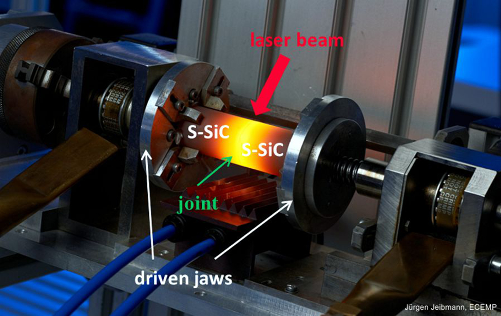
Laser joining of S-SiC capsule specimens
The laser beam was guided via a scanner with an optical element with f = 405 mm. Optimisation yielded an ellipse as the most suitable scan path. The optimum working distance between the fixed optical element and the cylinder surface was 250 mm, and the speed of rotation was 10·18 rads s− 1. For temperature measurement, an infrared camera (VarioCam hr, Infratec GmbH, Dresden, Germany) was used, and an emission coefficient of 0·86 was found for the S-SiC. 15
For the capsule geometry, a laser power of 1610 to 1740 W, depending on the glass filler system used, was found to be optimal. The laser power was increased according to a defined power–time profile and was decreased in a controlled manner to achieve cooling of the joined samples.
Capsule specimens were used for corrosion investigations, with the capsule size selected to ensure a seam thickness and contact surface similar to that used in practice. The capsule length was 80 mm, the outer diameter was 24 mm and the inner diameter was 16 mm. The wall thickness and pipe circumference are the same as the dimensions of the designated heat pipes. In addition, rod specimens with a total length of ∼70 mm (two joined rods, each 35 mm) and a diameter of 6 mm were annealed under the same conditions and used in four-point bending tests.
Silicate glasses in the MgO–Al2O3–SiO2 and Y2O3–Al2O3–SiO2 systems were selected for the filler systems. The requirements for selection of the glass systems were defined to be compatible with the SSiC base material and a high glass transition temperature. An SSiC similar expansion coefficient and a good wetting behaviour are required. Furthermore, a low melting temperature of < 1550°C is needed because the SiO2 protective layer of the SSiC base materials needs to be protected during the joining process.
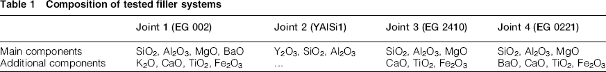
The selected alkaline earth glasses were commercially available (Ferro Ltd), whereas the yttrium containing glass was developed in house. 13 The components of the glass joint are listed in Table 1. Owing to the commercial nature of the materials, the exact composition is withheld from the analysis. Figure 2 shows one capsule sample, and Fig. 3 shows the original state of all four investigated joints. It can be seen that in the original state, a high quality of joint was achieved for joints 2 (YAlSi1), 3 (EG2410) and 4 (EG 0221). A very well filled joint with less gas inclusions and almost no cracks was achieved. Only joint 1 (EG 002) is of less quality, caused by a cyclic change in viscosity depending on laser temperature. Temperatures >1500°C led to opened bubble formation inside and outside the joined seam. Tight joints could not be produced under these conditions.
Composition of tested filler systems
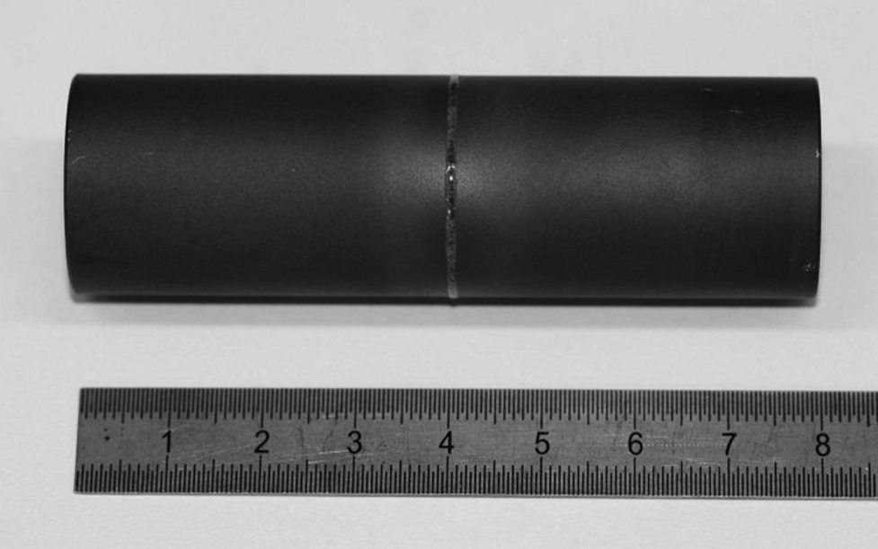
Investigated capsule sample
Original state of joints: joint 1 (EG002), joint 2 (YAlSi1), joint 3 (EG2410) and joint 4 (EG 0221)
For further details of the investigated samples and the laser joining process, the reader is referred to Börner et al. 15
To study the influence of steam, ash and alkali chlorides on the corrosion processes, the samples were exposed in a furnace at temperatures of 800–900°C in simulated producer gas at atmospheric pressure. In case of capsules, the bottom side of the samples was in contact with the ash. The total test time was 250 h, with cooling and subsequent reheating after an exposure time of 100 h. The atmosphere was set up similar to the allothermal fluidised bed gasifier in Güssing (Austria) that corresponds to the heat pipe employment conditions. At a temperature of 850°C, the gas consists under equilibrium of 36 vol.-% H2, 25 vol.-% CO, 17 vol.-% H2O (g), 11 vol.-% CO2 and 11% Ar (replacing all inert gases and hydrocarbons). 24 This composition was achieved by mixing the respective gases. A real gasifier wood ash from Güssing was used in the experiments. The composition of the ash is given in Table 2. The desired concentration of gaseous alkali species in atmosphere, i.e. 10 ppm NaCl and 400 ppm KCl, was achieved by evaporating alkaline salts inside the furnace. The experimental set-up is illustrated in Fig. 4.
Composition of gasifier wood chip ash from Gssing/mass-%

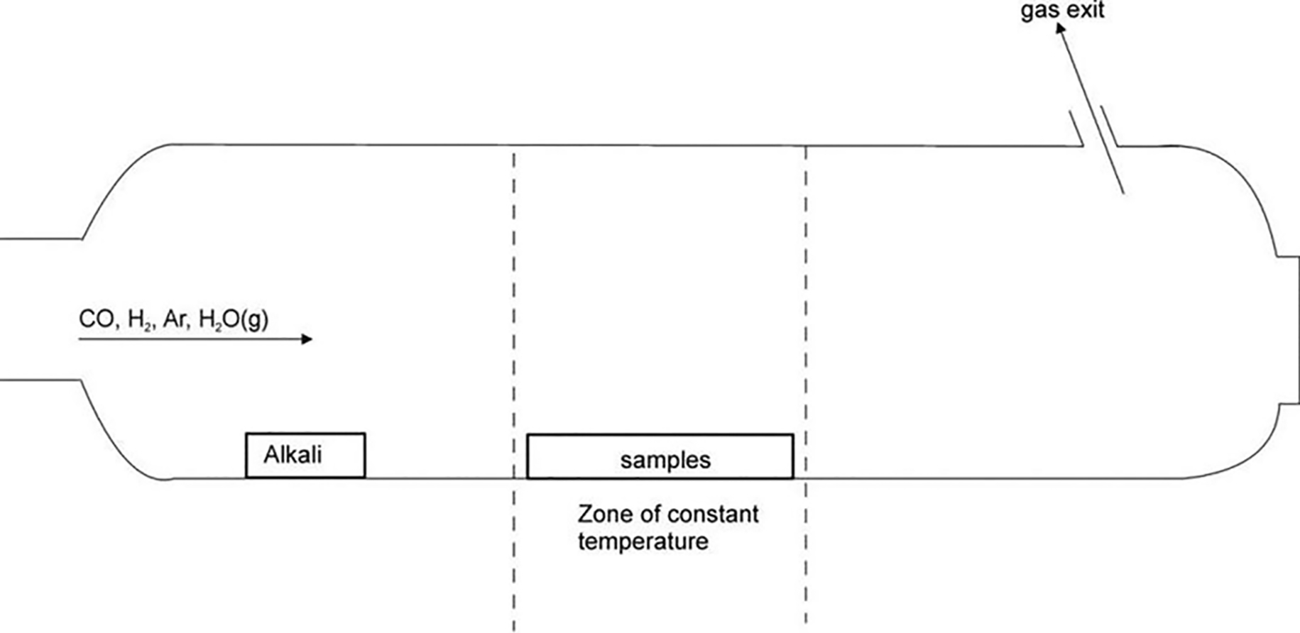
Experimental set-up for exposure experiments
After exposure, cross-sections of the samples were analysed by SEM and EDX to investigate the corrosion resistance of joint and base materials in the presence of water vapour and alkali rich atmosphere as well as the employed wood chip ash from Güssing. The investigations were done at three positions of the joint: (i) at the outside of the tube, which was in contact with the simulated producer gas and partly with the ash; (ii) in the middle of the joint; (iii) at the inside of the tube, which was not in contact with the simulated producer gas and ash and thus protected (Fig. 5). Afterwards, the corrosion behaviour was related to data on flexural strength and leakage rate after exposures at 850°C obtained by Börner et al. 15
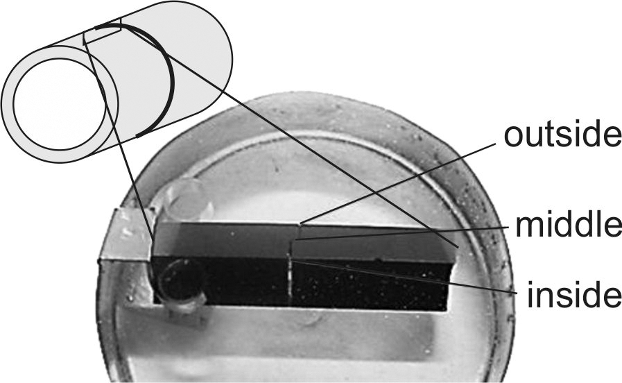
Investigated joint positions
The strengths of the ceramic glass joints were tested by four-point bending test in accordance with DIN EN 843-1. The measurement was done on a Zwick & Roell machine with control of the applied force (Fmax = 5 kN). The inner and outer spans were 20 and 40 mm respectively.
The tightness of the joints was obtained by means of a helium leak test with a mass spectrometer Phoenix XL 300. In the integral leak test, specimens are placed in a test chamber, evacuated and then pressurised with helium. Helium escaping due to leaks is suctioned by a high vacuum pump and detected.
Results
In general, after exposure at selected temperatures, the formation of cracks and gas inclusions in the joining materials could be observed in the cross-sections. Furthermore, absorption of alkali metals, especially potassium, took place, as EDX analysis revealed. The occurrence of corrosion attack depended on the investigated joint itself and exposure temperature.
The measured strength and leakage rate of the samples after exposure to gas atmosphere at 850°C are summarised in Table 3. For further details, the reader is referred to Börner et al. 15
Results of measured four-point flexural strength and leakage rate obtained by Brner et al. 15
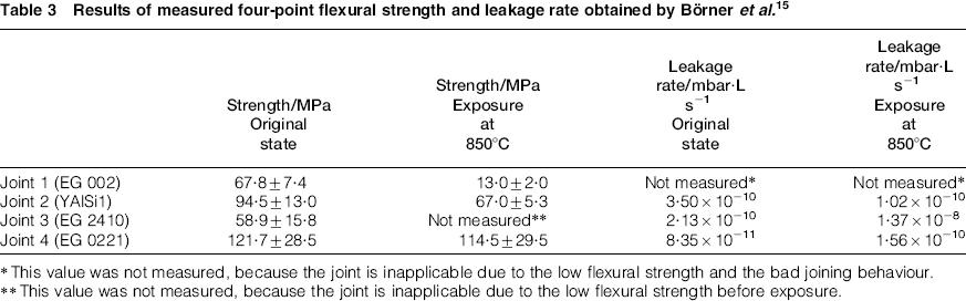
This value was not measured, because the joint is inapplicable due to the low flexural strength and the bad joining behaviour.
This value was not measured, because the joint is inapplicable due to the low flexural strength before exposure.
Joint 1 (EG 002)
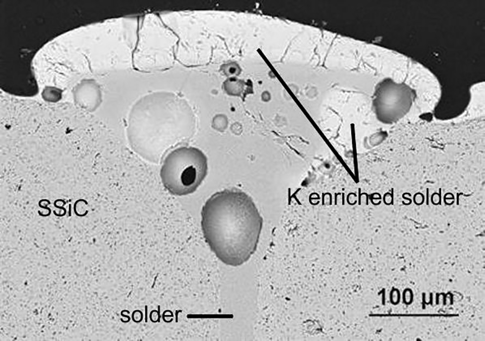
For joint 1, a very poor corrosion resistance was observed. Even at a temperature of 800°C, a distinct crack formation was observed at the outside of the tube, which was in contact with ash (Fig. 6). The crack formation was related to the adsorption of potassium up to a concentration of 12 at.-%. Furthermore, the formation of gas inclusions was observed after exposure, which caused spalling of the solder at a temperature of 900°C (Fig. 7). Both corrosion effects appear less in the middle and at the inside of the joint or after reaction with the atmosphere only. Figure 8 shows the well filled middle of the joint after exposure to gas atmosphere at 900°C. No corrosion effect was observed. Furthermore, no absorbed potassium could be detected.
Crack formation after exposure at 800°C [joint 1 (EG 002), ash, outside]
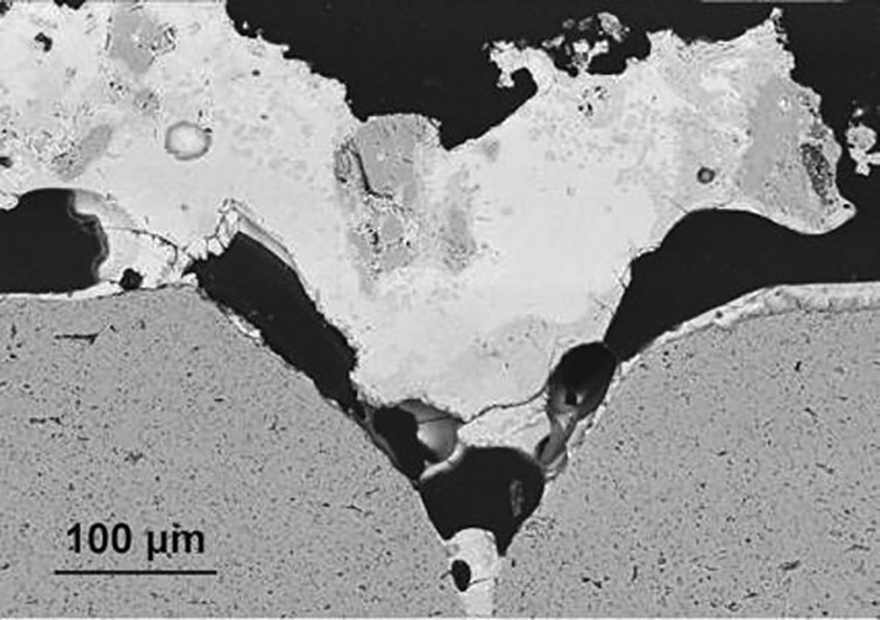
Joint spalling after exposure at 900°C [joint 1 (EG 002), ash, outside]
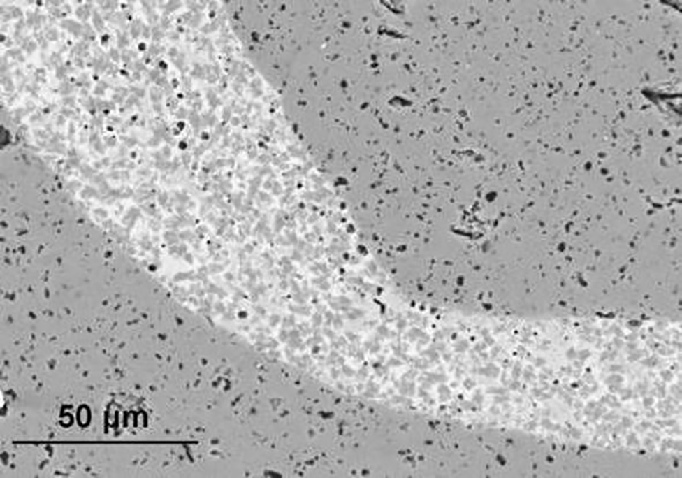
Well filled middle of joint after exposure at 900°C to gas atmosphere [joint 1 (EG 002), gas, middle]
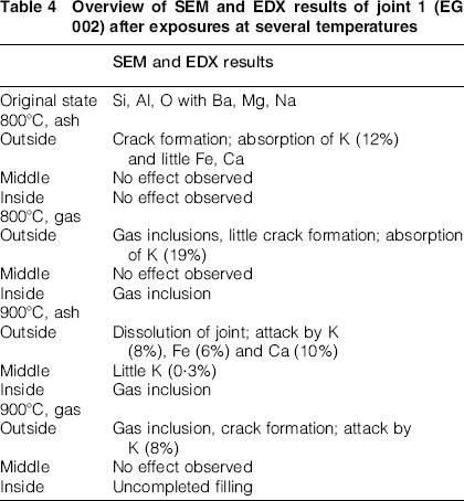
Table 4 gives an overview on SEM and EDX results for joint 1 after exposure at several temperatures. It needs to be mentioned that further investigations for joint 1 after exposure at 850°C were omitted because of the poor corrosion behaviour at 800°C and 900°C as well as the low flexural strength. 15 Hence, a reliable application of joint 1 is not possible in water vapour and alkali rich environments. Therefore, further investigations of this joint in a gasifier-like atmosphere are no longer pursued.
Overview of SEM and EDX results of joint 1 (EG 002) after exposures at several temperatures
Joint 2 (YAlSi1)
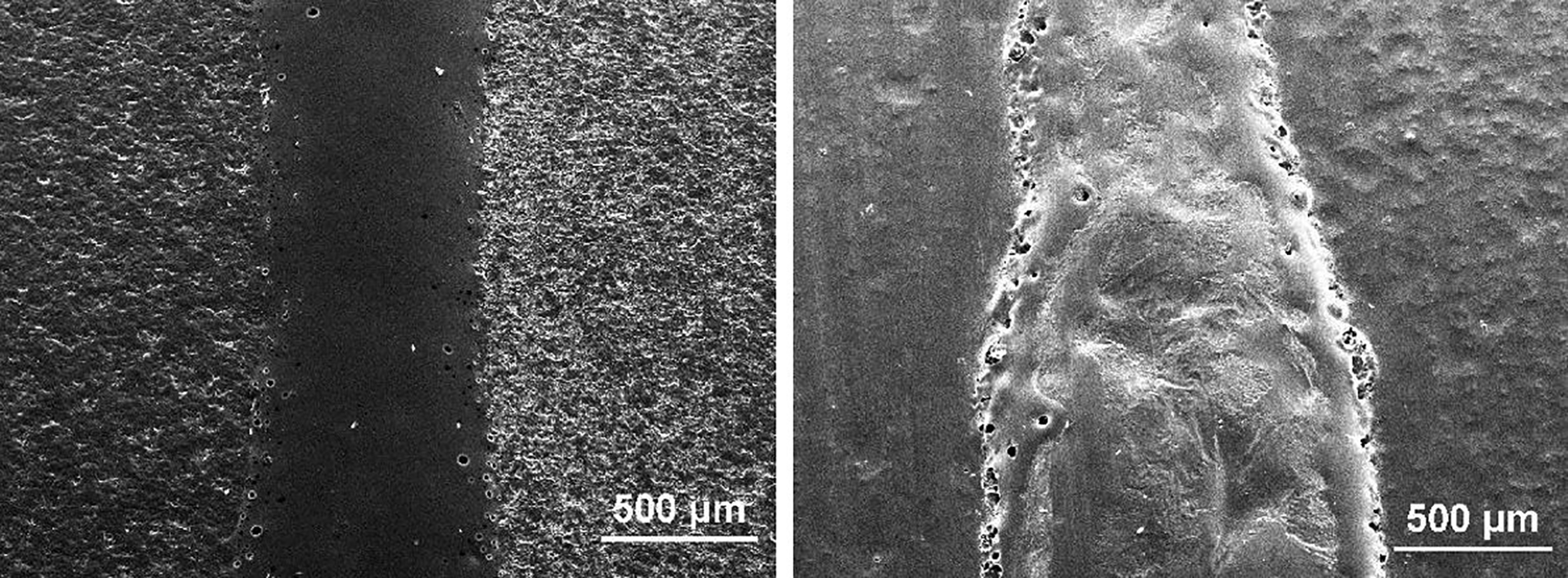
For joint 2, the best but with increasing temperature decreasing corrosion resistance was observed. After exposure to gas atmosphere at 800°C, only surficial cracks could be observed. However, after exposure at 900°C, the crack formation is more distinct, and additionally, gas inclusions were observed. The formation of gas bubbles especially occurred in the peripheral outer region of the seam (Fig. 9).
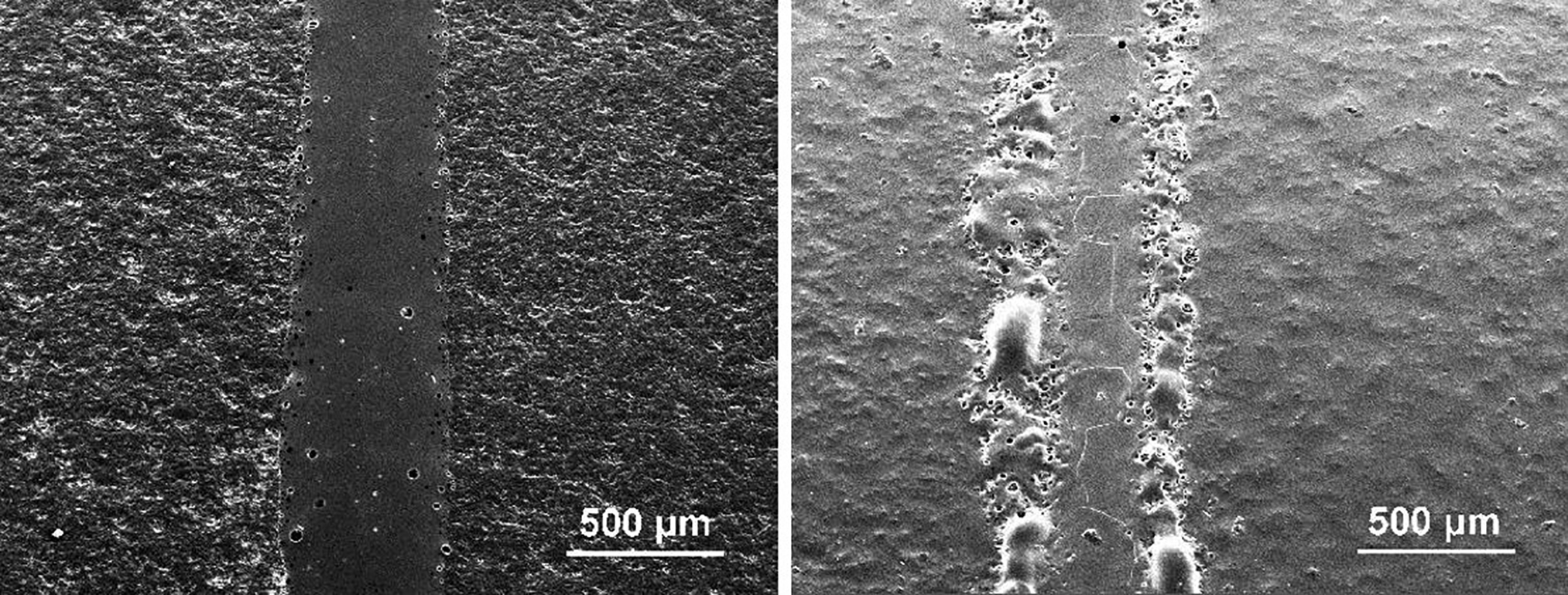
Comparison of outside of joint 2 before (left) and after (right) exposure to gas atmosphere at 850°C (pictures recording by Fraunhofer IKTS, Dresden)
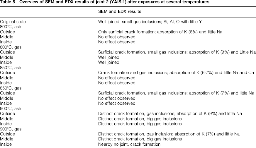
Figure 10 shows a comparison of joint 2 at the outside of the tube after exposures to gas atmosphere and ash at 800°C, 850°C and 900°C. Beside the visible formation of gas inclusions and cracks, the adsorption of potassium and little amounts of sodium was detected by EDX in the filler material at the outside of the joint at each temperature. The corrosion effects are less at the inside and in the middle of the joint. Furthermore, no potassium was detected by EDX at these positions. Table 5 gives an overview of SEM and EDX results for joint 2 after exposure at several temperatures.
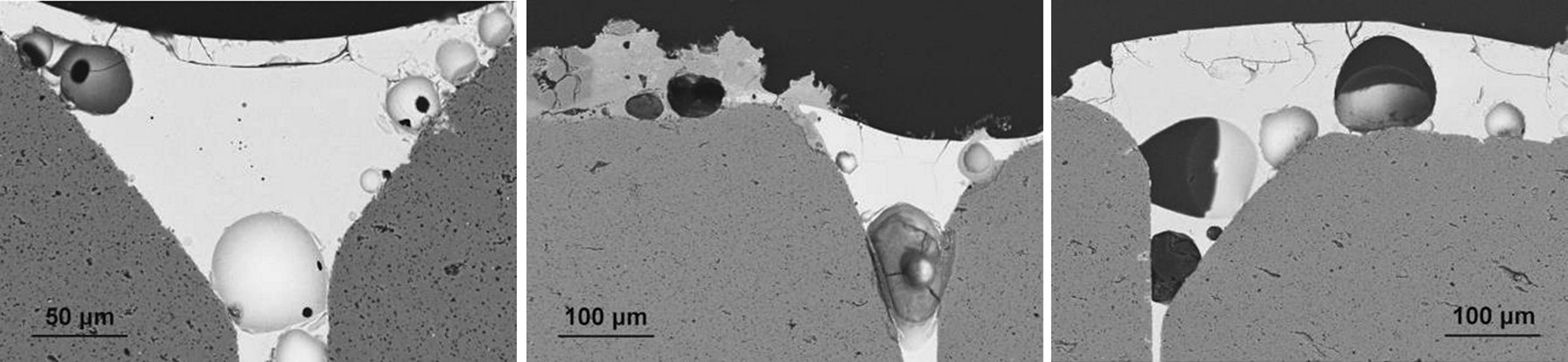
Comparison of joint 2 after exposure at 800°C (left), 850°C (middle) and 900°C (right) [joint 2 (YAlSi1), ash, outside]
Overview of SEM and EDX results of joint 2 (YAlSi1) after exposures at several temperatures
These results are consistent with the trends of leakage rate and flexural strength investigated by Börner et al. 15 presented in Table 3. After exposure at 850°C, a low leakage rate of 1·452 × 10− 10 mbar·L s− 1 and a relatively high flexural strength of 67 MPa were measured. This can be confirmed by the acceptable corrosion resistance at this temperature (Table 5).
Joint 3 (EG 2410)
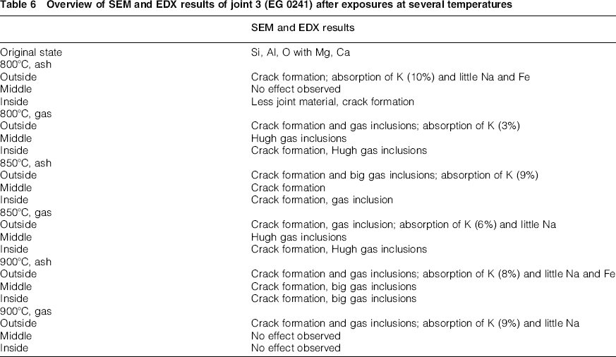
For joint 3, a very poor corrosion resistance was observed. Although joint 3 is well joined and shows good behaviour in its original state, even at low temperatures, the corrosion effects are more distinct compared to the other joints. Furthermore, the SEM investigations showed that even after exposure to gas atmosphere only, the corrosion effects are explicit. Many gas inclusions and crack formation were observed. Figure 11 shows all three investigated joint areas after exposure to gas atmosphere at a temperature of 800°C. Table 6 gives an overview of SEM and EDX results for joint 2 after exposure at several temperatures.
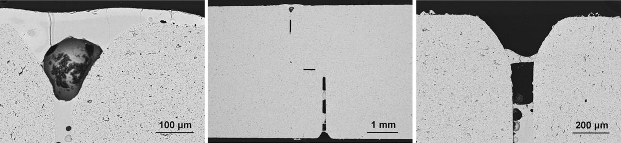
Outside (left), middle (middle) and inside (right) of joint 3 after exposure to gas atmosphere at 800°C
Overview of SEM and EDX results of joint 3 (EG 0241) after exposures at several temperatures
The poor corrosion resistance explains the low flexural strength and the increasing leakage rate after exposures (Table 3).
Joint 4 (EG 0221)
Joint 4 showed the highest flexural strength and lowest leakage rate (Table 3). After exposure to gas atmosphere at 850°C, a leakage rate of 1·558 × 10− 10 mbar·L s− 1 and a flexural strength of 114·5 MPa were measured.
In addition, the corrosion resistance was very good, especially up to a temperature of 850°C. Only surficial small cracks and little gas inclusions were observed. Similar to joint 2, gas inclusions formed in the solder at the interface to the SSiC base material (Fig. 12).
Comparison of outside of joint 4 before (left) and after (right) exposure to gas atmosphere at 850°C (pictures recording by Fraunhofer IKTS, Dresden)
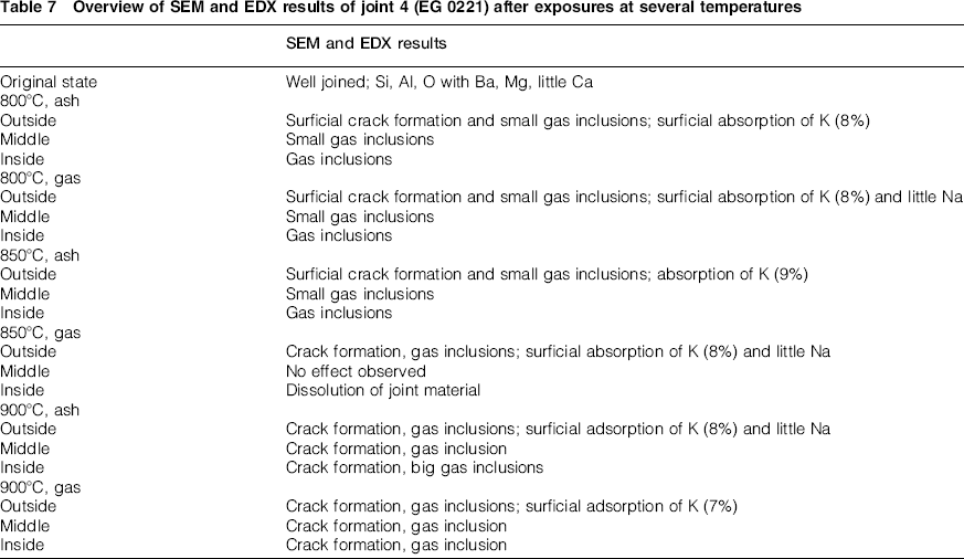
After exposure to gas atmosphere and ash at a temperature of 900°C, the crack formation increased but was still less than in joint 1 or joint 3. Figure 13 shows a comparison of joint 4 after exposures at 800°C, 850°C and 900°C. Furthermore, at each temperature, the adsorption of potassium and little amounts of sodium was observed. Table 7 gives an overview of SEM and EDX results for joint 4 after exposure at several temperatures.
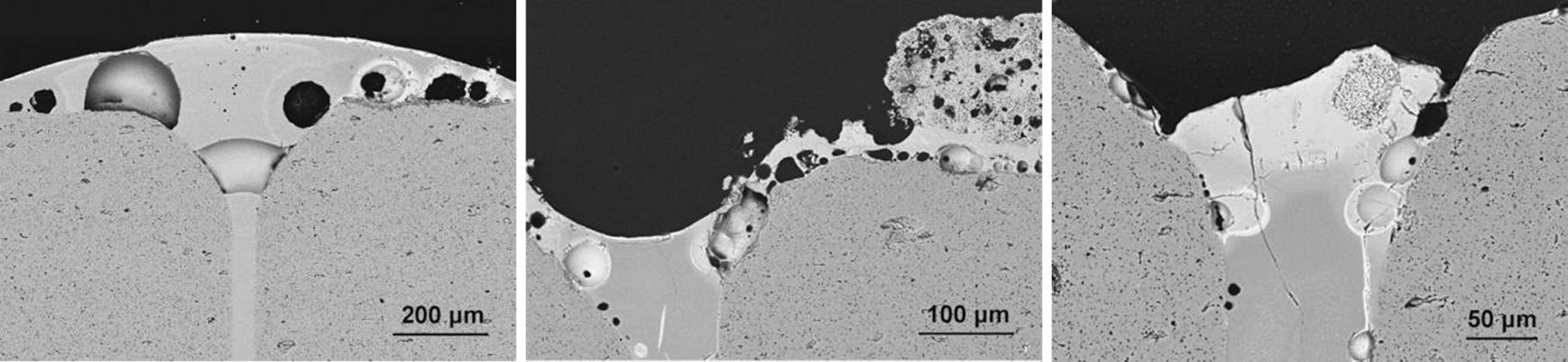
Comparison of joint 4 after exposure at 800°C (left), 850°C (middle) and 900°C (right) [joint 4 (EG 0221), ash, outside]
Overview of SEM and EDX results of joint 4 (EG 0221) after exposures at several temperatures
SSiC base material
Significant corrosion effects on the SSiC base material, like vapourisation, water vapour oxidation or crack formation, were not observed. Only the formation of a SiO2 glass layer (Fig. 14) with slight alkali and alkaline earth metal oxide inclusions on the SSiC surface was observed for both conditions, without and with ash. The formation can be explained by water vapour caused oxidation25,26 and is typical for this kind of material.
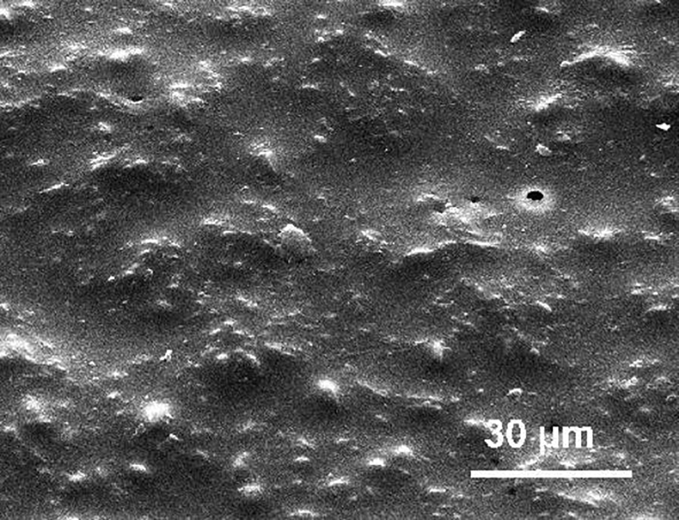
Glass layer on SSiC surface (outside) after exposure to gas atmosphere at 850°C (picture recording by Fraunhofer IKTS, Dresden)
Discussion
Formation of potassium aluminosilicates
After each exposure, independent of temperature and ash or gas atmosphere influence, the absorption of potassium (and little amounts of sodium) was observed at the outside of the joint. Changes in the middle or at the inside could not be observed. After exposure to ash, the effect was more distinct compared to gas atmosphere only. This can be explained by the higher reaction rate due to the continuous direct contact to the ash containing a high amount of potassium.
Fig. 15 shows an EDX mapping of joint 1 (EG 002) after exposure to gas atmosphere only and ash at 900°C in comparison to the original state. It can be seen that the potassium absorption is localised in the joint material due to its aluminosilicate character. Aluminosilicates, in particular, are well known for alkali absorption. In equilibrium, the absorption of potassium in aluminosilicates, or even the formation of potassium aluminosilicates, is preferred. 27 No potassium was detected in the SiC structural material.
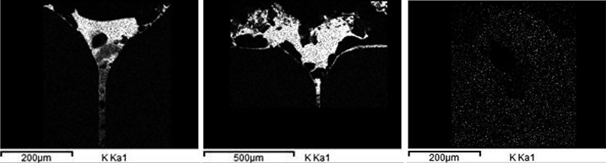
EDX mapping of outside of joint 1 (EG 002) after exposure at 900°C to gasifier atmosphere only (left) and ash (middle) compared to original state (right)
The absorption of potassium was more distinct in comparison to sodium due to the simulated gasifier-like atmosphere that contains much more potassium than sodium and the preferred absorption of potassium in aluminosilicates. 28
The amount of potassium that can be absorbed by the joint material depends on its overall composition. While in crystalline phases usually stoichiometric amounts of alkali oxides are bound in aluminosilicates, in case of solution phases like melts and glasses also non-stoichiometric amounts are possible. In silicate glasses, silica forms a network. Alumina as an intermediate oxide can substitute silica in four-fold coordination by charge balancing with a cation in the vicinity, in this case potassium. This means that the alkali vapour pressure above an alkali aluminosilicate melt increases if the amount of alkali oxides exceeds the amount of alumina. Thus, the amount of alumina determines, to some extent, the maximum absorption of alkalis. However, other basic oxides, especially alkaline earth oxides like MgO, do also compensate alumina. In addition, alkaline earth aluminosilicates are usually more stable than alkali aluminosilicates. Thus, the amount of ‘uncompensated’ alumina mainly determines the amount of absorbed potassium. Unfortunately, the exact composition of the joint materials must not be published so that quantitative conclusions are not possible. However, as the EDX analyses reveal, joint materials 1 and 3 adsorb more potassium than do joint materials 2 und 4. Since filler systems 1, 3 and 4 contain almost the same oxides, their ratio in system 4 seems to be beneficial, i.e. more balanced, in comparison to the other systems. In addition, system 2 containing Y2O3 has obviously a relatively low capacity for alkalis.
The absorption of alkaline metals induces a problem for the reliable application of the investigated joints due to the decrease of glass transition temperature and melting point. Furthermore, the adsorption of potassium and the formation of a potassium aluminosilicate glass phase seem to cause the observed cracks in the joint material and promote the formation of gas bubbles as discussed below.
As the major corrosion effects are caused by potassium absorption, the overall corrosion resistance of the several joint materials can directly be correlated with the amount of absorbed potassium. Joint materials 1 and 3 showing poor corrosion resistance contained up to 19% K and 10% K respectively after exposure at 800°C, whereas joints 2 and 4 showing the good corrosion resistance only contained 8% K. The trends at higher temperatures are similar. Furthermore, the order of measured flexural strength and leakage rate correlates well with the order of potassium adsorption by the joint materials.
Crack formation
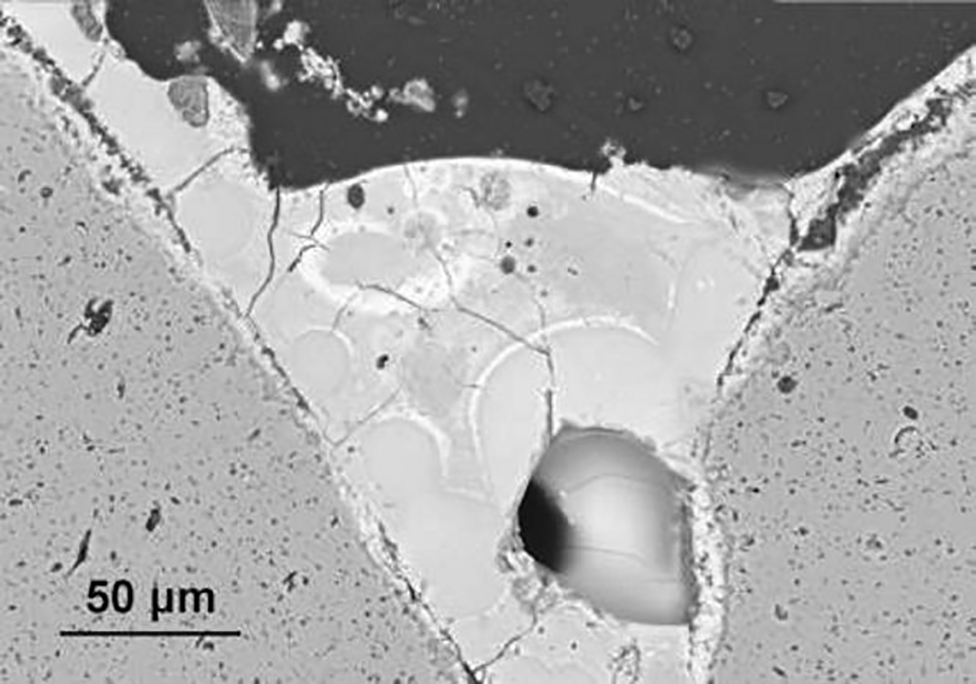
Crack formation seems to be caused by the adsorption of alkaline metals, especially the formation of a potassium aluminosilicate glass as SEM/EDX analysis reveals. Cracks only occur in alkali enriched regions of the joint. The formation of a new phase causes most likely changes in the lattice parameters and the coefficient of expansion. Both effects can be seen as the main reason of crack formation. In Fig. 16, the phase transition caused by potassium and the beginning crack propagation can be seen well.
Phase transition and crack formation caused by potassium and beginning crack propagation in joint 3 after exposure to gas atmosphere at 900°C [joint 3 (EG 2410), gas, outside]
Crack formation caused by alkali metals can be well distinguished from crack formation caused by the sample cutting process. These cracks are more periodic, as shown in Fig. 17.
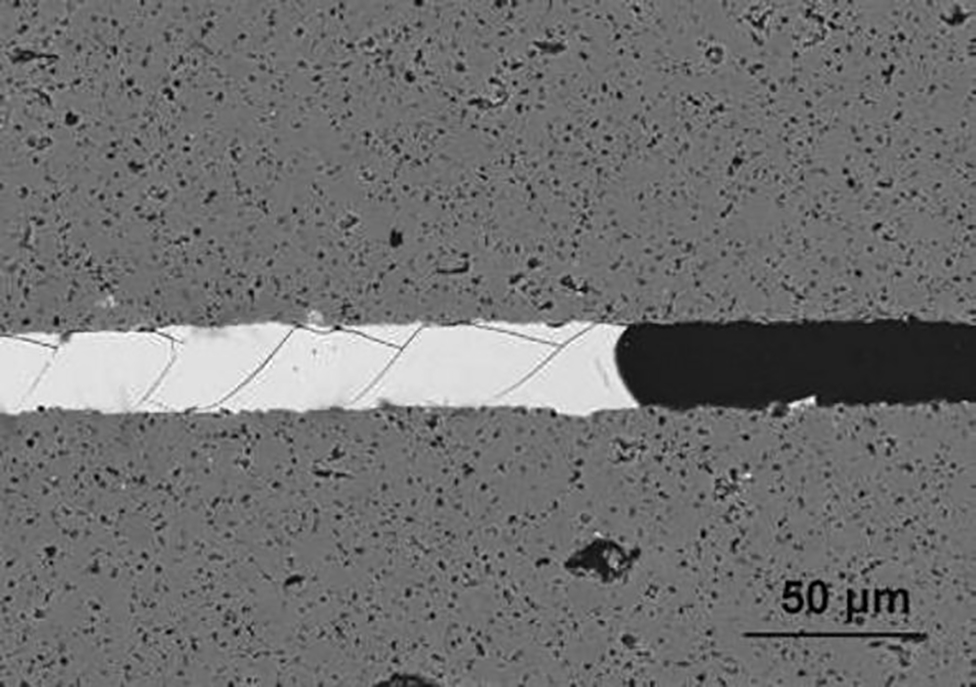
Periodic crack formation caused by cutting process [joint 2 (YAlSi1), middle]
Crack formation induces a problem for reliable application of investigated joints due to the associated decrease in flexural strength (Table 3). Thus, crack formation in joints causes a relevant loss in heat exchanger stability and reliability.
Gas inclusions
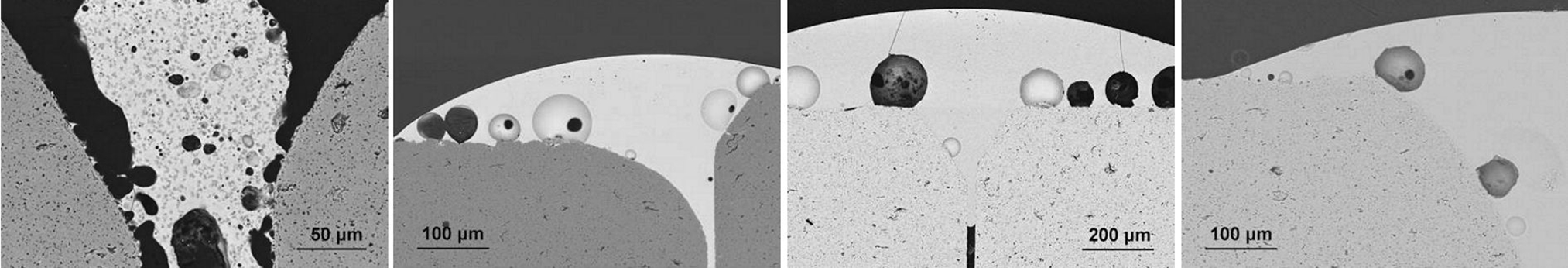
In principle, the gas inclusions can be divided into two groups. Especially joint 1 showed gas inclusions already after the joining process. In this case, the gas inclusions are completely surrounded by the glass matrix and have no influence on the joint tightness. The tightness of the joint is guaranteed by the continuous and faultless areas connecting both joined SSiC parts (Fig. 18). The content and dimension of gas inclusions depend on the joining temperature, the filler amount and its viscosity at the process temperature.
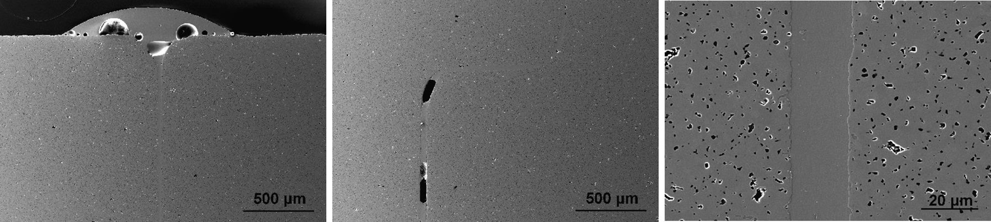
Gas inclusions at outside (left) and in middle (middle) and well filled areas in middle (right) of joint 2 after joining process (pictures recording by Fraunhofer IKTS, Dresden)
In the other case, the gas inclusions form during exposure. Depending on joint material, temperature and investigated joint position, this effect was differently distinct. Figure 19 shows gas inclusions in joint 4 after exposure to gas atmosphere at 800°C. Even inside the joint, the formation of gas inclusions was very distinct and showed an influence on the joint tightness. Furthermore, it is well visible that gas inclusions start to form at the interface between SSiC base material and joint material (also compare to Fig. 12).
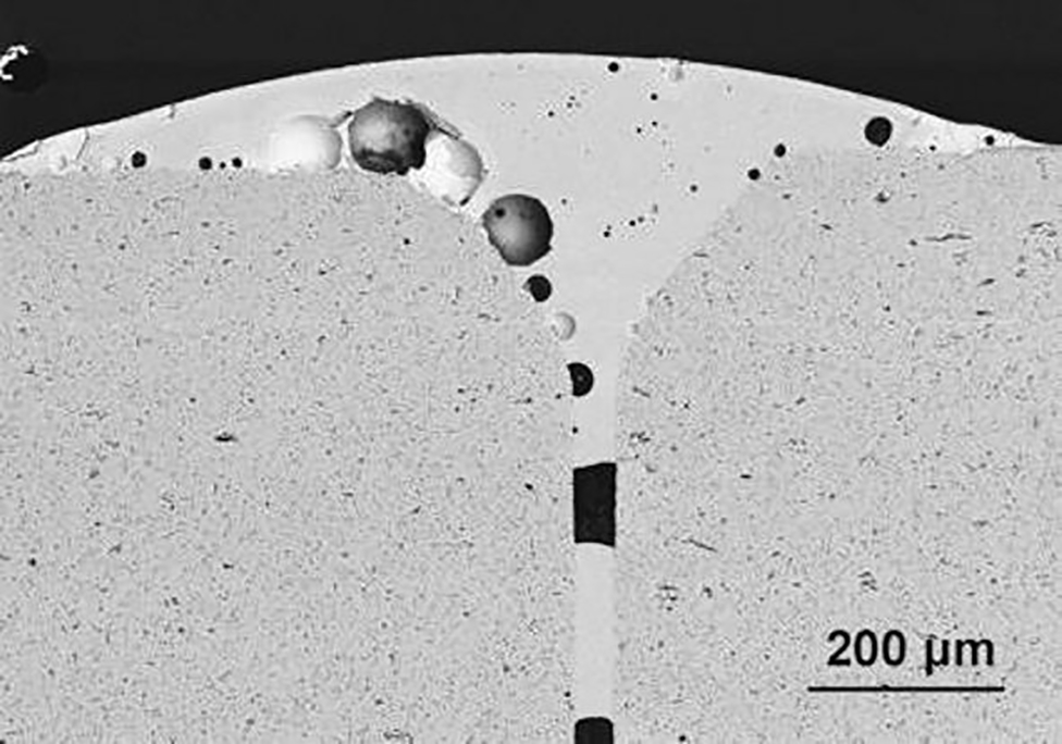
Gas inclusions in joint 4 after exposure to gas atmosphere at 800°C [joint 4 (EG 0221), gas, inside]
In general, it was observed that an increased temperature promotes the formation of gas inclusions. Furthermore, in most cases, the effect was more distinct after exposure to gas atmosphere. From this observation, it can be assumed that the responsible reaction is caused by the atmosphere. The most probable reason can be found in the water vapour content of the atmosphere. It is well known that water vapour leads to distinct corrosion effects on silica based materials.25,26 In this case, the hydration of aluminosilicates29,30 or especially the oxidation of the silicon carbide31–33 can cause the formation of volatile reaction components that expand the joint material. Furthermore, these corrosion mechanisms are promoted by the presence of alkali compounds.25,26,34 Owing to the preferred absorption of alkali metals by the aluminosilicate joint material and the resulting higher diffusion rate, the oxidation of the SiC base material is most distinct at the interface between joint and base material, especially in case of high alkali content, e.g. joints 1 and 3. In case of joint 1, which showed the highest amount of absorbed alkalis, the gas inclusions even cause spalling of the filler material.
Gas inclusions and vapourisation of joint material cause an increase of leakage rate and need to be prevented. Reliable heat pipes need to have highly sealed joints to guarantee a reliable working.
Conclusion
Exposures of aluminosilicate joints to wood chip ash and a reducing water vapour and alkali rich atmosphere at 800–900°C and atmospheric pressure caused three different microstructural corrosion effects. Depending on exposure temperature, joint position and joint material, differently distinct potassium absorption, crack formation and formation of gas inclusions were observed. Crack formation causes a decrease of stability, while gas inclusions cause a high leakage rate. Especially at temperatures >850°C, the corrosion attack affects the failure of joints. Therefore, the application temperature has to be limited to temperatures < 850°C if the investigated materials shall be used.
Especially, joint 1 (EG 002) and joint 3 (EG 2410), which are both mainly based on SiO2, Al2O3 and MgO, showed poor corrosion resistance combined with low flexural strength and relatively high leakage rate. Hence, these two materials are not feasible for application in gasification processes.
Joint 4 (EG 0221), which is mainly based on SiO2, Al2O3 and MgO, and joint 2 (YAlSi1), which consists of SiO2, Al2O3 and Y2O3, showed relatively good corrosion resistance. Still, further long time investigations are necessary and the composition of the solders may need to be improved, but in general, the application in gasification processes is conceivable.
Acknowledgements
This work is part of the DER project, supported by ‘Bundesministerium für Bildung und Forschung’ (FKZ 03IS52021F).