
Abstract
Cf/ZrC, Cf/SiC and Cf/ZrC–SiC composites were successfully prepared by polymer infiltration and pyrolysis (PIP) using polycarbosilane and a liquid ZrC precursor. The densification process, mechanical properties and microstructures were studied in a view of comparison. After the same total 20 PIP cycles, the Cf/ZrC, Cf/SiC and Cf/ZrC–SiC composites had flexural strengths of 50.1±5.3, 285.7±22.6, 141.5±13.1 MPa respectively; elastic moduli of 7.8±0.9, 57.1±3.2 and 45.1±2.6 GPa respectively; and fracture toughness of 2.5±0.2, 10.4±0.9 and 10.9±1.1 MPa m1/2 respectively. With the introduction of high modulus SiC phase into the ZrC matrix, the densification and modulus of the matrix were improved; as a result, the Cf/ZrC–SiC composite showed higher mechanical properties compared to Cf/ZrC.
Introduction
The design and production of new materials suitable to external thermal protection systems are currently stimulated by the recent resurgence of interest in hypersonic vehicles.1,2 At this time, SiC based composites have received considerable attention for its comprehensive properties at high temperature. However, the long term use temperatures of SiC based ceramics are limited to ∼1600uC due to the onset of active oxidation.3,4 Ultrahigh temperature ceramics (UHTCs), which are refer to those refractory transition metal borides, carbides and nitrides with melting points of over 3000uC, are of particular interest for high temperature applications.5,6 Especially, continuous fibre reinforced UHTC composite such as C/ZrC–SiC, which overcomes the inherent brittleness of monolithic UHTCs, and also has the ability to be formed into complex shapes with large size, is one of the most promising material systems for ultrahigh temperature applications.7,8
At present, various techniques9 10 –11 are utilised to fabricate ZrC based composites. The PIP process involving the use of liquid ZrC precursor is a promising approach, as this technique allows improving homogeneous distribution of ZrC in the composites and increasing the ZrC content. There are a number of reports in the literature describing the mechanical properties and microstructures of the ZrC based and Cf/SiC composites by PIP process. Zhao et al. 12 reported the microstructural, mechanical and ablative properties of three-dimensional (3D) C/ZrC composite. Li et al.11 fabricated properties of 3D Cf/SiC–ZrC composites. Jian et al. 13 discussed the influences of heating rate and pyrolysis temperature on the microstructure and mechanical properties of Cf/SiC. However, the separate study on the mechanical property and microstructures of the Cf/ZrC, Cf/SiC and Cf/ZrC–SiC composites is not enough to provide details for the applications of ZrC based composites. This necessitates the study on the mechanical properties and microstructures of the Cf/ZrC, Cf/SiC and Cf/ZrC–SiC composites in a view of comparison under the same conditions.
In this paper, we fabricated the Cf/ZrC, Cf/SiC and Cf/ZrC–SiC composites using ZrC precursor/polycarbosilane. Their densification behaviour, mechanical properties and microstructures were studied and compared to provide more details for the mechanical behaviour of the composites, so as to find a solution to improve the mechanical properties of the ZrC based composites.
Experimental
Polyacrylonitrile based carbon fibre bundles (T300, 3 K, Toray, Tokyo, Japan) were woven into 3D (three-dimensional, four-directional) preforms with a ∼46 vol.-%. Then, in order to obtain the fibre protection, a SiC layer was deposited on the fibre preforms of the Cf/ZrC and Cf/ZrC–SiC composites by chemical vapour deposition, using MTS/H2 precursor. The ZrC precursor made from organic complex (acetylacetone as the ligand) combined with phenolic resin had a ceramic yield of ∼38 wt-% 14 and studied the microstructure and mechanical The polycarbosilane (PCS, with a ceramic yield of ∼65 wt-%) was utilised as a precursor to form SiC matrix. The preforms were impregnated by the abovementioned ZrC precursor and then dried and pyrolysed at 1000uC for 1 h in flowing argon. Then, one preform was followed by another 19 PIP cycles with ZrC precursor to prepare the green Cf/ZrC composite, and another was followed by further 12 cycles to obtain the primary product for the Cf/ZrC–SiC composite. Next, the composites were heat treated at 1550uC for 2 h after the 10th and final cycles for completing the carbothermal reduction to form Cf/ZrC composites. Finally, Cf/ ZrC composite with 13 PIP cycles of ZrC precursor was densified by seven PIP cycles of PCS to get a total 20 cycles to form the Cf/ZrC–SiC composite. The Cf/SiC composite was obtained by 20 PIP cycles using PCS, and the pyrolysis of PCS was carried out at 1200uC for 1 h in flowing argon.
The apparent density and open porosity were measured by Archimedes’ method. The composites were cut into 4×5×60 mm specimens and polished for a three-point bending test in a WDW-100 (Changchun Research Institute of Testing Machines, Jilin, China) universal testing machine, with a crosshead speed of 0.5 mm min−1 and a span of 50 mm. Young's modulus was obtained from the slope of the flexural curve at the initial linear domain. Fracture toughness KIC was measured by single edge notched beam method. 15 The microstructures were investigated by scanning electron microscopy (SEM, S4800 Hitachi, Japan). The phase compositions of the composites were characterised by X-ray diffraction (XRD, D8 Advance, Bruker/Axs Corp., Germany) with Cu Ka radiation.
Results and discussion
The densification behaviour of Cf/ZrC, Cf/SiC and Cf/ZrC– SiC composites is shown in Fig. 1. The densification curves of Cf/SiC show that the densification of the composites is quite fast in the early PIP cycles. With the growth of PIP cycles, the accessible open porosity becomes less, resulting in slower density increase. As far as the Cf/ZrC composite is concerned, as a whole trend, the density increases with the growth of the PIP cycles, and the open porosity decreases accordingly. However, after the heat treatment at 1550uC, a few turnover points appear on both of the density and open porosity curves, indicating the decrease in the density and increase in the open porosity, which is attributed to the mass loss resulting from the carbothermal reaction. The turnover points also take place in the densification curves of the Cf/ ZrC–SiC composites for the same reason. It can be observed that the densification process of the Cf/ZrC–SiC composite is accelerated with introduction of SiC into ZrC matrix, which results in higher density and lower porosity of the Cf/ ZrC–SiC composite in comparison with that of Cf/ZrC with the same total PIP cycles. After the same total 20 PIP cycles, the densities and open porosity of Cf/ZrC, Cf/SiC and Cf/ ZrC–SiC composites are 2.05, 1.95 and 2.10 g cm−3 and 30, 9 and 16% respectively.
Densification behaviour of a Cf/ZrC, b Cf/SiC and c Cf/ ZrC–SiC composites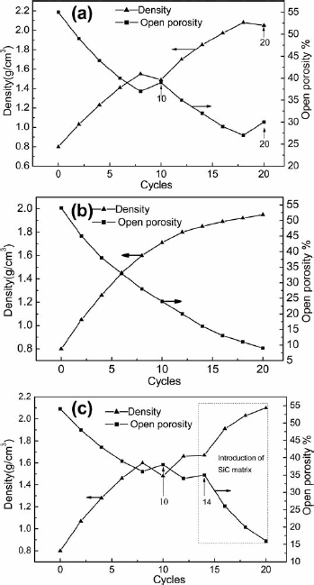
The XRD patterns of the Cf/ZrC, Cf/SiC and Cf/ZrC– SiC composites are shown in Fig. 2. It can be observed from XRD pattern of the Cf/ZrC–SiC composite that the matrix contains the main phase of ZrC and minor phase of SiC, indicating that the ZrC matrix was formed. The XRD pattern of the Cf/ZrC composite indicates that it has the only matrix of ZrC, and its diffraction peaks are sharp and strong. However, the diffraction peaks of SiC matrix in Cf/SiC composite are weak and broad. It can be concluded that the ZrC matrix shows good crystallisation, while the SiC shows poor crystallisation, which, to some extent, can be regarded as amorphous state.
X-ray diffraction patterns of Cf/ZrC, Cf/SiC and Cf/ZrC–SiC composites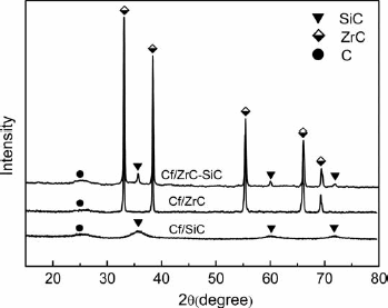
Properties of Cf/ZrC, Cf/SiC and Cf/ZrC–SiC composites
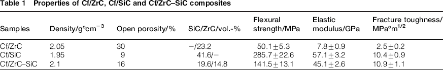
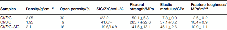
Figure 3 shows the load–displacement curves of Cf/ ZrC, Cf/SiC and Cf/ZrC–SiC composites. It can be concluded from these curves that three samples show a different fracture behaviour. The load–displacement curve of Cf/ZrC shows that the load grows slowly with the increase in displacement, and then, the curve has a long load retention zone until it starts to decrease slowly. However, the load–displacement curve of Cf/SiC goes through an initial linear domain, and then, a few turnover points (dashed line zone in Fig. 3b) to reach the peak load, at last, decreases abruptly. The load–displacement curve of Cf/ZrC–SiC shows a similar initial linear domain to that of Cf/SiC; however, the curve decreases slowly after the peak load (dashed line zone in Fig. 3c), indicating a typical non-brittle fracture behaviour. It can be observed from the load–displacement curve of the Cf/ZrC–SiC composite that the slope of the initial linear domain increases significantly in comparison with that of Cf/ZrC, indicating that higher modulus of the ZrC–SiC matrix has been obtained with the introduction of SiC.
Load–displacement curves of a Cf/ZrC, b Cf/SiC and c Cf/ ZrC–SiC composites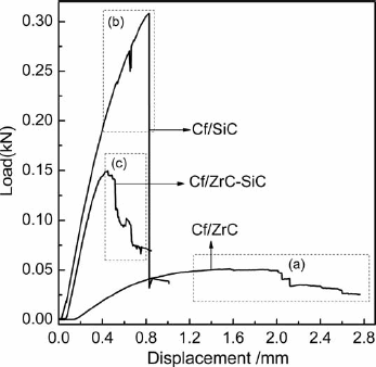
The microstructures of the polished cross-sections of composites are shown in Fig. 4. It can be seen from the polished cross-sections of Cf/ZrC composite that there are many macropores between the fibre bundles, while in the intrabundle areas, the matrix is composed of undebonding ZrC particles with distribution of many micropores among them. As far as the Cf/SiC is concerned, some closed pores are distributed between fibre bundles as those areas are nearly inaccessible; however, the matrix in the intrabundle areas is dense and continuous. After introduction of SiC, the matrix of the Cf/ ZrC–SiC composite is much denser than that of Cf/ZrC composite, both for the interbundle and intrabundle areas. The different features of the precursors and their pyrolysed products can explain the different microstructures of the composites. The liquid ZrC precursor is easily inserted into the intrabundle zones, which accounts for much more undebonding ZrC matrix in the intrabundle areas. On the other hand, in addition to its low ceramic yield, the liquid ZrC precursor having a typical density of ∼1 g cm−3 transforms into crystal ZrC ceramic products of higher density (∼6 g cm−3) after the high temperature treatment, which results in volume shrinkage of the matrix with production of large numbers of pores. In contrast, the PCS has a ceramic yield of 65 wt-%, almost twice of that of the ZrC pre-cursor; furthermore, its pyrolysed product has a lower density of ∼2.4 g cm23, resulting in less volume shrinkage during pyrolysis. Therefore, the Cf/SiC composite has a much denser matrix compared with that of Cf/ZrC composite. It is noteworthy that the pores existing in the ZrC matrix can provide infiltration channels for the PCS infiltration; thus, the densification of the ZrC–SiC matrix is improved. However, some micropores and microcracks still appear in the Cf/ZrC– SiC composite for the porous feature of the initial ZrC matrix and the inevitable shrinkage of the following PCS after pyrolysis.
Images (SEM) on polished cross-sections of a, b Cf/ZrC, c, d Cf/SiC and e, f Cf/ZrC–SiC composites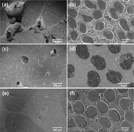
As shown in Fig. 5, Cf/SiC composite has a denser matrix in comparison with Cf/ZrC composite. With little glue effect of the porous ZrC matrix, the fibres in Cf/ZrC composite present loose, and the pulled out fibres are long. In contrast, the SiC matrix is much denser, which glues the fibres tightly and limits the fibre pullout length. As confirmed by Fig. 5c and d, the whole fibre bundle fractures, and the pulled out filament is short. The sliding appearance of fibres along the matrix and the crack deflection around the fibres (the arrows denotes in Fig. 5d) can be visibly observed, which increase the toughness. In consistence with the non-brittle fracture behaviour of Cf/ZrC–SiC composites, the composites cannot only ensure fibre bundles pullouts (Fig. 5e) but also ensure the single filament pullout mechanism (Fig. 5f). The fibre pullouts accompanied with dissipation mechanisms of crack energy, such as fibre bridging, crack deflection (the arrows denotes in Fig. 5f) and fibre breaking can increase the damage tolerance of the composites. Thus, the relatively high bending strength along with dissipation mechanisms of crack energy accounts for the higher fracture toughness of the Cf/SiC and Cf/ZrC–SiC composites.
Images (SEM) on fracture surfaces of a, b Cf/ZrC, c, d Cf/SiC and e, f Cf/ZrC–SiC composites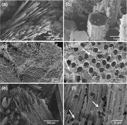
For further understanding the relationship between mechanical behaviour and microstructures of the composites, more results and details should be revealed and discussed. Fibre preforms and matrix are the two main factors determining the mechanical property of the composites. In this paper, the fibre preforms have the same structures and volume content; thus, they can be regarded as a secondary factor. Hence, the main attention is paid to the matrix. As we all know, in the continuous fibre reinforced ceramic matrix composites, the modulus of matrix is usually close to that of the fibres; thus, the matrix and fibres carry the nearly equal proportion of load during the bending strength test. Additionally, to much extent, the modulus of the composite is determined by the modulus of the matrix as the fibre preform has a lower modulus. In our case, the modulus of SiC matrix measured by nanoindentation tests is 154.9 GPa, while the ZrC matrix is not very suitable for this test for its porous feature. It can be deduced that the porous ZrC matrix has a lower modulus. Therefore, the fibres carry most of the load in the case of Cf/ZrC composite, but bending a fibre bundle does not require much force but results in large displacement, leading to the very low bending strength and modulus of the Cf/ZrC composite. In contrast, the modulus of SiC matrix is high, which is closer to that of carbon fibres; hence, the matrix can carry large part of load, resulting in high strength and modulus of the Cf/SiC composite. With the introduction of the SiC into ZrC, the densification and modulus of the ZrC–SiC matrix is improved, which can glue fibres tightly; as a result, the modulus and strength of the Cf/ ZrC–SiC composite grows accordingly. Therefore, improving the densification and modulus of the matrix is a feasible solution to improve the mechanical property of fibre reinforced ZrC based composites.
Conclusions
Cf/ZrC, Cf/SiC and Cf/ZrC–SiC composites were successfully fabricated using PCS and a liquid ZrC precursor. After the same total 20 PIP cycles, the densities and open porosity of Cf/ZrC, Cf/SiC and Cf/ZrC–SiC composites are 2.05, 1.95, 2.10 g cm−3 and 30, 9 and 16% respectively. The Cf/ZrC, Cf/SiC and Cf/ZrC–SiC composites have flexural strength of 50.1±5.3, 285.7±22.6 and 141.5±13.1 MPa respectively; elastic modulus of 7.8±0.9, 57.1±3.2, 45.1±2.6 GPa respectively; and fracture toughness of 2.5±0.2, 10.4±0.9 and 10.9±1.1 MPa m1/2 respectively. The superior mechanical property of the Cf/SiC composites is attributed to the high densification and modulus of the SiC matrix. With the introduction of SiC into the ZrC matrix, the Cf/ZrC–SiC composite shows higher mechanical properties compared with Cf/ZrC for the improved densification and modulus of the ZrC matrix.
Footnotes
Acknowledgements
This work was financially supported by the National Natural Science Foundation of China (grant no. 51102282) and Aid Program for Science and Technology Innovative Research Team in Higher Educational Institutions of Hunan Province.