
Abstract
Metallic implants can be subjected to surface damage resulting in wear debris generation and ion release. Large amounts of metal ions released into body fluids may cause various harmful phenomena, from minor allergic reactions to more dangerous tissue necrosis and implant loosening. In hip joint prostheses, ions can be released from the bearing surfaces as a result of sliding at the head/cup interface and from non-bearing surfaces as a result of fretting or corrosion phenomena. In this paper, the focus is on the head–neck taper joint of the modular hip joint prosthesis subjected to high contact pressure fretting corrosion. Tests were performed on a Cr–Co–Mo tribocouple at 37°C in 0·9%NaCl solution using a ball on disc fretting tester. The free corrosion potential measurements were carried out during the friction process to assess how the sliding action at the interface affects the passivity of the material and how the passivity is re-established once the fretting wear ceases. Loading conditions were selected in order to simulate 60 and 80 kg patient body weight. Inductively coupled plasma measurements were carried out for solution samples collected after fretting experiments to detect metallic ions released during tribological contact. The wear tracks were analysed, and wear volumes were assessed using a white light profilometer. For all tests, the fretting loops characterising sliding behaviour of the interface and open circuit potential curves characterising electrochemical reactions were obtained. The average ion concentrations as a function of experiment duration were plotted and compared with volumetric wear. From the fretting loops and potential curves, the correlation between sliding conditions and depassivation/repassivation rate is discussed. The origin of metal loss for mechanical (fretting) and electrochemical (corrosion) processes is discussed. Analysis of the head/neck interface indicates the need for a long term fretting degradation model to consider various patient weights and forms of activity.
Introduction
The modular hip joint prosthesis is a common solution for decreasing the size of intrusion in the human femoral bone during arthroplasty.1,2 Apart from the acetabular cup usually made from ultrahigh molecular weight polyethylene, the aforementioned type of prosthesis contains the femoral head mounted on the standard 12/14 taper spigot of the femoral stem by pressing in.2,3 Both the stem and the head are most often made from 316L stainless steel, titanium alloys (Ti–6Al–4V) or highly biocompatible alloys containing chromium, cobalt and molybdenum.2–6
During normal usage, the artificial hip joint is subjected to cyclic high load changes, which are distributed through the head–stem taper joint, causing the micromotions in the head/stem interface. The consequence of such conditions is the appearance of fretting wear.3–5,7,8
The reported effects of fretting wear are as follows:
The influence of the realised ions on patient health is usually negative. As an example, the Co2+ is a link in the chain of reactions leading the human cells to disintegration known as apoptosis. The result of Cr6+ concentration in the human body can be the disorder of DNA chain self-repair and replication mechanisms, leading to DNA mutations causing cancer. The ions released during fretting can also cause allergic reactions.14,15
The examples of fretting effects presented in the literature are the outcome of many, various processes taking place in the friction joint. Their nature can be mechanical (fatigue, cracks and abrasion), physical (adhesion of wear products) as well as electrochemical (ions transfer from the artificial hip elements to the joint liquid). The electrochemical aspect is often, by many researchers, emphasised using the term fretting corrosion instead of fretting.5,8,14 In this paper, the authors use both terms alternatively. With regard to the complexity of fretting corrosion phenomena, especially considering head/stem interface of modular hip prosthesis, there can be found various investigation approaches.
The damaged artificial hip joints, which are retrieved from the patient's body, are investigated in order to determine the contribution of fretting in prosthesis failure. The worn elements are tested for the size changes, presence of oxides and other signs of corrosion.6,9,13 The samples of joint surrounding tissues and the body fluids are analysed with regard to ions and the presence of wear products.9,11
The simulating tests are also reported in the literature, showing the influence of fretting corrosion on the durability of the modular prosthesis by the determination of force needed to dismount the head from the stem.16
In the model tests, the pin on disc or ball on disc type tribological testers were used, equipped with various kinds of shakers to provide the low amplitude micromotion. The reported results concern the fretting wear of friction joint elements with regard to the materials and the composition of the test solution.12,13 Various methods (e.g. radiographic and mass spectrometry) were also used to analyse the post-test solution in order to determine the presence and concentration of ions released from the tested friction joint.15,16 The electrochemical aspect of fretting was also considered by some researchers extending the tribological rigs for the electrochemical measuring sets [e.g. galvanic cell and open circuit potential (OCP)], which were used to monitor the changes of electric values such as current or potential during fretting tests.12,19 One of the reported results is the synergy between the fretting wear of the specimens and the measured anodic current.
The common feature of the post-failure and model tests is the fact that the presence of ions in body fluids and test solution respectively was confirmed only for some of analysed cases.9,11,16 Even when considering well controlled model test conditions, the results presented in the literature are ambiguous. There is also a lack of research on the relation between wear, ion release and different test conditions representing various forms of activity (e.g. time, load and frequency).
In this paper, the fretting tests were performed under various test conditions to determine the ion concentration in the test solution, the volumetric wear and the time needed for the passive layer re-establishment.
Despite the differences in, among others, contact geometry or load distribution between the head–stem connection and ball on disc friction joint, for the present experiment, the ball on disc fretting tester was chosen to provide a well controlled, electrochemically isolated test environment. The NaCl solution was chosen to simulate the synovial fluid3,8,10 while decreasing the number of variables influencing the electrochemical measurement.
Experimental
Materials
The tribocouple tested in this study consisted of ball and disc, both immersed in the test solution. The description is shown in Table 1.
Materials and test solution
Methods
Tribological test rig
All fretting tests were performed by means of reciprocating ball on disc testing machine. The lower specimen (the disc) was fixed in the holder and pressed to the upper specimen (the ball) by a lever system with load unit. The disc holder was made from polytetrafluoroethylene to provide electrochemical isolation. The upper specimen (the ball) was fixed in the upper holder with an insulating polytetrafluoroethylene insert. The reciprocating motion of the upper specimen was provided by the actuator installed between the upper holder and the shaking device. The cylindrical friction force transducer was mounted in a co-axial way on the actuator thread. The amplitude of the upper specimen oscillation and the number of cycles were measured by means of a fibre optic sensor fixed in the holder mounted to the base of the tester. The test rig was equipped with a controlling device and a personal computer with Bespoke software for setting up the test parameters (amplitude, frequency and test duration) and for data acquisition. During every test, the friction couple was immersed in the test solution.
Electrochemical set-up
The OCP was measured by the electrochemical cell connected to the tribological test rig.19 As a working electrode, the tested ball on disc couple was used. For a reference electrode, the standard silver chloride electrode was chosen. The reference electrode was immersed in the test solution at ∼20 mm distance from the working electrode.
The temperature of the test solution was set to 37±0·5°C and controlled by the unit consisting of a hot plate with a beaker of distilled water (heating medium). The pump with pipes for heating the medium circuit and the thermometer were immersed in the test solution ∼10 mm from the friction couple contact zone. The level of test solution was maintained approximately constant by means of a syringe with a time regulator. The time of solution application was adjusted during preliminary tests to achieve an equal volume for each test.
Test parameters
The test parameters, such as the amplitude, load and frequency, were chosen mainly on the basis of a literature review on fretting joint replacements. However, due to ambiguous information, a further discussion on choosing the correct test parameters is shown below.
Amplitude
Despite the low number of papers considering fretting in modular hip joint prosthesis, the values of amplitude chosen or obtained by researchers vary. Most of the authors used an amplitude parameter value between 20 and 30 μm for their fretting experiments. 20 20,21 A similar value was measured by means of finite element method and reported by Shareef and Levine.3 In the work of Fricker and Shivanath, the value of amplitude chosen by the authors was 50 μm while using the definition of amplitude as a sum of half of the one single cycle.5 On the basis of the aforementioned papers, the value for the present experiment was chosen to be 25 μm, defined as maximum bias from position zero, giving a length of single complete cycle equal to 100 μm.
Load
In the present paper, the load value was chosen, which would make it possible to obtain an approximately similar contact pressure between the tested specimens as the contact pressure between the femoral stem and femoral head of modular hip joint prosthesis. In view of the lack of information in the literature about the contact pressure in the femoral head–stem cone joint, the contact pressure during walking in the case of cone joint of femoral bone prosthesis was considered. In view of hip prosthesis cyclic load changes, the maximum value of pressure was taken into account.22–24 The maximum von Mises stress during walking, reported for the patient with 80 kg weight, is 891 MPa. 20 20,25 By taking into account the aforementioned contact pressure and Hertzian equation for the ball on disc friction joint, the test load value was determined to be 25 N. On the basis of proportion between body weights, the second test load value was determined to be 10 N, giving the approximate contact pressure in the case of a patient with 60 kg weight. 26 26,27
Frequency
The majority of tests were performed under frequency at 2 Hz. However, for investigation of the relation between frequency and ion concentration, the additional tests were performed with 4 Hz frequency.*
Test duration
For the investigation of the relation between ion concentration and time of activity, 1, 3 and 6 h test durations were chosen.
Results and discussion
Impact of test duration
For each run, the potential change during fretting period was measured by means of an OCP equipment. An example of a typical potential curve is shown in Fig. 1.
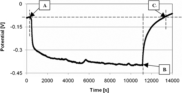
Evolution of potential as function of test duration for 3 h fretting test under 10 N load and 2 Hz of oscillation
On the basis of the determined characteristic points (Fig. 1), the indicators of repassivation time Irep (s) were calculated by means of the following equation

The results of the repassivation indicators obtained for various test durations are presented in Fig. 2.
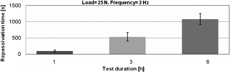
Repassivation time as function of test duration
As shown in Fig. 2, the time needed to rebuild the passive film after fretting stops is proportional to the fretting duration.
After each run, the test solution was removed from the holder by suction and analysed by means of inductively coupled plasma mass spectroscopy. The aforementioned method was used for determination of the Cr, Co and Mo ion concentrations in the test solution. Figures 3–5 show the levels of ions released to the test solution in relation to the test duration.
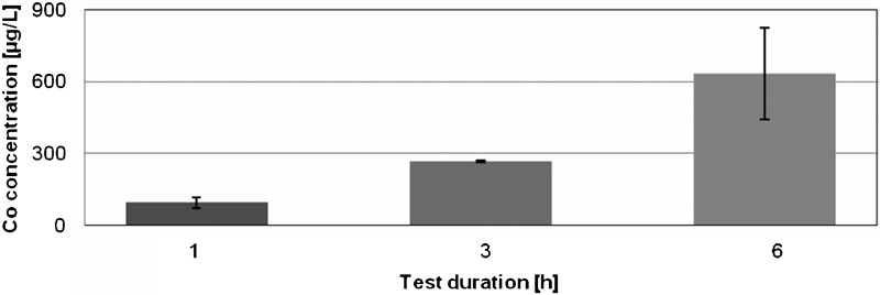
Co ion concentration in test solution as function of test duration
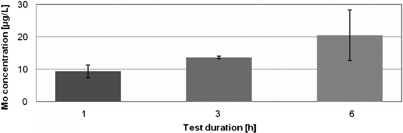
Mo ion concentration in test solution as function of test duration
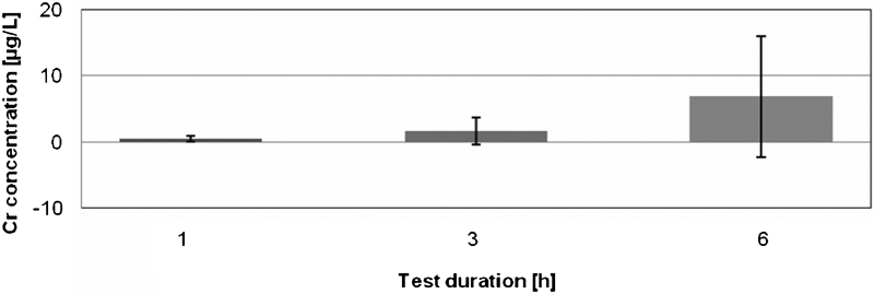
Cr ion concentration in test solution as function of test duration
The quantity of Co ions detected in the solution after fretting test follows a linear relation with the test duration.
The quantity of Mo ions released from the frictional interface increases in a proportional way with the test duration, although, in comparison to Co ion release results, in each case, the concentration was ∼30 times lower.
In the case of Cr ions, for longer tests, more ions were released, and also a larger spread of results was observed. The quantity of released ions is about five times lower than in the case of molybdenum.
After each test, the wear track on both specimens was analysed. However, only damage of the lower flat specimen was further considered due to almost no difference in wear of the upper specimen. A profilometer was used for determination of volumetric wear. In Fig. 6, measured volumetric wear is presented as a function of test duration.
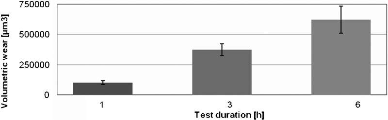
Wear volume as function of test duration
From the above results, it has been observed that the concentration of ions released into the test solution and the time of repassivation are in linear relationship with the test duration. Wear of specimens, which is increasing with time under the fretting corrosion conditions, is related to the increase in the surface area with damaged passive film, which is exposed to corrosion and ion release. As a consequence, the time needed for repassivation also increases. Owing to ambiguous results of Cr concentration (oscillating about zero, with very high results spread), the aspect of Cr transfer is not considered in further analyses.
Impact of normal load
Additional tests under 10 N load and 2 Hz frequency amplitude were performed to investigate ion release and wear behaviour of the tribocouple in the case representing 60 kg patient body weight. The results of tests performed under 25 N load were used as a reference point. The test results are shown in Figs. 7–9.
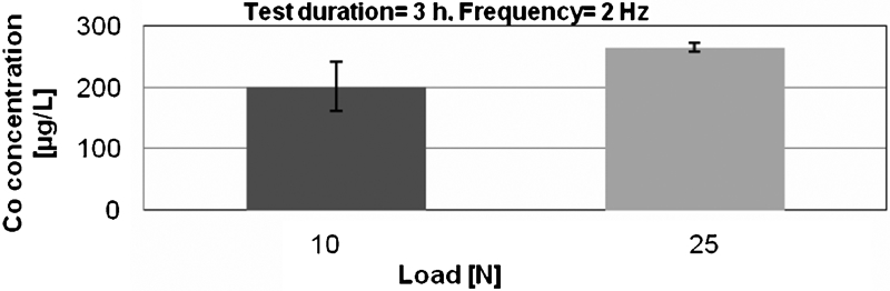
Co ion concentration as function of normal load
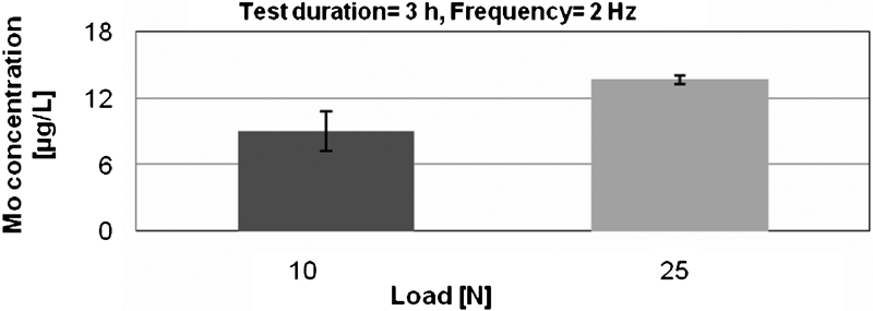
Mo ion concentration as function of normal load
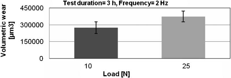
Wear volume as function of normal load
The obtained results show that a decrease in load caused a decrease in wear followed by lower levels of ions detected in the test solution.
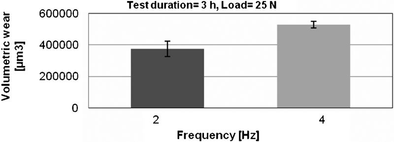
Impact of frequency
Additional tests under 25 N load and 4 Hz frequency were performed to investigate ion release and wear behaviour of the tribocouple in the case of increased intensity of patient activity represented by a higher motion frequency. The results of tests performed under 25 N load were used as a reference point. The test results are shown in Figs. 10–12.
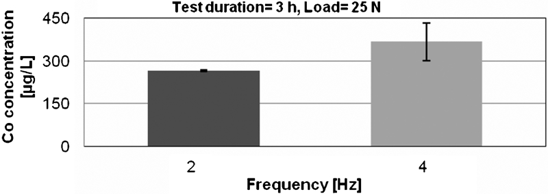
Co ion concentration as function of oscillation frequency
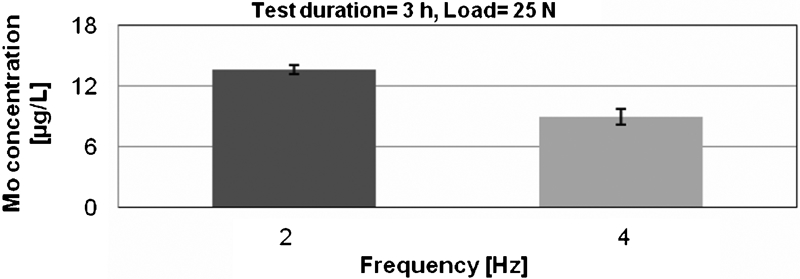
Mo ion concentration as function of oscillation frequency
Wear volume as function of oscillation frequency
The results obtained show that the test conditions of a higher intensity result in an increase in volumetric wear of the tested materials. Higher wear was followed by an increase in Co ion concentration of ∼30% in comparison with the reference case. On the other hand, higher oscillation frequency caused a decrease in Mo ion quantity transferred to the test solution. The aforementioned fact can be explained as a result of high ability of molybdenum to create a very hard passive layer, which, concerning the specimen composition (65·6%Co and 5·8%Mo), leads to higher wear and higher level of Co ion release.
Impact of added fretting pauses
To simulate changes in patient activity, additional tests were performed under variable loading conditions. A standard fretting test (3 h duration, 25 N of load and 2 Hz oscillation frequency) was divided into three 1 h active periods, where fretting action was taking place and separated by static periods without any fretting taking place. The graph showing an example of potential curve from one of these tests is presented in Fig. 13.
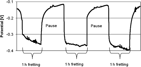
Potential curve showing 3 h test divided into three periods of fretting separated by static periods
The three durations of fretting pauses selected were 5, 30 and 60 min. Relationships between volumetric wear, ion concentration measured in the test solution and duration of fretting pause are presented in Figs. 14–16. As a reference point, results of fretting test without any static period are added.
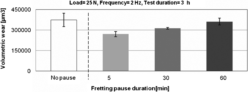
Wear volume as function of static period duration
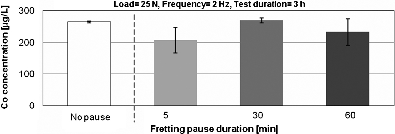
Co ion concentration after test with various pause durations
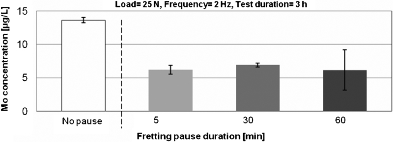
Mo ion concentration after test with various pause durations
The active fretting period (3 h) was the same for all three cases; however, for the test with the shortest fretting pauses, the lowest volumetric wear was observed. The wear obtained for the test with 1 h pauses between fretting periods showed similar wear as in the case of the reference test without any static period.
Static periods added to a standard fretting test do not influence much quantity of Co ions released at the frictional interface. In the case of Mo ions, there is not much difference in ion release levels between different static periods; however, comparing with the reference test, the quantity of ions released is approximately two times lower. A lower level of Mo ions detected in the test solution in that case can be explained by the ability of molybdenum to create a hard passive layer, which is accelerated by the pauses between fretting periods.
The obtained results show that only in the case of very short pauses added between fretting periods can the low decrease in wear be achieved (∼25%). In the case of longer pauses, wear and the release of Co ions stay on the similar level as in the reference test, although adding fretting pauses, regardless of their duration, caused significant decrease in Mo ion release. Independently of the pauses between fretting periods, the total number of fretting cycles in the aforementioned tests was the same.
Conclusions
Experiments under fretting corrosion conditions were performed on model ball on disc friction couple, simulating the head–neck taper joint of modular hip prosthesis. The problem approached in this paper was the effect of fretting corrosion, in particular the metallic ion release, wear, depassivation and repassivation time, dependence of fretting period duration, applied load and oscillating frequency. The following conclusions can be drawn.
The results obtained indicate that wear, increasing with the duration of fretting, causes an increase in the size of area exposed to the solution, resulting in the significant increase in ions released. This effect is confirmed by an increase in the time needed to re-establish the passive layer.
Tests performed under conditions simulating various patient body weights and types of activity show that a decrease in the friction joint load results in lowering both wear and ion release. It was also observed that intensification of fretting corrosion leads to an increase in wear of friction joint elements, while changing the proportions of ion release, which in reference to the human body, can lead to acceleration in the release of more toxic ions.
The results obtained for the fretting tests with added pauses show that the short pause duration between fretting periods can result in a decrease in friction joint wear followed by a decrease in the release of some ions.
The results show that the electrochemical aspect of fretting is an important problem, which needs to be further investigated, especially in the context of long term tests.