
Abstract
Zinc–aluminium alloys are known to possess excellent sliding wear properties particularly at a high load and low speeds. This paper investigates the effect of the addition of commercial master alloys Al–5Ti–1B and Al–5Sr to the melt with respect to the microstructures and unlubricated wear properties of a zinc–aluminium alloy. Along with the microstructural modification, the addition of the master alloys improves the bulk hardness and the wear resistance of the zinc–aluminium alloy. The wear behaviour of the alloys is explained on the basis of the microstructure, hardness and existing models of wear and friction.
Introduction
Zinc–aluminium (ZA) alloys, with a unique combination of properties, are competitive alternative materials to most aluminium casting alloys, bearing bronze, cast iron, as well as to plastics and steel fabrications.1–6 Zinc–aluminium alloys are a group of high performance, high aluminium zinc alloys with excellent bearing properties. 3 6 3,6,7 The present study investigates the unlubricated wear behaviour of ZA alloys containing minor quantities of Ti+B and Sr added as commercial master alloys Al–5Ti–1B and Al–5Sr respectively.
Abrasive wear occurs when a rough, hard surface containing hard particles slides on a softer surface ploughing a series of grooves in it. Wear by hard particles occurs in many different situations such as on earth moving equipment, slurry pumps or pipelines, rock drilling machinery, rock or ore crushers, equipment for pneumatic transport of powders, dies in powder metallurgy, extruders or chutes, etc.8 Increasing hardness of the material or decreasing hardness of the abrasive accelerates the transition from abrasion to sliding wear.9 It has been shown both experimentally and theoretically that the hardness of a material correlates with its abrasion rate. The wear resistance of the metal is found to be proportional to the hardness of the worn surface.10 Adhesive wear occurs when two smooth bodies slide over each other and fragments pulled off from one surface adhere to the other. Later these fragments may either come off from the surface on which they are formed and be transferred back to the original surface, or else form loose wear particles. 11 11,12
Microstructural refinement plays a significant role in enhancing the hardness of alloys. This approach has been used in the present investigation and the subsequent effect of microstructure on the unlubricated wear behaviour of zinc–aluminium based alloys has been studied. Commercial master alloys are commonly used for grain refinement of aluminium alloys. Similar alloys have been used as an additive in the alloy of the present investigation. Unlubricated wear is practically important for zinc–aluminium alloys and hence, all tests have been carried out in the dry condition.
Experimental
Alloys are prepared by conventional melting and casting route in the form of 16 mm square cross-section and 160 mm long castings. Casting is performed in cast iron moulds. For microstructural characterisation, samples are metallographically polished according to standard practices and etched suitably using diluted nitric acid (5 vol.-%) in water. The typical composition of the alloy is Al: 26–28%, Cu: 2·0–2·5%, Mg: 0·05–0·06% and balance: Zn. All compositions are given in wt-% unless mentioned otherwise. In addition to the above elements, 0·1% each of Ti and Sr have been added to the base alloy compositions, i.e. ZA1. Ti and Sr were added in the form of commercial master alloys, Al–5Ti–1B and Al–5Sr respectively. Bulk hardness of all alloys is measured using a Brinell hardness tester with a 10 mm diameter steel ball indenter and under a load of 500 kg. The application time of the load is 60 s. Worn surfaces are examined using scanning electron microscopy (SEM) attached with an energy dispersive X-ray spectroscopic facility. Abrasive wear tests are carried out on 16 mm square cross-section samples having a thickness of 8 mm, against 320 grit SiC (hardness: 2500 kg mm−2) paper affixed to a rotating flat disc of 250 mm diameter.13 The tests are carried out at 300 rev min−1 (3·925 m s−1) and 500 rev min−1 (6·54 m s−1) and under a constant load of 10·9 N. The total time of duration of the tests is 300 s, which corresponds to sliding distances of 1177·5 and 1962·5 m for the speeds of 300 and 500 rev min−1 respectively. Dry sliding wear tests are performed in a pin on disc type machine, on 8·5 mm diameter, 45 mm long cylindrical test specimens against a steel disc of hardness of 60 HRC. The schematic arrangement of the wear test set-up and the specimens used for the tests are shown in Fig. 1. The typical chemical composition of the steel (EN31 grade) is C: 0·9–1·2%, Si: 0·1–0·35%, Mn: 0·4–0·8% and Cr: 1·0–1·6%. The disc has a roughness of 0·4–0·6 μm. Rotating speeds used in the sliding wear tests are also 300 and 500 rev min−1, corresponding to sliding speeds of 2·2 and 3·7 m s−1 respectively. The load is varied from 200 to 1500 g. Wear rates are computed by the weight loss technique. A Sartorius make electronic balance was used for weighing the specimens. Before weighing, the specimens are cleaned with ethanol to remove the wear debris. For the abrasive wear tests, weight loss is measured at intervals of 30 s. Wear data have been plotted as weight loss per unit applied load per unit area of specimen surface as a function of time (s). For the sliding wear tests, at each load the weight loss is measured after running the sample for 2·5 and 4 min at 500 and 300 rev min−1 respectively. The times had been selected on the basis of prior experiments to determine the time of attainment of stability at each testing speed. In this case, wear data have been plotted as weight loss as a function of applied load. The worn surface of one of the alloys has been studied in a Fourier transform infrared (FTIR) spectroscopy machine in a Thermo Nicolet FTIR spectrophotometer (model: Nexus 870) to confirm the presence of ZnO formed during the sliding wear process. The FTIR scan is carried out by diffused reflectance spectroscopy. For the purpose of comparison, the polished surface of the alloy and pure ZnO are also subjected to FTIR scan.
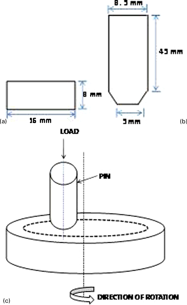
Schematic diagram of a, b specimens used and c test set-up for wear tests
Results and discussion
The authors have already reported results on the microstructural evolution of these alloys.14 Figure 214 shows the microstructural features of the alloys. The unmodified alloy, ZA1, reveals the presence of primary α dendrites, surrounded by the α+η eutectoid product in the interdendritic regions. ZTiB1 and ZSr1 show significant microstructural refinement (Fig. 2). It is evident from the micrographs shown in Fig. 2 that the addition of Al–5Ti–1B results in the formation of rosette shaped dendrites. The addition of Al–5Sr master alloy to ZA27 increases the curvature of the dendritic arms.
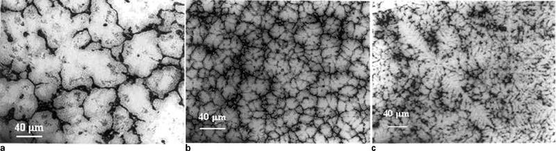
Optical micrographs of a ZA1, b ZTiB1 and c ZSr1 as cast alloys14
Intermetallic particles (Al3Ti, AlB10, Al4Sr, etc.) were present in the master alloys and did not undergo any change during the melting and casting of the zinc based alloys. The presence of these particles is evident from X-ray diffractogram of the master alloys shown in Fig. 3. These particles act as potential heterogeneous nucleation sites, increasing the rate of heterogeneous nucleation in the alloys ZTiB1 and ZSr1, thus resulting in finer microstructure in these alloys.
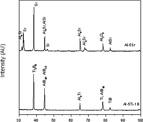
X-ray diffractogram of master alloys added to ZSr1 and ZTiB1
The bulk hardness of the alloys modified with Al–5Ti–1B and Al–5Sr undergoes significant improvement as compared to the unmodified alloy, ZA1, as shown in Table 1. The improvement in hardness is owing to the microstructural modification of these two alloys. According to the findings of Osorio et al., 15 15,16 in cast alloys, strength increases with decreasing secondary dendritic arm spacing. The hardness obtained for the cast alloys in the present investigation has been plotted against the secondary dendritic arm spacing as shown in Fig. 4. It is observed that the hardness increases with decreasing dendritic arm spacing.
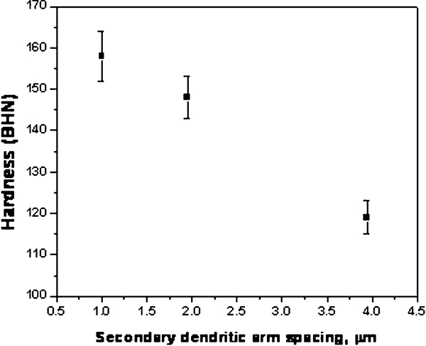
Variation of hardness with secondary dendritic arm spacing
Bulk hardness of as cast alloys
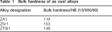
Figure 5 shows the effect of the addition of commercial master alloys (Al–5Ti–1B and Al–5Sr) on the abrasive wear behaviour of ZA27 based alloy. Abrasives fixed in place often become less effective in material removal as the sharp points fracture, wear and become coated. Additionally, the clogging of the paper by abraded particles generated from the material being abraded results in a drop in the wear rate.17 Therefore, the effectiveness of the abrasive paper in causing wear decreases with time. These effects are illustrated in Fig. 5, where the wear curves tend to flatten with increasing time. It is evident from Fig. 5 that abrasive wear loss is least for ZSr1, followed by ZTiB1 and ZA1 at both 300 and 500 rev min−1. Therefore, the wear resistance is highest for ZSr1 which has the maximum hardness, followed by ZTiB1 and ZA1 with lower hardness. It has been shown both experimentally and theoretically that the hardness of a material correlates well with its abrasion rate. The wear resistance of the metal is found to be proportional to the hardness of the worn surface.10 The higher the hardness of the softer component of the system, the less the depth to which the abrasive particles can cut/plough across the surface of the component. Hence, in the present case, the alloy containing Sr (ZSr1) suffers the minimum amount of wear loss owing to its maximum hardness. The worn surfaces of the alloys tested at 300 and 500 rev min−1 are shown in Figure 6 Figs. 6 and 7 respectively. The surface of ZA1 is marked by shallow grooves and less surface damage at the lower test speed of 300 rev min−1, corresponding to a relatively mild wear. The worn surfaces of ZTiB1 and ZSr1 are marked by occasional deep grooves in certain portions while the rest of the surface is covered with relatively shallow grooves, corresponding to the high wear resistance of these alloys. The surface of ZSr1 has a smoother appearance (grooves are shallower) than that of ZTiB1 in accordance with the lower wear loss suffered by this alloy at both the test speeds.
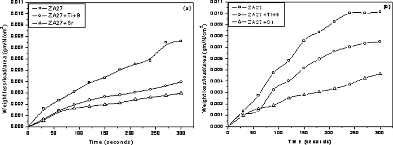
Effect of master alloys on abrasive wear behaviour of ZA27 alloy at a 300 rev min−1 (3·925 m s−1) and b 500 rev min−1 (6·54 m s−1)
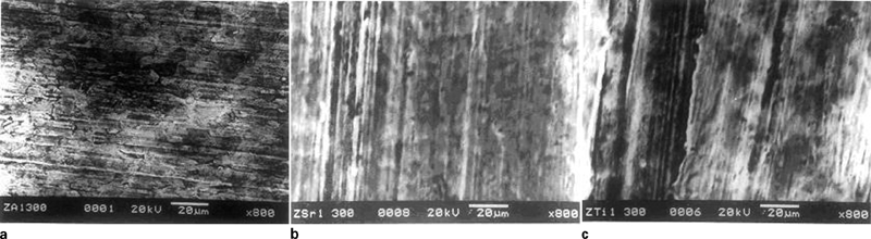
Images (SEM) of worn surfaces (abrasive wear tests) of a ZA1, b ZSr1 and c ZTiB1 at 300 rev min−1 (3·925 m s−1)
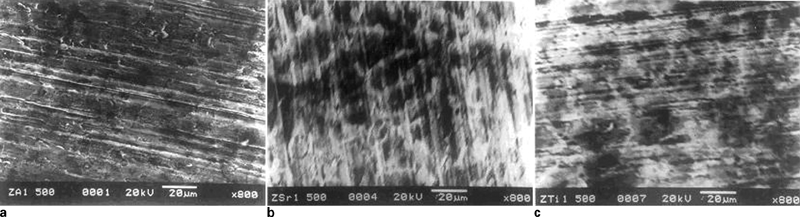
Images (SEM) of worn surfaces (abrasive wear) of a ZA1, b ZSr1 and c ZTiB1 at 500 rev min−1 (6·54 m s−1)
During wear ZnO forms on the worn surface of the sample. It is non-conductive. Therefore, the sample gets charged-up under the electron beam resulting in poor image quality. Image quality could be improved by a thin conductive coating of gold on the worn surface. However, this may cause some alteration of worn surface morphology. Therefore, as-worn samples without any surface preparation have been photographed and reported here, even though image quality is not good.
Figure 8 shows the effect of the addition of master alloys on the dry sliding wear behaviour of ZA27 alloy. For all the alloys, with an increase in applied load, weight loss initially increases which becomes nearly constant at higher loads. At 300 as well as 500 rev min−1, ZSr1 having the highest hardness suffers the minimum weight loss. This behaviour is in accordance with the Archard's wear equation, i.e. the wear rate is inversely proportional to the hardness of the material and directly proportional to the applied load and distance traversed.11 The mean surface temperature during sliding can be calculated using the formula18

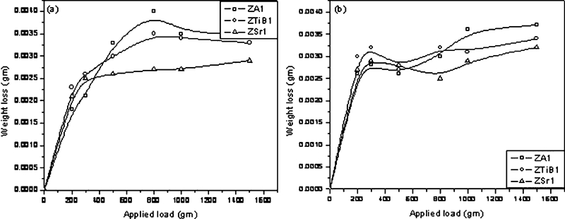
Effect of master alloys on dry sliding wear of ZA27 at a 300 rev min−1 (2·2 m s−1) and b 500 rev min−1 (3·7 m s−1)
The SEM images of the worn surfaces at 2·2 and 3·7 m s−1 are shown in Figure 9 Figs. 9 and 10 respectively. It is observed from these figures that for the alloys ZTiB1 and ZSr1, wear by ploughing mechanism (presence of grooving) occurs predominantly. On the other hand, adhesive wear is the dominant wear mechanism in the unmodified alloy, ZA1. During ploughing or grooving, some materials are lost in the form of chips or lumps, while other materials are pushed into ridges along the sides of the grooves.10 Delamination, on the other hand, results in the removal of material in layers. Hence, the latter mechanism causes higher wear loss than that during grooving. However, this is not always true and will depend on the relative depth of grooves or the thickness of layers removed by delamination. At the higher test speed, the surface temperature reached is higher, and hence the alloys are subjected to more severe conditions of sliding. However, the worn surfaces in Fig. 10 show that the wear mechanism remains same for all the alloys. The minor increase in wear loss at 3·7 m s−1 is due to the increase in surface temperature as compared to that at 2·2 m s−1.
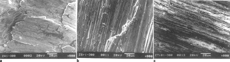
Images (SEM) of worn surfaces (sliding wear) of a ZA1, b ZSr1 and c ZTiB1 at 300 rev min−1 (2·2 m s−1)
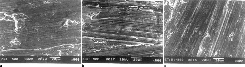
Images SEM of worn surfaces (sliding wear) of a ZA1, b ZSr1 and c ZTiB1 at 500 rev min−1 (3·7 m s−1)
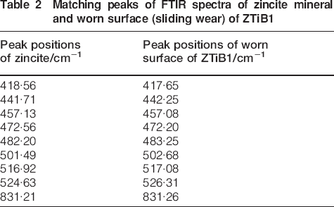
Figure 11 shows the effect of microstructural modification on the frictional behaviour of the alloys. It is observed that the modified alloys with a higher hardness have a lower coefficient of friction (COF) than the unmodified alloy at 2·2 m s−1. However, the improvement in hardness has no significant effect on the COF at the higher speed. With increasing load and hence increasing surface temperature, an increasingly adherent film of ZnO is formed on the surface of all the alloys. The ZnO film acts as a soft lubricating phase effectively reducing the COF. The results of FTIR study of the worn surface of a sample are shown in Fig. 12 and Table 2. It is evident from Table 2 that the positions of many of the peaks have been found to match well with the standard spectra of zincite mineral (chemical composition: ZnO). Therefore, it has been experimentally confirmed that ZnO is formed on the surface of the alloys during sliding wear process. As the abrasive mode of wear increases with increasing speed (Fig. 10), the COF of the modified alloys also increases significantly with the test speed. The energy of deformation represented by the grooves on the worn surfaces of the modified alloys must be supplied by the friction force, which therefore is larger than that in the absence of grooves. With an increase in speed, the wear mechanism remains unchanged in ZA1 and therefore only a small change is noticed in its COF.
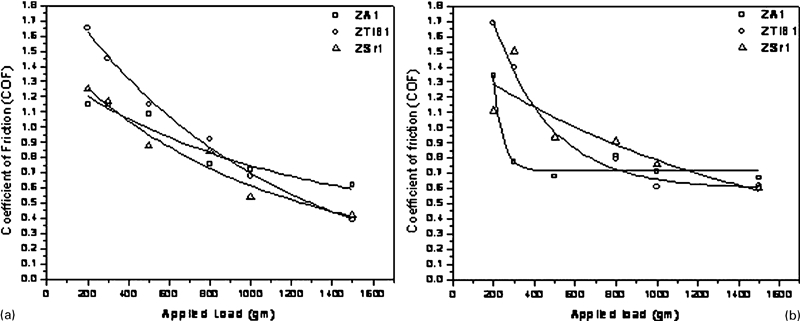
Effect of master alloys on COF during sliding wear at
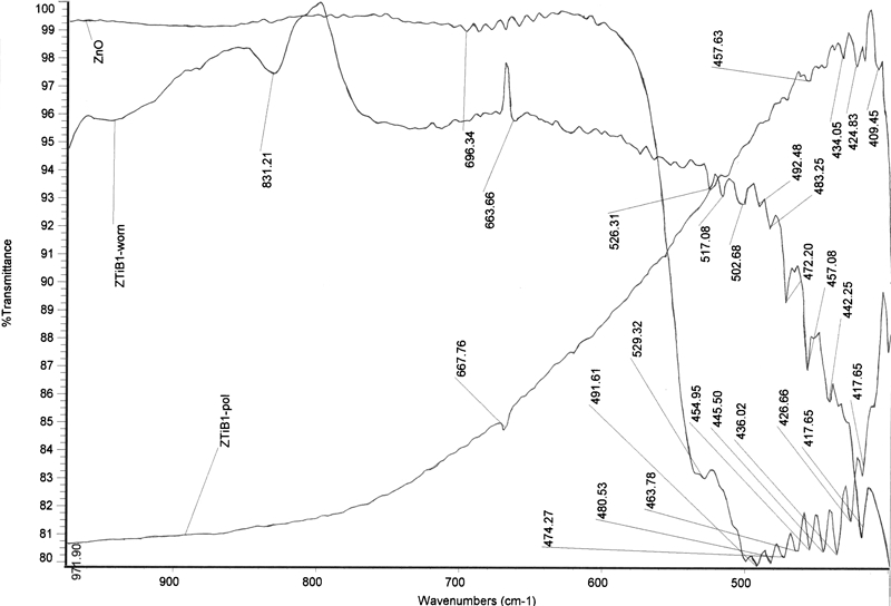
Fourier transform infrared spectra of worn and polished surfaces of ZTiB1 compared with that of ZnO
Matching peaks of FTIR spectra of zincite mineral and worn surface (sliding wear) of ZTiB1
During sliding, simultaneous processes of adhesion and deformation occur, and the COF19

For plastic contacts

Wad = 0·124 N m
Conclusion
The addition of master alloys commonly used for grain refining of aluminium alloys is effective in significantly modifying the microstructure of a high aluminium, zinc based alloy. The microstructural modification leads to a rise in the bulk hardness of the alloys. The higher bulk hardness of the modified alloys significantly improves the abrasive wear resistance. At both the test speeds, an improvement in sliding wear resistance is observed with increasing hardness. It has been shown that with increasing speed, abrasive mode of wear becomes dominant in the modified alloys. With increasing load, an increasingly adherent film of ZnO is formed on the surface of the alloys. ZnO acts as a dry lubricant and hence it is effective in reducing the COF with increasing load. The COF is lower for the harder alloys at the lower speed. However, owing to the predominance of abrasive wear in the modified alloys at the higher speed, the COF of these alloys undergoes a significant rise, while that of the unmodified alloy remains nearly same.
Footnotes
Acknowledgements
Financial support received from the Defence Research and Development Organization, Department of Defence Research and Development, Government of India to carry out this research is gratefully acknowledged.