
Abstract
In this paper, we present the design of a novel microtribometer operating in ultrahigh vacuum. The force sensor of the tribometer is based on the double leaf cantilever design. To remove noise and mechanical deformation due to temperature oscillation from measured signals, we employ a double laser interferometer and a passive noise reduction system. Depending on the spring constant of the cantilever used, the detection limit of lateral force measurements ranges from a few micronewtons to 1 mN. The tribometer chamber is equipped with an e-beam evaporator for deposition of metallic thin layers. The instrument is also connected to an X-ray photoelectron spectroscopy system. In the remainder of this paper, we present an experiment conducted on thin silver films that involves all of the components mentioned above.
Introduction
The market of mechanical components operating in vacuum (aerospace applications, lab instrumentations, etc.) is in continuous evolution, demanding new technologies and new solutions to tribological problems.1 At the same time, the tribological behaviour of materials in vacuum can be completely different from what is observed in air. A well known example is graphite. Graphite works well as a lubricant in air, but it shows a much higher friction coefficient in vacuum.2 Therefore, research conducted on the tribological behaviour of materials in vacuum has lead to the construction of different vacuum tribometers.
Depending on their purpose, location and force working range (from nanonewtons to newtons) vacuum tribometers have different designs.1,3–7 They may be placed in complicated and large vacuum set-ups with several surface analysis techniques implemented in a single chamber.3,4 Those chambers need to be connected to vacuum pumps in order to maintain a specific pressure, which is usually a source for noise and vibrations. A unique exception was recently presented by Krick and Sawyer who achieved to operate a dedicated tribometer in space.1
Owing to their different design, tribometers have different force detection systems like strain gauges,3,6 laser interferometry (like the tribometer presented in this paper)5 and microelectromechanical systems.7
Each force detection scheme has advantages and disadvantages. For example, strain gauges need a bending cantilever directly connected to the pin and electric feedthroughs placed in the ultrahigh vacuum (UHV) chamber to collect electric signals, while a laser interferometer needs a reflective surface fixed on the cantilever and can work from outside the chamber through a UHV window.
Microtribometers equipped with laser interferometers that are located outside the UHV chamber, however, suffer from induced vibrations. Besides, due to the relatively long optical path of the lasers, a change of temperature will cause a measurable expansion or compression of the vacuum chamber steel walls. The problem of induced vibrations cannot be solved unless the entire UHV chamber, as well as the detection system, is installed on an antivibration system. In fact, the application of an antivibrating system inside the UHV chamber would complicate the design of the machine and exponentially increase the handling problems. At the same time, the detection device outside the UHV chamber would still be exposed to noise; therefore, a second noise protection system would be requested. Placing the entire system in a temperature controlled housing can solve the issue of temperature induced deformations. Unfortunately, this solution is sometimes inconvenient or even technically impossible.
In this article, we show how to use a double beam laser interferometer in order to eliminate both of the above mentioned problems from the lateral force signal for UHV microtribometry.
Tribometer chamber and X-ray photoelectron spectroscopy (XPS) system
The microtribometer presented here is placed in the centre of a DN100 UHV six-way cross (Fig. 1). The chamber is connected to the introduction load lock of a ‘PHI 5000 Versa Probe’ XPS system (Physical Electronics). A UHV valve isolates the tribometer's UHV chamber from the high vacuum introduction chamber.
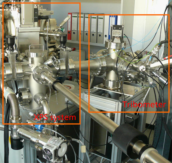
Overview of tribometer chamber (six-way cross 100DN on right side of picture) connected to introduction chamber of PHI XPS system
The remaining flanges of the six-way cross are used for windows (for interferometer's laser beams), tribometer flange, e-beam evaporator and pumping system.
Ultrahigh vacuum in the tribometer chamber is achieved by means of a 150 L s−1 titan ion pump (Gamma Vacuum). Although the ion pump does not generate vibrations, some vibrations caused by the XPS couple to the tribometer. Vacuum obtained with this system is about 10−7 Pa without bake-out.
Tribometer design
In Fig. 2, a schematic of the design of the tribometer is presented. The cantilever is fixed, while the sample is scanned by means of a piezo stage. The stage is a UHV compatible PiezoJena TRITOR 100 stage (piezosystem jena GmbH). It can move in three dimensions with a range of 110 μm on each axis (Fig. 2).
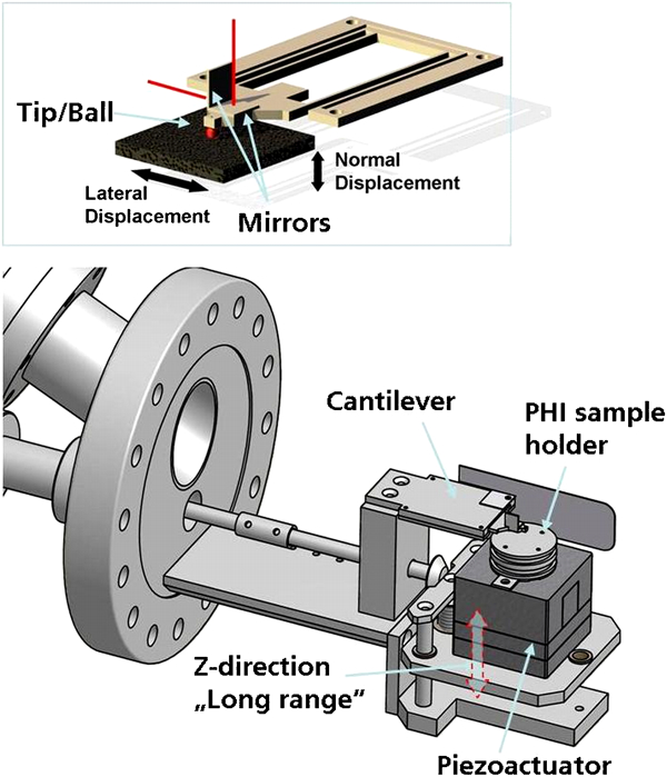
Schematics of microtribometer: top, double leaf cantilever sketch; red lines are laser beams hitting mirrors on cantilever, and black arrows show movement of piezoactuator; bottom, tribometer sketch; red dashed arrow shows vertical movement of shelf of piezo driver; movement is transmitted to shelf via rotary feedthrough
Our instrument revolves around the double leaf cantilever concept presented by Scherge and Gorb.2 Owing to its peculiar design, this cantilever does not show friction force induced torsion, e.g. atomic force microscopy (AFM) cantilevers. The cantilever bending in vertical direction due to applied load stress is also strongly reduced. Therefore, it is possible to measure the cantilever displacement by means of interferometers. For this purpose, the cantilever is equipped with two mirrors (one horizontal and one vertical).
The stage of the microtribometer is designed to be compatible with PHI sample holders (Fig. 2), so the sample can be moved from the tribometer to the XPS system without being exposed to air. In order to obtain this combination, we placed the piezo stage of the tribometer on a base that can be moved up and down by 35 mm (Z direction ‘long range’ movement in Fig. 2). This movement allows us to take the sample from the manipulator and the other vice versa without the need of a wobble stick. To be able to obtain a precise and reliable displacement from outside the UHV chamber, we combined a rotary feedthrough to a moving screw via conical gears (see Fig. 2). The shelf is therefore moved by the screw and guided by vertical shafts.
The long range movement of the piezo shelf is also necessary to bring the sample near the counterpart glued to the cantilever. The piezo stage's vertical movement provides the last few micrometers. Nanometric movement is indeed necessary to obtain a soft approach and to apply the requested normal load in the micronewton range. The movement of the stage is controlled using a dedicated LabView program.
Tribometer: Laser interferometer and noise reduction system
Laser interferometer
As already mentioned, the displacement of the cantilever is measured by means of laser interferometry. We use two SIOS laser units (SIOS SP 120) (SIOS Meßtechnik GmbH) for normal and for lateral force detection.
Each unit is equipped with a LA-03 laser output module incorporating a single He–Ne laser (wavelength, 633 nm). One unit has a single laser beam output module, while the second one has a double beam output module (single laser source with a Y coupler).
The lasers are coupled to the modules via optical fibres.
The environment temperature and pressure stabilisation of the laser is obtained by means of a UW-02 temperature/pressure correction module equipped with a barometric pressure sensor.
The single beam module is placed in vertical position on the UHV chamber's top flange (Figs. 1 and 3) in order to measure the vertical displacement of the cantilever (applied load), while the double beam laser head is placed horizontally on the side of the chamber to measure lateral displacement of the cantilever (friction force) as shown in Fig. 3.
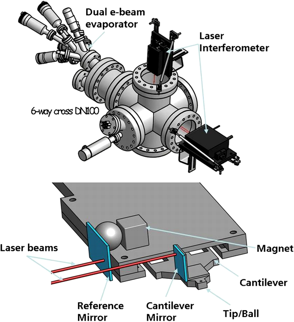
Top: position of laser interferometer devices; red lines indicate lasers. Vertical laser measures applied load, while double horizontal laser measures friction force. Bottom: ‘noise subtraction’ double interferometer system. One mirror is glued on cantilever and detects displacement stemming from frictional forces. Second mirror on cantilever holder can be aligned with respect to first one by rotating steel (to which mirror is glued) ball against magnet. This allows aligning both mirrors. Subtracting reference signal from cantilever signal, we are able to obtain ‘drift free’ and ‘low noise’ friction force output. Final noise amplitude is ∼10 nm
The laser interferometry yields a very high accuracy and resolution (0·1 nm) but at the same time poses an upper limit to the displacement range. In fact, the laser interferometer needs the reflected laser beam to be aligned to the outgoing laser beam (only a small angle up to 2° is allowed). Owing to the cantilever design, the tilt in the friction force direction is negligible (in the force range for which this instrument has been designed), while in the vertical direction the cantilever bending under stress (applied load) is reduced but not completely removed. The tilt can exceed 2°. As a consequence, the applied load limit is a function of the spring constant of the cantilever, the cantilever design, and the pin dimension and shape. The limit of applied load is roughly in the order of 1·8±0·3 mN, with the cantilever spring constant in the range of 20–200 N m−1.
Laser shelves
The two laser units are positioned on movable shelves (Fig. 3): a vertical shelf on the top of the six-way cross (applied load measurement) and a horizontal on the side of the chamber (friction force). Since the position of the reflecting mirrors changes every time the cantilever is replaced, it becomes necessary to have adjustable laser housing. The laser head itself has a fine adjustment system (screw driven), but the movement range is limited and it only changes the angle of the beam direction. Therefore, the adjustment of the units is necessary for a first rough positioning of the laser beam on the mirrors (changing height and lateral position of the laser units), and then the fine movement is used for final positioning.
Noise reduction system
As discussed in the previous sections, the instrument consists of different parts and it is directly connected to an XPS instrument. Mechanical noise stemming from the XPS is therefore affecting tribometer measurements.
For this reason, a noise reduction system has been implemented to enhance the sensitivity of the friction force signal. We use a double beam interferometer to distinguish the friction signal from mechanical vibrations and thermal drift. One beam is focused on the cantilever (mirror 1) and detects the displacement of the spring during measurements. The second beam is focused on a static reference mirror (mirror 2) placed near the cantilever (Fig. 3, bottom). The distance between mirror 1 and 2 is a few millimeters. In Fig. 4, an example of noise reduction procedure is shown.
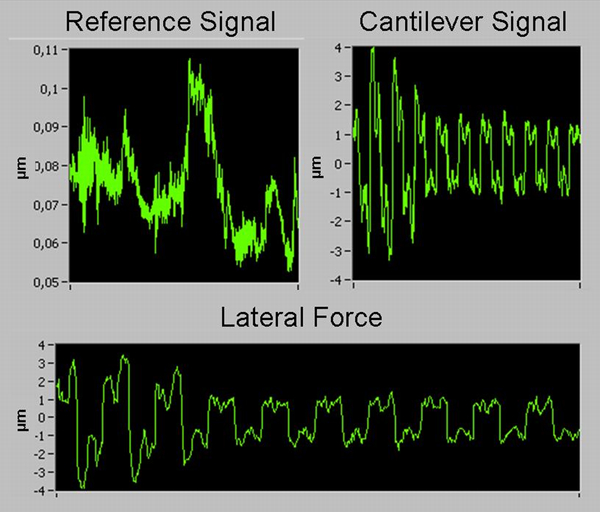
Example of noise reduction procedure: ‘reference’ signal is subtracted from cantilever signal, giving us low noise lateral force signal
The laser beam focused on mirror 1 measures the distance [x(beam1)] that is a combination of xA, which is displacement of the cantilever due to friction force (nm to μm range); xB, which is the vibration, measured on the cantilever, induced by external mechanical noise (nm); xC, which is the expansion/contraction of the components due to temperature oscillation that causes an expansion/contraction of the laser path (μm); and xD, which is the laser shelf vibration induced by external mechanical noise (nm to μm range).
The laser beam focused on mirror 2 collects a signal [x(beam2)] that is a combination of xE, which is the vibration induced by external mechanical noise as measured on mirror 2, which is fixed at the tribometer structure (nm); xC, which is the expansion/contraction of the components due to temperature fluctuation (expansion/contraction of the laser path); and xD, which is the laser shelf vibration induced by external mechanical noise.
According to the above, when subtracting the ‘reference signal’ [x(beam2)] from the cantilever signal [x(beam1)], we have
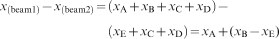
where xB–xE is the residual vibration of the tribometer (nm range). This noise sets the minimum friction force value that we can measure with our tribometer.
Converted to lateral force

The main technical problem in realising a double beam set-up is the alignment of the two mirrors. The two beams of the laser are perfectly parallel when they come out of the interferometer unit, and they must be parallel when they come back after reflection. Since the cantilever is fixed in its position using screws, it has a slightly different position every time we change it. Furthermore, the mirror on the cantilever is glued, so it is technically impossible to use different cantilevers with the same alignment.
For these reasons, we are obliged to avoid any kind of static design for mirror 2. This mirror must be rotatable in two axes in order to obtain parallel reflected laser beams after installing the cantilever.
For this purpose, we use a cubic NbFeB magnet and a metallic sphere that forms a minigoniometer similar to the mirror design of the vacuum AFM/STM produced by Omicron (Omicron NanoTechnology GmbH).
As shown in Fig. 3b, the cubic magnet is placed near the edge of the cantilever holder, while the sphere is kept in position by it and the edge of the cantilever holder. The second mirror is glued to the sphere. With this design, we are able to manually set any requested angle for mirror 2, so we can achieve an almost perfect alignment of the laser beams. The magnet is strong enough to keep the mirror in position.
As discussed before, pumps and other devices are sources of continuous vibrations that are transmitted to the laser shelves and via the chamber to our tribometer. The amplitude of oscillations produced by environmental vibrations is much higher at the position of the laser shelves (suspended mechanical system connected to chamber's flanges) than on the cantilever of the tribometer itself (cantilever is screwed to a stainless steel structure strongly fixed to the UHV chamber). A second source of fluctuations of the signal is the thermal expansion of the system. Because of the tribometer design and the long path between the detector and the mirrors (in terms of number of steel components in between), the thermal length fluctuations of the laser paths can clearly be detected. All of what described above is clearly visible when the tribometer is in standby position (cantilever is free to oscillate). The collected signals from mirror 1 and 2 are almost equal in noise and thermal drift, proving that all this is actually an external structural problem transmitted directly to the laser head. Yet, they are strongly reduced before reaching the cantilever. Therefore, the vibrational noise we measure is the vibration of the laser head mainly. The thermal deformation affects only the laser path. Low levels of noise on the cantilever are still present, but this noise has a different amplitude and frequency from the ones of the laser (measured on the fixed mirror); hence, the noise reduction system has no effect. With the noise reduction system on, the vibrational amplitude of the signal is about 10 nm peak to peak.
In light of the considerations that we have shown up to this point, the range of measurable movement of the cantilever in the friction force direction is wide. The lower limit is about 30 nm, while the upper limit (as described previously) is so high that the instrument cannot reach it during operation. Therefore, depending on the spring constants, it is possible to measure friction forces in the nanonewton range.
Owing to the lack of a noise reduction system, the vertical cantilever displacement (applied load) is limited: from 500 nm to 10 μm. The lower limit is due to noise (no noise reduction on vertical beam), while the upper limit is related to the operation of the laser interferometer (see above). In terms of force, this range can be shifted by changing the spring constants of the cantilever, but due to the noise level, it is impossible to measure in the nanonewton range when the XPS system is running. Considering the high cost and lack of necessity for a double beam laser system on the vertical axis, it was omitted in this construction. The normal load is indeed applied shortly before starting the experiment. After that, vibrations or a thermal expansion of the chamber will not compromise the real value (constant along the entire experiment) of the normal force.
E-beam evaporator
The tribometer chamber is also equipped with a Tectra E2 dual electron beam evaporator (Figs. 1 and 3) (Tectra GmbH). This device is used to produce metallic thin films on surfaces. The presence of a flux monitor system enables the evaporator to keep the metal ion flux constant. The system is currently used for silver film production and regulated on a deposition rate of 0·25 nm min−1, but the presence of two evaporation beams gives us the possibility to produce binary metallic multilayer (or mixed) coatings.
The evaporator flux is centred on the lowest position of the shelf. In other words, the shelf of the piezo stage (and therefore the sample) must be brought to the lowest possible position in order to achieve a good and reliable film deposition. This design and the presence of a shield (Fig. 2) on the side of the cantilever holder avoid contamination or accidental deposition on the pin and on the cantilever. The shield also protects the side window of the chamber from being completely metallised (the friction force horizontal laser would be reflected back from the metallised window without reaching the cantilever mirrors).
Test measurements
In order to test the system, we performed an analysis of the tribological behaviour of thin silver layers deposited on silicon. It is known that in particular conditions (e.g. space applications), liquid lubricants are not applicable and a solid substitute has to be applied. Silver belongs to the family of solid lubricants, and it is widely employed in sliding contacts. Goto et al. have thoroughly investigated the behaviour of silver thin films under UHV in recent works.3,9 A specific sample preparation recipe and a very low surface roughness of the counter surface (diamond pin) led to a measured friction coefficient of about 0·007.
A similar experiment was performed in our instrument. The complete description of the experiment and the results will be presented in another paper.10 In this context, we will just show part of the experiment.
For this experiment, we used a ruby ball as slider [in contrast to a diamond (111) pin as Goto et al.3,9]. The diameter of the ruby ball was 1 mm. The surface roughness (measured by means of AFM) had an rms roughness of 11 nm on a scale of 5 μm.
The substrate was Si(111). We did not perform a high temperature annealing to obtain the 7×7 reconstruction of the silicon surface after the sputtering. Indeed, after sputtering (argon ion sputtering on the XPS system) the substrate to remove the oxide layer, we moved the sample to the tribometer chamber and we performed a 10 min deposition of silver (by means of the e-beam evaporator). With the used set-up, the deposited layer reached a thickness of about 2·5 nm (measured by means of AFM at the end of the experiment).
Friction tests were then performed. The applied load was 1 mN, and sliding speed was 16 μm s−1. Each friction experiment consisted of a sequence of 30 reciprocating cycles on the same track at constant applied load. The sliding length was 100 μm. The friction coefficient was determined as the average of the lateral force over one complete cycle divided by the applied load. All data gathered from 10 μm in the beginning and the end of the track were neglected, as they correspond to the transition from static to kinetic friction and not sliding.
The exact same test was performed on bare Si(111). The result is shown in Fig. 5.
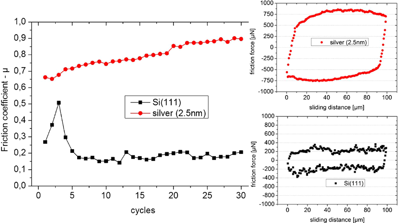
Friction tests performed on Si(111) sample and on thin silver layer with thickness of 2·5 nm deposited on Si(111). Left: friction coefficient evolution of Si(111) (black square) and of silver film (red circles). Every point was determined as average of lateral force over one complete cycle divided by applied load. Piece of about 10 μm of data has been cut off beginning and at end of each track in order to omit data from transition from static to kinetic friction. Right: friction loops from two friction tests (cycle number 20)
It is noteworthy that there is a clear difference between the friction data acquired from the two surfaces. On silicon, after an initial spike, friction reaches a stable value of ∼0·2. The first peak can be attributed to a thin layer of water/contaminants molecules on the surface of the ruby sphere.
On silver, the behaviour of the friction coefficient is completely different. It starts at about 0·65 and it keeps rising until 0·9 in the end of the test. From the reported friction loops, it can be seen that the noise in the measurements is far below (more than one order of magnitude) the value of the measured friction force.
After the friction tests on silver, the sample was moved back to the XPS system to analyse the wear tracks. The XPS results are reported in Fig. 6.
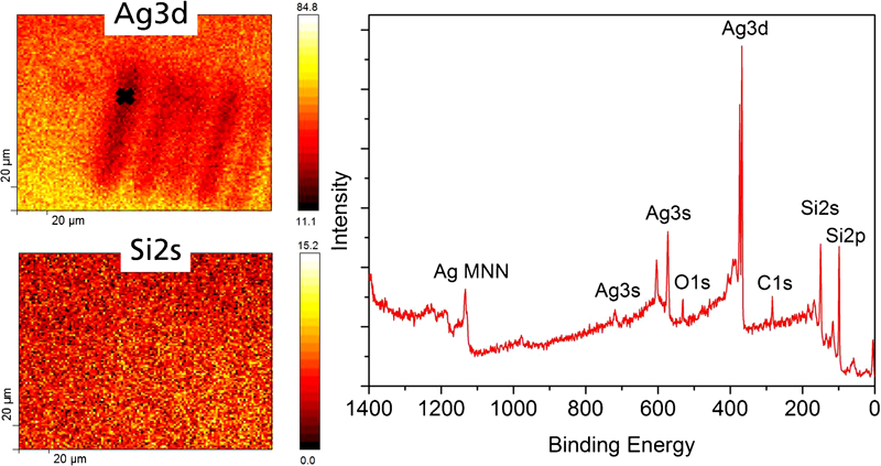
XPS analysis of wear tracks. Right: chemical mapping of wear tracks. X-ray beam diameter for this analysis was 10 μm. One hundred and twenty-eight points per line were acquired. Two maps show content of silver (Ag3d peak) and silicon (Si2s peak). Wear track obtained with 1 mN of applied load is one at extreme left of group. Left: full spectrum of indicated wear track (collected in position marked by cross in Ag3d map). All peaks related to surface composition are visible
A mapping of the wear tracks’ area was performed. For this purpose, the two main peaks Ag3d and Si2s were used. For mapping of surfaces, the X-ray beam was set to a minimum diameter of 10 μm. On the top left side, the ‘silver map’ is shown and five tracks are clearly visible. It is clear that silver was partially removed during friction tests. The different intensity of the silver signal in different wear tracks is due to the fact that different applied loads were used (as reported by Marchetto et al.10). The test performed at a normal load of 1 mN reported in Fig. 5 corresponds to the wear track at the extreme left of the group. On the bottom left corner of Fig. 6, a map created by the signal of Si 2s is shown. Here, the wear tracks are not so clear. Only a brighter area is visible in the same position where tracks are located. This is due to the fact that the signal of silicon is detected through the silver thin film (only 2·5 nm thick).
On the right side of Fig. 6, a full spectrum of the spot marked by a cross in Ag map is shown. The spectrum was obtained using a spot size of 10 μm in order to minimise the contribution of the surface outside the wear track. The presence of both silver and silicon is evident. The high concentration of silicon in the measurement indicates a partly removal of Ag within the track. The amount of the damage cannot be quantified from this spectrum. The silver signal may originate either from the area around the wear track since the wear track is smaller than 10 μm or from patches of silver film left in the wear track. Also, a small peak of oxygen and carbon is visible. This contamination could come from the silver deposition process.
The behaviour of the silver film explains the rise of the friction coefficient. While on silicon the contact between the ruby sphere and the sample is ‘clean’, on silver we have an interlayer that constantly changes during the experiment.
A complete description of the behaviour of the Ag film is provided by Marchetto et al.10 In this context, it is worth to notice that the friction coefficient measured on silver is much higher than what Goto et al. found.3,9 The explanation might be found in the high roughness of our sliding pin, which is about five times higher than the roughness of the pin used by Goto and could also be due to different deposition procedure. We speculate that due to the high roughness of the ruby pin, the asperities may penetrate the silver layer and reach the substrate, while the lack of annealing steps may also lead to a different nanostructure of the silver layer that does not provide any superlubric behaviour.
Conclusion
A UHV tribometer equipped with a noise reduction system has been developed. It is a double leaf cantilever tribometer. The displacement of the cantilever during measurements is measured via He–Ne laser interferometers (wavelength, ∼633 nm).
The movement of the sample is obtained by means of a piezo scanner (100 μm of maximum displacement) in three dimensions (XYZ).
The noise reduction system (working on the lateral force signal) reduces noise to a few nanometres. Therefore, the instrument can measure friction forces in the nanonewton range. On the contrary, the vertical signal (applied load) does not have any noise reduction module; therefore, the lowest measurable applied load is (according to spring constant of the cantilever) in the micronewton range.
The instrument is connected to an XPS system, and the transfer of samples from the tribometer to the XPS can be performed without any contact with the external environment.
Finally, the tribometer chamber is equipped with a double e-beam evaporator for in situ thin metallic films deposition.
An analysis of the friction coefficient of a thin silver layer deposited on silicon was shown. The system was successfully used to perform friction tests at microscale range and then chemically analyse the wear tracks. We can conclude that the combination of a UHV microtribometer (with low noise value), e-beam evaporator and XPS (equipped with ion gun) constitutes a valuable tool for the investigation of tribological behaviour of surfaces in vacuum.
Footnotes
Acknowledgements
This work has been supported by the Deutsche Forschungsgemeinschaft DFG (grant no. DI1494/2-1) through the EUROCORES programme FANAS AFRI of the European Science Foundation.
This paper is part of a special issue on Enabling and Emerging Lubrication Technologies