
Abstract
Many heavy duty components or particularly exposed surfaces in automotive applications are coated with diamond-like carbon (DLC). In this paper, two DLC coatings with different top layer chemistries were tested in various fuels to investigate how the chemistry impacts the tribological properties. A multilayer DLC coating with a softer tungsten doped top layer was compared to a DLC coating designed for automotive applications. The coatings were tested in different fuels under boundary lubrication conditions. The top layer containing tungsten was shown to enable the formation of WS2 in the contact when sliding in diesel and FAME. The process involves extraction of sulphur from the fuel and chemical reaction with W and transfer to the counter surface. Results are shown from SEM, Raman, XPS and TEM. The presence of WS2 was shown to coincide with a reduction of the counter surface wear as well as the friction.
Introduction
There is a continuous strive towards reducing energy consumption, reducing the environmental impact and increasing life time of mechanical components. Today these are very important factors in the design of new tribological systems for automotive applications.1
Many heavy duty components or particularly exposed surfaces are coated with diamond-like carbon (DLC) for protection and to improve the overall tribological performance.2,3 These coatings are often hard and chemically inert, with great wear resistance in most lubricated environments. To further reduce the friction, and thus the energy consumption, a more responsive surface is required, e.g. to get beneficial reactions with the additives.
In a previous study on the tribological behaviour of DLC coatings in contact with fuels, it was shown that the behaviour of the DLC coatings may vary significantly between different fuels.4 In that study, all DLCs had a similar top layer, a-C:H, but different layer structures underneath. The test conditions were harsh, with high contact pressure, and when wear occurred, the layers underneath the top layers, with different chemistry, were sometimes exposed. This resulted in new chemical environments, sometimes showing beneficial properties and sometimes detrimental effects. On engine components, the contact pressure is often low, due to conformal contact situations. Then the hard DLC coatings normally show very low wear. However, when critical components are coated with these types of hard coatings, the wear of the countersurface is sometimes aggravated. It has therefore become important to design coatings that combine a good wear resistance with the property of being gentle to the countersurface.
Other work has shown that when running a tungsten doped DLC coating against steel in contact with engine oils, a friction and wear reducing layer of WS2 may form on the steel surface, by a reaction of tungsten from the coating and sulphur from the oil additives.5,6
In this work, two DLC coatings with different top layer chemistries were tested in various fuels to investigate how the chemistry impacts the tribological properties. A multilayer DLC coating with a tungsten doped top layer was chosen. The tungsten may increase the reactivity of the surface and further there is a possibility that a thin tribofilm of WS2 may form by extracting sulphur from the fuel, in a similar way to that reported by Podgornik et al.6 This tungsten containing top layer was designed to be softer, so that a milder running-in with less wear of the countersurface could occur. This coating, hereafter called DLC W, was compared to a well performing DLC coating designed for automotive applications, with a harder top layer, hereafter called DLC C.
The tribological performance of the two DLCs was tested in different fuels under boundary lubrication conditions in room temperature. Focus is set on the interactions between the surfaces and the fuels and how these influence the friction and wear.
Materials and methods
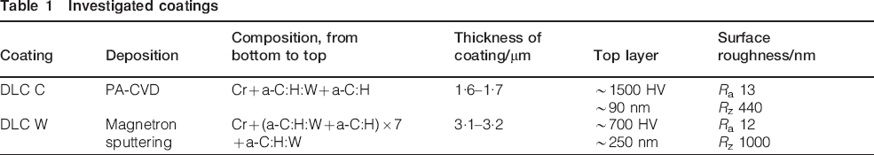
The DLC coatings were deposited on polished ASP 2023 High speed steel, hardened and annealed to 700 HV. The hardness of the top layers was measured with nanoindentation using a Berkowich diamond tip to an indentation depth of 30 nm and calculated using the method by Oliver and Pharr.7 A layer of chromium was first deposited on the steel to improve the adhesion. The double layered DLC C coating was then deposited by plasma assisted chemical vapour deposition. It consists of two layers; a tungsten doped hydrogenated amorphous carbon layer (a-C:H:W) and at the top a ∼90 nm thick layer of hydrogenated amorphous carbon (a-C:H). The multilayer coating (DLC W) was deposited with unbalanced magnetron sputtering and had a stacking of a-C:H:W followed by a-C:H alternated seven times and at the top a ∼250 nm thick a-C:H:W layer. More information about the coatings is found in Table 1. Cross-sections of the coatings can be seen in Fig. 1.
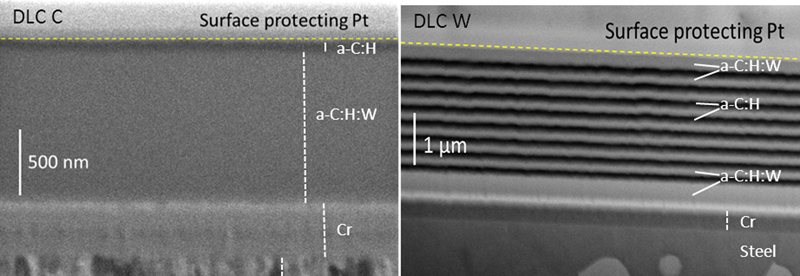
Cross sections of the DLC coatings. Left: The top layer of a-C:H for DLC C is about 90 nm. Right: The multilayer DLC W has a thicker top layer, about 250 nm, containing a-C:H:W
Investigated coatings
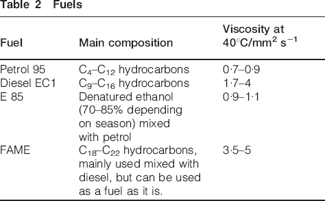
The coatings were tested in four commercially available fuels, see Table 2.
Fuels
The tribological testing was performed in a reciprocating ball-on-flat equipment. A 100Cr6 bearing steel ball with a hardness of 700 HV and a radius of 5 mm was loaded with 1 N against the coated flat, yielding an initial mean Hertzian contact pressure of ∼310 MPa. The surface roughness of the balls was Ra 90 nm and Rz 1·5 μm. A stroke length of 2 mm and frequency of 5 Hz was used, resulting in an average speed of 0·02 m s−1 and a maximum speed of 0·031 m s−1. Under these conditions all sliding was in the boundary regime throughout the stroke, even for the fuel with the highest viscosity.
Fuel was applied during testing using a syringe pump for E85 and petrol, with a flowrate adjusted to match the evaporation rate so that the contact would always be immersed in fuel (only immersed in a drop held by surface tension). For the other fluids that are less prone to evaporate, fuel was added manually when needed using a pipette. To avoid contamination, separate containers, syringes and tubes were used for each fuel. Each combination of coating and fuel was tested in three 10 000 stroke tests, where the friction was continuously recorded and the wear was quantified and studied after the tests.
The wear scars were measured with white light interference microscopy after each test. The wear track volume on the flat was calculated from the average cross-sectional area of the wear scar multiplied by the stroke length. The instrument used was a WYKO NT 1100 with a Mirau objective lens.
A Zeiss LEO 1550 FEG-SEM equipped with an Oxford X-Max SSD-EDS system was used to acquire images of the wear scars of the counter surfaces. EDS maps were acquired with 10 kV acceleration voltage.
Chemical information of the wear scars was obtained by Raman spectroscopy and X-ray photoelectron spectroscopy (XPS). For Raman, a Renishaw system with a 514·5 nm Ar laser with a laser power of 5 mW and a spotsize of 2–3 μm was used. For XPS, a PHI Quantum 2000 with a monochromatic Al Kα radiation source was used, and depth profiles were acquired by sputtering with Ar+ ions. The sputtering used 200 V ions, scanned over a 1×1 mm area. The analysis spot was 200 μm in diameter. A TEM cross-section sample was prepared with an FEI Strata DB235 focused ion beam (FIB) microscope using the in situ lift out technique. The sample was thinned down by 30 kV Ga ions and with an additional last step using 5 kV ions to reduce beam damage. The TEM analysis was performed with an FEI Tecnai F 30 ST microscope equipped with a Gatan post column energy filter.
Results
Tribological results
The resulting friction coefficients at steady state for the coatings can be seen in Fig. 2. DLC W, with the soft top layer showed slightly better friction performance than DLC C. In diesel and especially in FAME the friction levels varied significantly between the tests, but were stable within the individual tests. DLC W in FAME showed the largest difference in the friction level between the different tests, varying from 0·074 to 0·126. In petrol and E85, the friction curves were rough throughout the major part of the tests, but then most of the curves stabilised. The final friction levels varied more in E85 than in petrol.
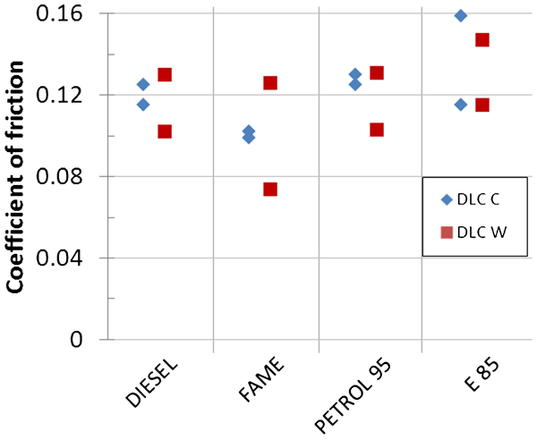
Steady state friction coefficients for the individual tests
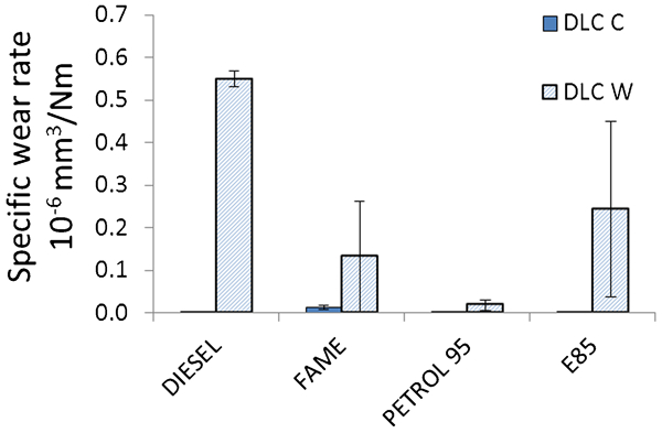
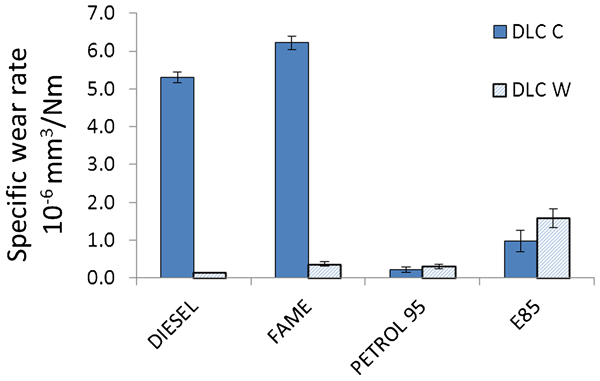
The wear rates of the coatings are presented in Fig. 3. The wear tracks on DLC W were much more scratched than the unworn coating with scratches of depth comparable to the top layer thickness. However, the material loss was relatively small. Mostly the material had become redistributed to form ridges along the scratches. DLC C showed almost no detectable wear and only a few scratches were seen in some of the wear tracks. The wear rates of the counter surfaces are presented in Fig. 4. The wear of the uncoated counter surfaces is clearly higher than that of the coatings. In diesel and FAME, the DLC C coating has worn the counter surface radically more than has the DLC W. In petrol and E 85 the difference was much lower, with slightly higher wear against DLC W.
Specific wear rates for the two coatings in the four fuels. Note that in several cases the wear rate was very close to zero
Specific wear rates for the uncoated counter surfaces worn against the two coatings in the four fuels
Analytical results
The SEM images of the wear scars on the balls run in FAME and diesel are displayed in Figs. 5 and 6. The wear scars produced in the contact against DLC C were much larger and had a smoother appearance, while the scars against DLC W were had deeper scratches. The EDS mapping of the ball from the test with the lowest friction coefficient after sliding in FAME against DLC W showed that tungsten and carbon has transferred from the coating to the counter surface, as exemplified in Fig. 7. Similar signals could be seen for the diesel test (not shown here). No sulphur or oxygen could be seen in the contact areas.
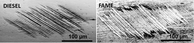
SEM images of the wear scars on steel balls run against DLC W in diesel (left) and FAME (right)
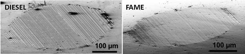
SEM images of the wear scars on steel balls run against DLC C in diesel (left) and FAME (right)
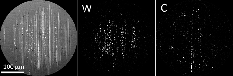
Appearance (SEM) and EDS maps showing the distribution of tungsten and carbon over the wear scar on a ball tested against DLC W in FAME
Raman analysis of the uncoated ball surfaces revealed mainly iron oxide on the ball that had slid against DLC C in FAME and diesel, while tungsten disulphide was identified after sliding against DLC W in the same fuels, see Fig. 8. Raman analysis of the balls that had been sliding in petrol and E 85 displayed no Raman active compounds.
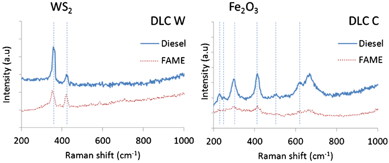
a) Raman spectra of a ball that has been sliding against DLC C. b) Raman spectra of a ball that has been sliding against DLC W. Peak positions corresponding to WS2 and Fe203 are marked8
XPS was performed on the balls tested against DLC W in FAME and diesel. Tungsten 4f peaks shows mainly oxides on the top surface, while after sputtering a few nanometres other compounds are seen as well, see Fig. 9a. When focusing on the energy intervals typical of tungsten and sulphur, with higher resolution than the overview spectra and longer acquisition times, sulphur with an energy position indicating sulphide was found, see Fig. 9b. Deconvolution of the signal after 11 min sputtering in Fig. 10 reveals metallic tungsten, tungsten oxide (possibly tungsten carbide) and a small signal from tungsten disulphide.
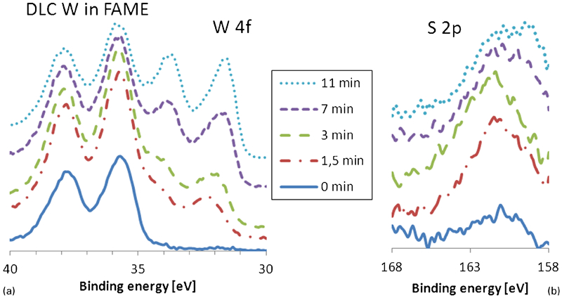
a) XPS spectra taken after different sputter times for the W4f peak, measured on a ball wear scar after sliding against DLC W in FAME. Mostly WO3 was found on the surface, and then other peaks appear deeper into the tribofilm. b) XPS sputter profile for the S 2p peak. The position corresponds to sulphide9
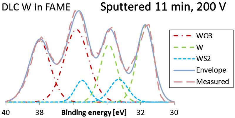
XPS spectra of s ball after sliding against DLC W in FAME. The surface was sputtered for 11 min at 200 V. Deconvolution of the W4f peaks clearly identified two sets of peaks. A third set was necessary to introduce to get sufficient fitting. Positions for the W4f7/2 for the sets were 35.8, 33.3 and 31.8 eV. The first set is addressed to WO3, the second to WS2 and the third to metallic W9
A TEM cross-section was prepared perpendicular to the sliding direction to get high resolution structural information and to see how the WS2 was distributed in the contact. The surface was covered by an approximately 5–30 nm thick tribofilm. The film showed occasional crystalline areas where most basal planes were close to parallell to the surface, as exemplified in Fig. 11. The planar distances were measured with the TEM software to be ∼6·2 Å, which is in good agreement with WS2 (d = 6·18 Å).10 The major part of the film was featureless and fast Fourier transforms displayed no crystallographic information, so the film was concluded to be amorphous. Using an energy filter, EFTEM elemental maps were aquired from the same area, as shown in Fig. 12. The maps confirmed that the crystalline area contained tungsten and sulphur. On top of the steel an iron oxide layer was found while the rest of the amorphous film mainly consisted of carbon plus some oxygen close to the interface with the iron oxide.
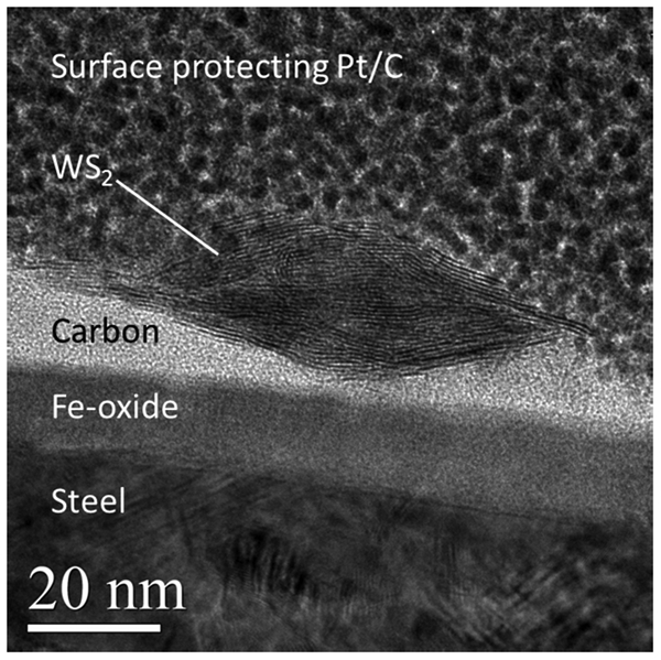
TEM micrograph of the tribofilm formed on the ball after sliding against DLC W in FAME showing small crystalline areas with a planar distance of ∼6.2 Å, identified as WS2. The cross section is prepared perpendicular to the sliding direction. The chemical information in the figure is based on the elemental maps shown in Fig. 12
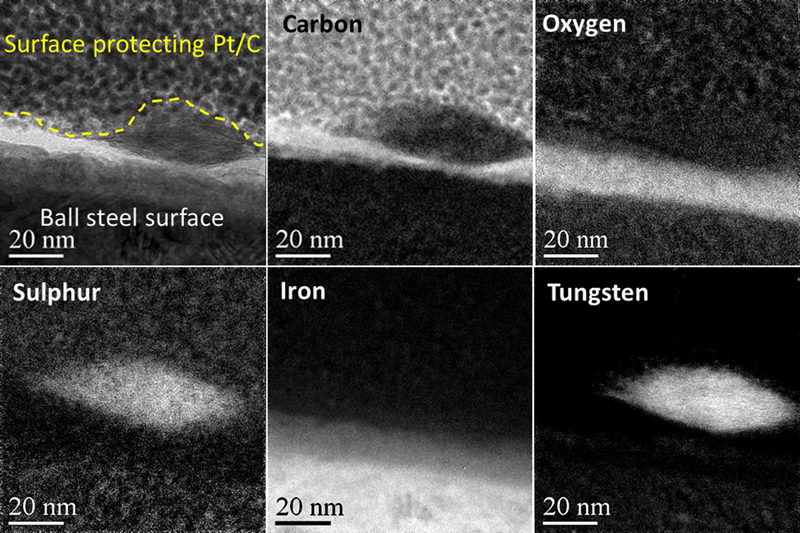
Energy filtered elemental maps of the area shown in Figure 11
Discussion
The most intriguing result of the present investigation is the formation of WS2 detected when testing the DLC W coating in Diesel and, most pronounced, in FAME. Formation and alignment of this well known low friction material has been reported for many other systems.5,6 However, here the supply of sulphur is very low compared to that in engine oils.
The FAME as well as the diesel contained <10 ppm of sulphur, according to the manufacturer, who also claims that the amounts are highly controlled. The FAME based on animal fats, may however contain significant quantities of sulphur, while the FAME tested, according to the manufacturer, was 100% rapeseed methyl ester (RME) containing only low amounts of sulphur.
Clearly, very small amounts of sulphur are sufficient to form the WS2 film, which is very thin and not fully covering. The coating contained no sulphur and the steel ball contains sulphur at similar levels stated for the fuels, but much less accessible than in the fluid. The authors therefore propose extraction of sulphur from the fuel as the most probable mechanism.
In diesel and FAME, the friction for the DLC W coating was reduced significantly in some of the tests, with a coefficient of friction as low as 0·074. Generally, the coating surfaces were scratched to a level that could influence the possibility to form a smooth and covering tribofilm. A significant difference in counter surface wear was seen between the two coatings, where the harder DLC C caused more than 10 times as much wear as the DLC W. The wear of the DLC C coating was negligible. The DLC W showed scratches of depth comparable to the top layer thickness. However, the material loss was relatively small. Mostly the material had become redistributed to form ridges along the scratches. As the hardness of the DLC W top coating is similar to that of the counter surface, it is not surprising that the top coating has been scratched. The coating design with the softer tungsten doped top layer may be beneficial by giving less counter surface wear and enabling formation of WS2 that drastically lowers the friction coefficient.
Raman analysis indicated that after sliding against DLC C, mainly Fe2O3 covered the ball, while for the low wear situations against the tungsten doped DLC W, the ball surfaces were mainly covered by a thin film of WS2, see Fig. 8. The fact that Fe2O3 was only found after sliding against DLC C, may indicate that either a tribochemical reaction takes place that increases the counter surface wear or that no protective transfer film is formed. The ball run against DLC W in FAME obviously contains a transfer film of tungsten and carbon, as seen in the EDS maps in Fig. 7. However, no sulphur or oxygen was observed with EDS, which could be due to the film being very thin and the accelerating voltage of 10 kV giving such a low surface sensitivity of EDS so that the weak signal drowns in the background noise.
The XPS analysis of the transfer film from DLC W in FAME confirmed that there was indeed both tungsten and sulphur transferred to the ball surface and also indications of tungsten disulphide, see Fig. 9. When sputtering WS2 there is always a risk of preferential sputtering of the sulphur,11,12 which will leave reduced tungsten, as can be seen in the spectra in Fig. 10. The chemical shift between metallic tungsten and tungsten carbide is however very small, so tungsten carbide cannot be ruled out. Investigations of the carbon 1s peak in the XPS spectra (not shown here) is then necessary. The peak maximum was positioned at 284·7 eV, indicating only non-bonded carbon. However, a broadening of the peak towards lower energies at higher depths indicates that small amounts of carbides may be present. Since there was an abundance of tungsten in comparison to sulphur in this system, there is most likely a mixture of metallic tungsten, transferred from the coating, and WS2, formed on the ball surface by tungsten from the coating and sulphur from the fuel. Possibly also small fractions of tungsten carbide may have been transferred.
In the TEM cross-section of a ball that run against DLC W in FAME, WS2 was identified in small areas with its basal planes aligned parallel to the surface; a well known low friction mechanism equivalent to the more known MoS2.13,14,15 A suggestion is that the formation of WS2 could be responsible for the large reduction in friction observed in some of the tests in FAME, and also help protecting the counter surface, either directly by the presence of WS2 on parts of the sliding surface or indirectly by ensuring that relatively more aggressive Fe2O3 is not formed to a higher degree.
WS2 was formed in the contact in streaks along the sliding direction rather than covering the whole scar, as seen in Fig. 7 and 11. It was estimated from the EDS maps that tungsten covers <3% of the area and carbon around 1%. This implies that WS2 rather than carbon is responsible for the reduction in friction. The amount of carbon may however be underestimated due to its low detection efficiency at 10 kV, while tungsten has its M peak at a level ideal for detection at 10 kV. Despite covering such a small area fraction, these streaks of WS2 seem to have a strong influence on the friction and counter surface wear, possibly due to that they are formed in the spots of highest contact stresses.
In petrol and E85, only small differences were found between the two coatings with respect to friction and counter surface wear. However, DLC W caused slightly higher wear in both fuels and the friction was more unstable within single tests. The coated surfaces were hardly worn with the exception of some scratches. These scratches were clearly deeper on the DLC W. Adding petrol or E85 to the contact, made the friction very unstable. This could be due to the high evaporation rate, affecting the amount of liquid being dragged with the contact. Alternatively, the variations are a sign of the formation and removal of an unstable sensitive tribofilm, in this system.
Conclusion
Adding a softer top coating containing tungsten to the DLC structure seems to enable the formation of WS2 in the contact when sliding in diesel, and most prominently in FAME, probably by extracting sulphur from the fuel and binding it to tungsten that transfers to the counter surface. Since this only occurs on small local areas of the contact (possibly due to the low sulphur content and the roughness of the contact), the effect on the friction is often minimal. However, in some tests involving sliding in FAME the friction has been significantly reduced, indicating a possibility to further optimise that system. The local presence of WS2 was shown to coincide with a dramatic reduction of the counter surface wear. The films were far from fully covering and very thin, making them problematic to identify. The films are believed to form in positions of high contact pressure, but this has not been clearly shown.
The DLC C coating containing a hydrogenated amorphous carbon top layer was more aggressive to the counter surface when sliding in diesel and FAME. Here, a layer of Fe2O3 was found on the steel ball surfaces. In these fuels, the DLC W clearly improved the tribological properties and limited the wear of the counter surfaces.
The DLC with a W doped top layer caused significantly less wear of the uncoated counter surface in two of the fuels. This result indicates the huge potential in developing DLC coatings with chemistries that promote formation of beneficial tribofilms and demote the formation of detrimental films, under the specific prevailing conditions.
The type of fuel had a strong influence on the wear rate of the steel parts that slid against the two DLC types.
It is once again clear that DLCs are not inert and that different coating chemistries should be evaluated when developing for different conditions.
Footnotes
Acknowledgements
The support from the Swedish Research Council grant no. 2009-15941-70482-35 and from the Swedish Foundation for Strategic Research via the program Technical advancement through controlled tribofilms is gratefully acknowledged. Thanks to André Hieke, Ionbond Netherlands, for providing the DLC coatings.
This paper is part of a special issue on Enabling and Emerging Lubrication Technologies