
Abstract
Present investigation deals with the wear behaviour of conventional cast Mg–5%Sn and Mg–5%Sn–2%Mm (Mm is misch metal) (wt.%) alloys studied through pin-on-disc wear experiments at four different loading conditions under ambient temperature. This study reports the effects of external applied load on the dry sliding wear rate and co-efficient of friction of both the alloys. It has been investigated that the volumetric wear loss increases with increasing applied load. It has also been found that the wear rate of Mg–5%Sn–2%Mm alloy is less than that of Mg–5%Sn alloy. The wear mechanism has also been studied through extensive scanning electron microscopy imaging. It has been investigated that wear occurs by delamination of flakes and ploughing (i.e., asperities).
Introduction
Magnesium alloys have the potential for high performance structural applications due to their excellent properties such as low density, high specific strength, superior damping capacity, etc., particularly in the automotive industry which leads to the weight reduction resulting in considerable economic advantages.1 In addition, these alloys also have good castability and machinability. Mg–Al based alloys such as AZ91 and AM60 are currently being used extensively in automotive components such as instrument panel, intake manifold and steering wheel to name a few.2 Once the alloys are chosen for application, degradation testing is essentially required under certain service environment. This occurs generally via corrosion, fatigue, wear, etc. However, these alloys are unsuitable for applications at temperatures above 120°C since they show poor creep resistance properties and large decrease in strength at elevated temperature due to thermal instability of their microstructure.3,4 Nowadays, wear is an important concern where magnesium alloys are generally subjected to different sliding motion in automotive/engine parts. The frictional heat generated due to repeated sliding motion, heating often influence tribological characteristics of those components. Depending on the temperature exposed, a series of dynamic behaviour such as adhesion, abrasion, oxidation, delamination, softening and even melting can take place and hence change in tribological parameters.
It has been investigated by many researchers that the variation in friction and the wear rate strongly depends on the applied load, geometry of specimens, relative surface motion, sliding velocity, surface roughness, alloy chemistry, system rigidity, temperature exposed, relative humidity, lubrication, vibration, etc. Among them, sliding velocity and the applied load are the two important factors which play significant role for the variation of friction and wear behaviour/mechanisms of materials under study.
In recent years, improving the elevated temperature properties has become a major challenge for possible applications of magnesium alloys in hot components (i.e., powertrain systems, etc.). Several approaches have also been accepted to improve the elevated temperature properties of these alloys.1,5,6,8 The most common way of improving the elevated temperature properties has been found to be the formation of thermally stable precipitates or dispersoids along the grain boundaries to resist the deformation by grain boundary sliding mechanisms.8 The most effective alloying elements used for such purpose are rare earth elements.9
Tin (Sn) has several characteristics suitable as an alloying element for elevated temperature applications, such as low diffusivity in magnesium (10×10−14 m s−2 at 400°C), low solid solubility in magnesium (0·035 at.% at room temperature) and high liquid solubility in molten magnesium (100% at 800°C). Moreover, primary Mg2Sn phase in Mg–Sn alloy system has a high melting temperature of about 770°C. These characteristics suggest that a fairly large volume fraction of thermally stable Mg2Sn particles can be formed during solidification. Recently, Kang et al.7 reported the high temperature creep properties of Mg–Sn alloys in their pioneer studies. There are limited studies available on tribological properties of Mg–Sn alloys in the published domain.
More importantly, the frictional heating generated during sliding motion which leads to changes in the wear mechanism is poorly understood from the published literatures. In spite of the above investigations/discussions, the effects of sliding speed and the applied normal load on wear behaviour of present magnesium alloy under study are yet to be clearly understood. In this paper, we have investigated experimentally the effect of rare earth (misch metal) on the microstructural features/morphologies and the tribological characteristics of Mg–5%Sn alloy at different loading conditions under ambient temperature. The knowledge of tribological properties is an important parameter for design of an alloy for any applications.
Experiments
Two alloys with the nominal compositions of Mg–5%Sn and Mg–5%Sn–2%Misch metal (wt.%) have been prepared by melting of magnesium and tin in a mild steel crucible coated with boron nitride under the protection of covering flux (20%KCl, 50%MgCl2, 15%MgO, 15%CaF2) and the high purity Ar (99·99%) gas. Misch metal (Mm) contains 55%Ce, 25%La, 15%Nd, 3%Pr and rest other alloying elements. For preparing Mg–5%Sn–2%Mm alloy, freshly cleaned Mm has been added after melting magnesium and tin and then the temperature of the melt was raised to ∼770°C. The melt was stirred to assist the dissolution of the alloy to obtain good chemical homogeneity. It was then held at 750°C for ∼30 min, and finally cast in a 15 mm diameter steel mould. The microstructures of the samples were examined under optical microscope. Picric acid based etchant (6 g picric acid, 5 mL acetic acid, 100 mL ethanol and 10 mL H2O) was utilised to etch the polished specimens. The sliding wear tests were carried out using a pin-on-disc machine. The pins of 4 mm diameter and 60 mm length were fabricated from 15 mm diameter rods (solid cylindrical pins) and made to slide against a low alloy steel disc (material: 103Cri-Eng-31HRS60W61, equivalent to AISI 4340) of diameter 215 mm and hardness of 62Rc. The track radius and disc speed were maintained at 67 mm and 100 rev. min−1 respectively to maintain a constant sliding velocity of 0·70 m s−1. The contact surfaces of the pins and disc were polished to a roughness of Ra = 0·1 μm before each wear testing. Four loads, namely, 9·8, 19·6, 29·4 and 39·2 N were applied for each sample in the present work. Each wear tests were repeated three times to achieve the representative results. Tangential force and co-efficient of friction were measured continuously with an electronic sensor attached to the machine. A frictional force (N) and pin length reduction (μm) were measured from the sensors output data as a function of time. The specific wear rates of the alloy specimens, define as the cumulative wear loss (CWL) per unit sliding distance per unit load, were calculated. The wear test was carried out for 30 min (total sliding distance of ∼1·263 km) through room temperature and the relative humidity of 50–55%. Surface roughness of the worn surfaces of these alloys has been measured by roughness tester (Taylor Hobson Precision – Form Talysurf Series 2). The surfaces of the worn samples, as well as the wear debris, were cleaned by acetone and examined under the scanning electron microscope (SEM) through secondary imaging. The Vicker's hardness of the wearing surface of each pin was measured and recorded under 1 kg load after completion of each wear test.
Results
The densities of the alloys are measured by Archemedies’ principle and found to be 2015 kg m−3 for Mg–5%Sn and 2116 kg m−3 for Mg–5%Sn–2%Mm alloys. These values are close to their theoretical values (2018·5 kg m−3 for Mg–5%Sn and 2119 kg m−3 for Mg–5%Sn–2%Mm alloys) which indicate that the samples are almost free from porosity. The microstructures of these alloys have been shown in Fig. 1. These figures depict the primary α-Mg phase (bright/white) region and eutectic (α-Mg+Mg2Sn) phase (dark) region. In addition, Fig. 1b contains intermetallic phases pertaining to rare earth elements. It was found that Mg–5%Sn–2%Mm (Fig. 1b) alloy is having finer grain size compared to Mg–5%Sn alloy (Fig. 1a). The hardness value of Mg–5%Sn–2%Mm (46 HV) is significantly higher than Mg–5%Sn (38 HV) alloy in the as cast condition. The XRD patterns of both the alloys are represented in Fig. 2. The XRD results indicate that Mg–5%Sn alloy comprises of α-Mg and Mg2Sn phases and additionally Mg12Ce phase is present in Mm containing alloy.
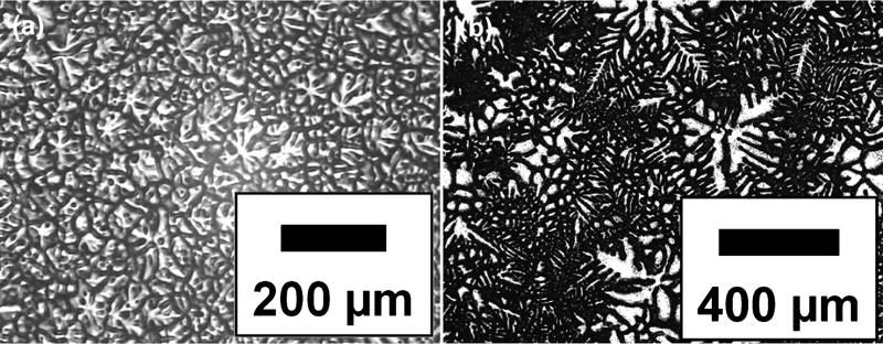
Optical micrographs of a Mg–5%Sn and b Mg–5%Sn–2%Mm alloys showing primary α-Mg phase (bright/white) and eutectic (dark)
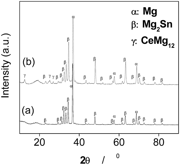
X-ray diffraction patterns of a Mg–5%Sn and b Mg–5%Sn–2%Mm alloys
Figure 3 represents the cumulative wear loss (CWL) in micrometers (μm) as a function of sliding distance in meters (m), at 9·8 and 39·2 N loads respectively. Cumulative wear loss against distance travelled of as cast Mg–5%Sn alloy at 49 N loads is shown in Fig. 4. The average volumetric wear rate (WR) counted from the beginning of the test to any particular stage is expressed as: WR = volumetric wear loss (mm3)/[total distance travelled in meters (m)×load applied in Newton (N)]. The average wear resistance (WRe) is defined as the inverse of the average wear rate and is expressed as: WRe = m.N/mm3. The cumulative volumetric wear loss, specific wear rates against wear load are presented in Figs. 5 and 6 respectively. Figure 7 shows the variation of friction co-efficient (μ) with sliding distance for both the alloys. Figure 8 depicts average friction co-efficient (μ) with the applied load. The co-efficient of friction of Mg–5%Sn alloy initially increases and then almost constant with increasing loads whereas at low loads, co-efficient (μ) of Mg–5%Sn–2%Mm alloy is higher than that of Mg–5%Sn alloy.
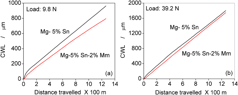
Cumulative wear loss against distance travelled of as cast Mg–5%Sn and Mg–5%Sn–2%Mm alloys at different loads of a 9·8 N and b 39·2 N, sliding speed 0·7 ms−1
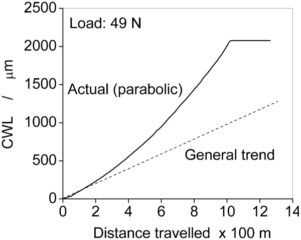
Cumulative wear loss against distance travelled of as cast Mg–5%Sn alloy at 49 N load showing seizure of pin sample
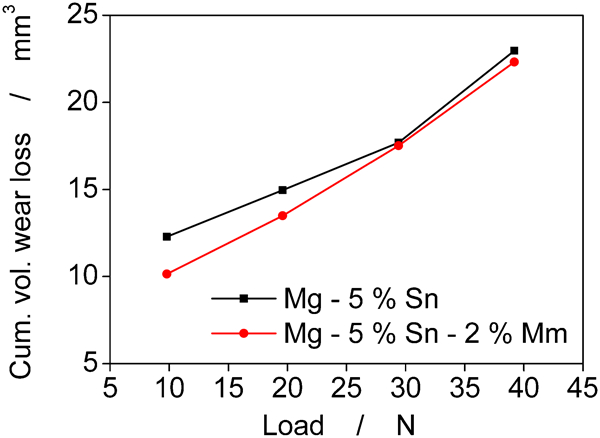
Cumulative volumetric wear loss against loads of as cast Mg–5%Sn and Mg–5%Sn–2%Mm alloys
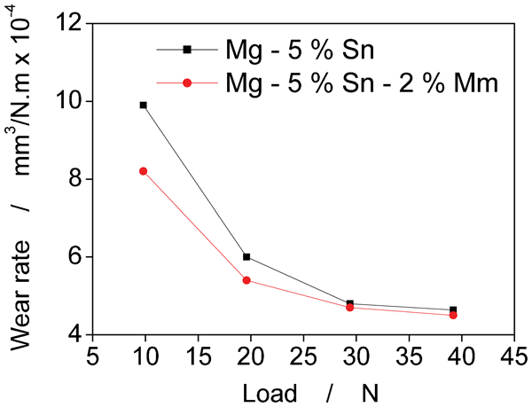
Specific wear rate against loads of as cast Mg–5%Sn and Mg–5%Sn–2%Mm alloys
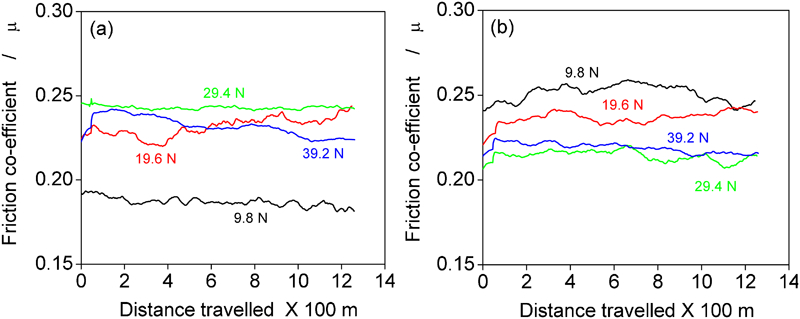
Variation of co-efficient of friction against distance travelled at 9·8, 19·6, 29·4 and 39·2 N loads for as cast a Mg–5%Sn and b Mg–5%Sn–2%Mm alloys
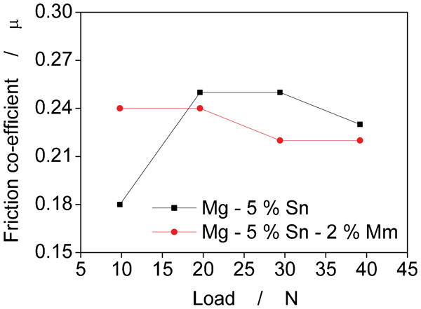
Variation of friction co-efficient against at 9·8, 19·6, 29·4 and 39·2 N loads for as cast Mg–5%Sn and Mg–5%Sn–2%Mm alloys
The hardness (VPN) of the worn surfaces of the alloys measured and depicted in Fig. 9. This indicates that the hardness of the pin samples increased with increasing loads for both the alloys. Figure 10 shows variation in worn surface roughness under the four different loading conditions. It has been observed that the roughness values are increasing as load is increasing for both the alloys. The SEM images of the worn surfaces of the pin samples of Mg–5%Sn alloy are presented in Fig. 11. It is evident from Fig. 11b that Mg–5%Sn alloy has undergone plastic flow and cracking. This alloy also shows distinct grooves, suggesting ploughing of the pin surface. These worn surfaces are the areas from which the wear debris had been removed. The SEM images of the worn surfaces of Mg–5%Sn–2%Mm alloy are given in Fig. 12 indicating plastic flow of the matrix crack nucleation, propagation and crevice formation of the alloy. The delamination wear was observed in Mg–5%Sn alloy tested under 49 N load and that is evident in Fig. 13. The morphology of the wear debris collected from both the samples is shown in Fig. 14. The Mg–5%Sn–2%Mm alloy may undergo oxidation during the wear test. The existence of the probable oxide layer is shown in Fig. 14 (marked as ‘A’). Correlation between experimental and theoretical values of wear loss of as cast Mg–5%Sn and Mg–5%Sn–2%Mm alloys are shown in Fig. 15.
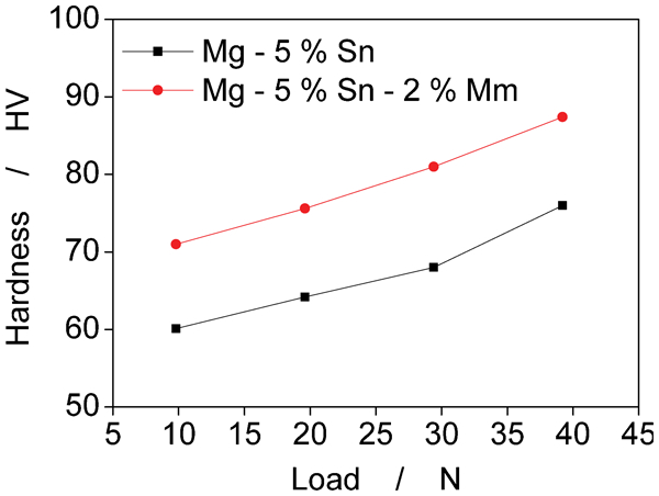
Variation of hardness of worn surfaces of Mg–5%Sn and Mg–5%Sn–2%Mm alloys at 9·8, 19·6, 29·4 and 39·2 N loads
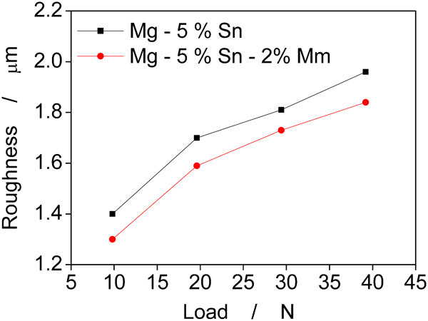
Variation of worn surface roughness against 9·8, 19·6, 29·4 and 39·2 N loads for as cast Mg–5%Sn and Mg–5%Sn–2%Mm alloys
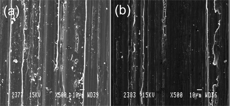
Images (SEM) of worn surfaces of as cast Mg–5%Sn alloy at a 9·8 N and b 39·2 N loads, sliding speed 0·7 ms−1
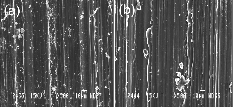
Images (SEM) of worn surfaces of as cast Mg–5%Sn–2%Mm alloy at a 9·8 N and b 39·2 N loads, sliding speed 0·7 ms−1
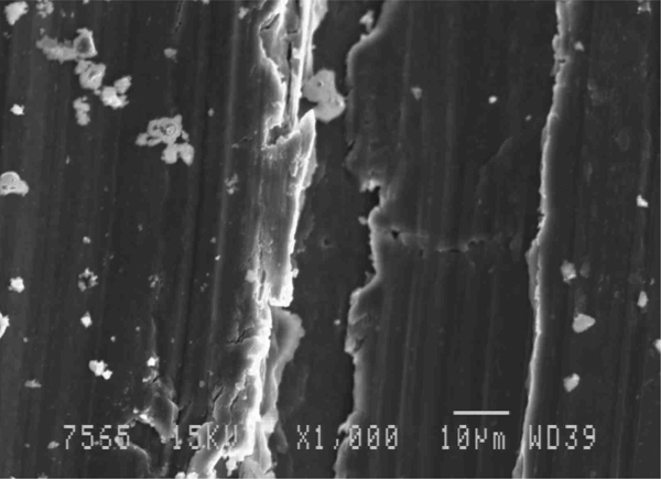
Images (SEM) of worn surfaces of as cast Mg–5%Sn alloy, sliding speed 0·7 ms−1, applied load 49 N
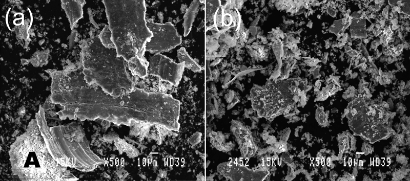
Views (SEM) of wear debris of as cast Mg–5%Sn–2%Mm alloy at a 9·8 N and b 39·2 N loads, sliding speed 0·7 ms−1
Discussion
From the wear tests of Mg–Sn alloys, the following aspects of wear have been assessed:
over all wear resistance,
effect of misch metal on the wear characteristics, and
wear mechanism.
During wear run the volumetric wear loss suffered by the pin materials, after a short transit period, increased linearly with increasing sliding distance, indicating a steady state wear behaviour.
The wear loss in the case of Mg–5%Sn alloy is distinctly higher than that of Mg–5%Sn–2%Mm at all loading conditions. In fact, wear testing could not be conducted on Mg–5%Sn alloy pin sample at 49·0 N load (highest load in the present work) due to the occurrence of seizures and high rate of wear. It suffered a wear loss of above 2 mm in travelling around 1 km distance (Fig. 4). The sudden change in the wear rate for the above alloy indicates the clear variation in wear mechanism from mild to severe. This can be explained by the mechanism proposed by Lim and Ashby.10 When the pin surfaces are placed in contact with the disc, the real area of pin contact is usually very small. The large local pressure at the points of real contact (the asperity contacts) can forge soft metallic junctions between the surfaces even under static conditions. Under excessive load, the real area of contact grows until it is equal to the nominal area of the pin surfaces and the surface seizes completely. The difference in cumulative wear loss between both the alloys are decreasing as load is increasing (Fig. 3). The reason behind this phenomenon is attributed to the work hardening which takes place in the pin samples during the subsequent wear run. The severity of work hardening rate in case of Mg–5%Sn alloy is lower as compared to Mg–5%Sn–2%Mm alloy. This is due to the fact that in the case of alloy containing Mm, the grain size becomes finer leading to more grain boundary area causing more numbers of dislocation generated during deformation. The probable mechanisms for dislocation formation include the presence of grain boundary initiation, precipitates and dispersed phases. The presence of intermetallic phases in Mg–5%Sn–2%Mm alloy is prone to initiate more numbers of dislocations as compared to Mg–5%Sn alloy. These generated dislocations further causes locking of dislocations during plastic deformation and that leads to work hardening of the alloy.11
The volumetric wear loss is more at higher loads due to the high wear rate at higher loads. The specific wear rate of Mg–5%Sn–2%Mm alloy is significantly lower at lower load which is attributed to the combined effect of low porosity and finer grain size as compared to Mg–5%Sn alloy. The high wear rate (Fig. 6) at the initial stage is due to the adhesive nature of the wear which is associated with high material loss and high value of co-efficient of friction (μ). There are two factors that determine the magnitude of the frictional force (N), and hence the co-efficient of friction (μ). These are the mechanical interaction of the surface asperities of the two contacting bodies, and the formation of adhesive junctions at the areas of the contact between the asperities. The co-efficient of friction against distance travelled of both the alloys are shown in Fig. 7. For Mg–5%Sn alloy, the friction co-efficient is increasing with increasing applied load but for Mg–5%Sn–2%Mm alloys, it shows the reverse trends. The average value of co-efficient of friction (μ) at different loads is shown in Fig. 8.
The pieces of delaminated wear debris are already so severely work hardened and fractured that they do not stick to the sliding surfaces and torn away. The higher co-efficient of friction in Mg–5%Sn alloy is due to the soft nature of the alloy as compared to the harder Mg–5%Sn–2%Mm alloy. The increase in co-efficient of friction with increasing load from 9·8 to 19·6 N in the case of Mg–5%Sn alloy indicates adhesion of the pin to the sliding surface during the wear run, with the increasing load. The localised heating (due to sliding) actually facilitates sticking of the pin to the disc surface. An increase in friction co-efficient at elevated temperature has also been reported for particle reinforced cast alloy composites elsewhere.12 The rise in friction co-efficient with increase in wear load may be attributed to enhanced accumulation of wear debris at the pin and disc surfaces. The increased hardness of the worn surfaces of the pin materials with increasing load is due to the work hardening of the materials. Therefore, the extent of work hardening is more with increase in load. The material transfer mechanism has been related to the surface roughness of the pin specimens. The increase in surface roughness with increasing load is due to the plastic deformation of the worn surfaces.12 Surfaces roughness of Mg–5%Sn–2%Mm is lower than that of the Mg–5%Sn alloys as wear rate is (Fig. 10).
The SEM images (i.e., secondary images) of the worn surfaces of the samples have depicted some interesting features to understand the wear mechanism. The worn surfaces of the pin materials show diverse topographical features/morphologies. Most of the worn surfaces consist of smooth strips, the surfaces of which are characterised by fine scoring marks. These smooth strips were extend uninterrupted from one end of the pin specimen to the other. The worn surfaces of the Mg–5%Sn–2%Mm alloy are heavily scored than Mg–5%Sn alloy. Scoring may be due to abrasion by entrapped debris, work hardened deposits on the counter face.13–15 The wear by scoring mechanism, however, may not lead to a large volume of wear since the amount of material removed from a fine groove is small. The worn surfaces of Mg–5%Sn alloy at 9·8 N load (Fig. 11a) shows extensive and long continuous grooves on the surfaces parallel to the sliding direction whereas the same alloy at 39·2 N load (Fig. 11b) shows much lesser grooves. The width of the continuous grooves in Mg–5%Sn alloys is larger than that of the grooves on Mg–5%Sn–2%Mm alloy. As the load increases, the width of the grooves increases significantly. Irregular plastic flow lines (Fig. 12b) indicates the occurrence of extensive plastic deformation during wear run. Cracks and strips of roughened surfaces are also seen (Fig. 12b). The cracks propagate in the sliding direction. Crack nucleation, generally, occurs at some depth below the surface, owing to high hydrostatic compressive pressure acting near the asperity contact which has been discussed elsewhere.16 Crack may initiate in the highly work hardening layer, particularly in the subsurface region. When cracks grow and get interconnected, a layer of material is removed leaving a crater. At the highest load (49 N), the mixed modes of wear, i.e. ploughing with local delamination on wear have been observed (Fig. 13).
During wear run, the worn surface particle debris agglomerated and stick to the grooved areas. This is very prominent in the case of Mg–5%Sn–2%Mm alloy (Fig. 12a). The interface temperature increases as the wearing couples slides against each other that facilitate sticking of the wear debris at the grooved surfaces, which has been described elsewhere.17 Wear particles are generated when a subsurface crack breaks through the surface. Since the propagating end of the crack (i.e., the crack tip at which the stress is maximum) is always located behind the moving asperity, the crack reaches the surface after the asperity moves over the crack. Consequently, the wear particles always lift up from the surface so that the underside is facing the direction opposite to the slider motion. This direction is opposite to that of similar flat particles formed by the deformed asperities and thus, enables an easy separation of particles formed by subsurface crack propagation from those formed by deformed asperities. The delaminated wear debris particles are already so severely work hardened and fractured that they do not stick to the sliding surface any further and are removed entirely. The SEM image of Fig. 14a confirms this fact. The wear debris of Mg–5%Sn–2%Mm alloy appears to be oxidised in all the loading conditions (Fig. 14). These figures also show that a layer of material has been removed as debris from these surfaces by means of delamination wear mechanism. The debris is in the form of thin sheets (shown in Fig. 14a). According to the mechanism of delamination,18 once a crack is present, further loading and deformation may cause the crack to extend and propagate, resulting in the delamination of a thin sheet. The fracture surfaces are largely composed of numerous voids and cracks, and their growth and ultimately their interlinkage form wear debris in the form of large flaky piece. Figure 11a shows the propagation of a crack in the smoother region of the worn surfaces of the Mg–5%Sn alloy. For Mg–5%Sn–2%Mm alloy, the subsurface cracks are shorter in length but quite thick, which indicate a very low wear rate for these alloys to crack propagation.


Results of fitting data for the conventional cast Mg-5%Sn and Mg-5%Sn-2%Mm alloys
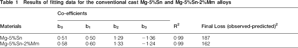
The correlation R for the fitting is reasonably good (0·9980). The values of wear loss predicted using equation (2) are compared with experimental data for both Mg–5%Sn and Mg–5%Sn–2%Mm alloys as shown in Figs. 15a and b respectively. The graphs indicate a good general agreement between the predicted and the experimental data with an error range of ± 6%. The experimental data obtained can be fitted to an exponential equation W = 0·51L0·5P1·29H −1·36 for Mg–5%Sn alloy and W = 0·58L0·6P1·33H−1·24 for Mg–5%Sn–2%Mm alloy with good correlation and high coefficient of determination. As expected, the exponent of hardness is negative. All the exponents deviate from unity may be due to the ignorance of the initial microstructure. The variation of load and hardness exponents clearly indicates that the initial microstructure plays an important role to the wear behaviour.
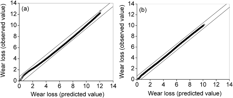
Correlation between experimental and theoretical values of wear loss of conventional cast a Mg–5%Sn and b Mg–5%Sn–2%Mm alloys
Conclusion
The Mg–Sn alloys investigated exhibit plastic deformation and work hardening during wear testing, the Mg–5%Sn–2%Mm alloy work hardened to a greater extent than Mg–5%Sn alloy. The following are summarised from the present experimental evidences:
Wear occurs by plastic deformation and cracking of the matrix followed by delamination of flakes and also by ploughing. In addition, detached hard dispersoid particles also contribute to wear.
Co-efficient of friction rises sharply at high wear load for Mg–5%Sn alloy and the same remains constant for Mg–5%Sn–2%Mm alloy with increasing load.
Specific wear rate decreases with increasing load for both the alloys.
Hardness of the worn surfaces of the pin materials increases with increasing load and sliding distance.
Surface roughness of both the alloys is increasing with increasing wear load.
Footnotes
Acknowledgements
The authors wish to record their grateful thanks to the Director, CSIR-National Metallurgical Laboratory for permission to publish this paper and also to Dr D. Mondal for fruitful discussion. The authors are grateful for the constructive comments by the respected reviewers.