
Abstract
The objective of this study is to investigate the enhancement of tool life and wear resistance with a physical vapour deposition (PVD) process applied using aluminium chromium nitride (AlCrN) and titanium nitride (TiN) coating on carbide inserts. Flank wear experiments are carried out on a computer numerically controlled (CNC) machine under wet conditions with both the coated inserts. Effectiveness of the coating on the tool life and its resistance to flank wear are observed at various cutting parameters such as cutting speed and feed rate by following the principle of design of experiments (DOE). It is inferred that AlCrN coated carbide tools perform nearly 70% better than the TiN coated carbide tools under high cutting speed and feed rate. AlCrN coating also enhances the durability of tool for metal cutting and thereby improves tool life even under harsh cutting conditions. A response surface methodology (RSM) is utilised to arrive at the optimum value for the various parameters which are responsible for improving the wear resistance and tool life.
Introduction
Tool life plays a critical role in an estimation of the productivity level expected for specific cutting conditions in manufacturing. It becomes extremely important both economically and for good quality that a tool insert should be chosen in such a way that it wears out in a progressive manner rather than being unpredictable for its working life due to its uncertain machining capability. Wear resistant coating on cutting tools is the most significant development in cutting tool technology.1 There are two basic regions of wear in a cutting tool, which are flank and crater wear. Flank wear is generally attributed to rubbing of tool along the machined surface, thus causing adhesive and/or abrasive wear. It is also due to the prevalence of high temperatures during a machining process thereby affecting tool material properties as well as the workpiece surface. Crater wear occurs on the rake face of the tool and changes the chip/tool interface geometry as well as affecting the cutting process. The most significant factors influencing crater wear are temperature at the tool/chip interface and the chemical affinity between the tool and the work piece materials. The effect of tool wear includes increase in cutting forces; increase in cutting temperature, poor surface finish and decrease in accuracy of finished parts. However, the selection of tool should meet the criteria such as higher hardness, higher strength and longer survivals.2 It may not always be feasible owing to the following reasons:
it is not cost effective in many situations
the concerned component is so complicated in shape and design that technically it is not feasible to change the material.
To enhance the tool performance, tool inserts are provided with a surface coating. Surface coating on carbide cutting tools is to enhance the properties such as high wear resistance, lower heat generation, thermal loads, corrosion and lower cutting forces, thus enabling them to perform better at higher cutting conditions than their uncoated counterparts. Lim and Lim3 suggested that coated inserts could be employed in a more cost effective manner when the machining conditions are determined based on the wear. Coated tool inserts offer much improved resistance to wear during machining, resulting in an increase in tool life rather than uncoated ones. The mechanical properties of tool and their corresponding cutting parameters are studied4–10 for enhancement of tool life and wear resistance. PalDey and Deevi11 have reviewed available literature for single layer and multilayer wear resistant coatings of titanium nitrate and aluminium nitrate coatings extensively. Particularly, studies12–18 are carried out on titanium and aluminium based cutting tools. These coated materials not only help reducing the wear and increasing the tool life but also improve strength and chemical inertness, reduce friction, and make the parts more stable at high temperatures.19–21 The researchers studied that the surface coating materials such as TiCN, TiAlN, AlTiN,22 TiAlN/CrN and TiAlCrN23 on tool performance. It is inferred that coating material on tool improves the tool life and wear etc. Further, the researchers24–30 studied the effect of cutting parameters on tool life, wear rate, roughness and machining forces etc using RSM in dry turning conditions.
In the present study, focus is on comparison of TiN and AlCrN coated tool inserts in high speed CNC machining under wet conditions. Most of the important parameters like cutting speed and feed rate on tool life and wear are studied and their significance on tool coating was analyzed using RSM.
Experimental
Workpiece material
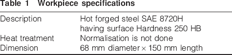
Turning experiments are performed using a CNC machine under wet conditions. The following cutting parameters are used: cutting speed of 300–500 m min−1 and feedrates of 0·1–0·3 mm rev−1. Flank tool wear evaluation is conducted on the coated tool inserts by video graphic technique. The workpiece material is SAE 8720 H steel and its specifications are listed in Table 1. The workpiece material is selected as ISO 95MnCrW1 with hardness 23 HRC.
Workpiece specifications
Cutting inserts and tool holder geometry
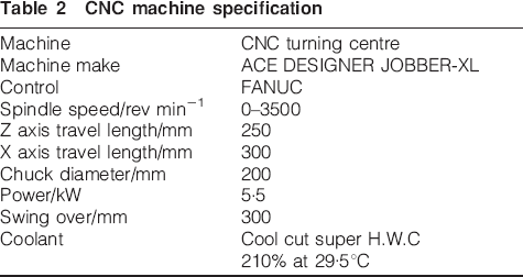
Carbide inserts are used in the turning tests done on the CNC machine under wet conditions. The cutting inserts has ISO designation of DNMG 150608 with M5 geometry. The cutting tool geometry is 0·8 mm of nose radius, 55° angle of cutting edge and 0° of back clearance angle. Two types of cutting insert such as TiN and AlCrN are used in the experiment. The inserts are mounted rigidly on a tool holder with ISO designation of PDJNR. The machine specifications are listed in Table 2. The water based emulsion derived from Coolcut Super H.W.C. 210% at 29·5°C is used as a cutting fluid.
CNC machine specification
Work material
The cutting performance tests were performed on SAE 8720 H low carbon steel based on AISI-SAE standard carbon steel. The work piece was hot forged but normalisation is not done and is shown in Fig. 1. Figure 1 shows both the forged raw workpiece as well as the machined piece.
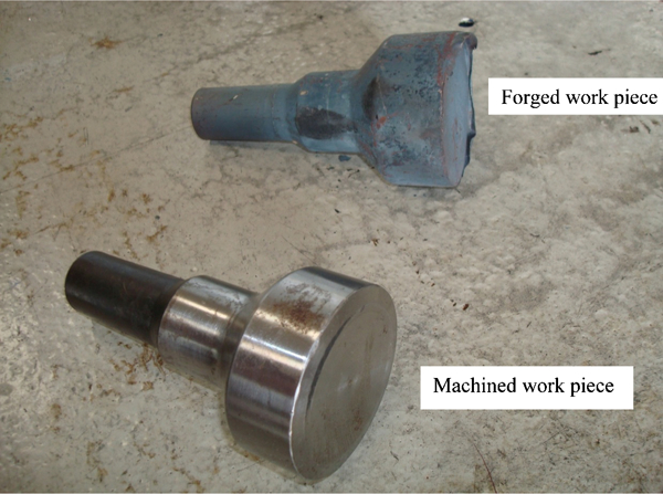
Forged and machined workpieces
Optimisation process
Central composite design (CCD) matrix modelling of design is very economical for extracting the maximum amount of information with minimum number of experimental runs. The central composite design matrix requires a number of experimental runs evaluated using the equation


Variables and experimental levels*
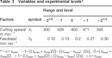
*−α = xmin, −1 = [(xmax+xmin)/2]−[(xmax−xmin) /2α], 0 = (xmax+xmin)/2, +1 = [(xmax+xmin)/2]+[(xmax−xmin) /2α], +α = xmax
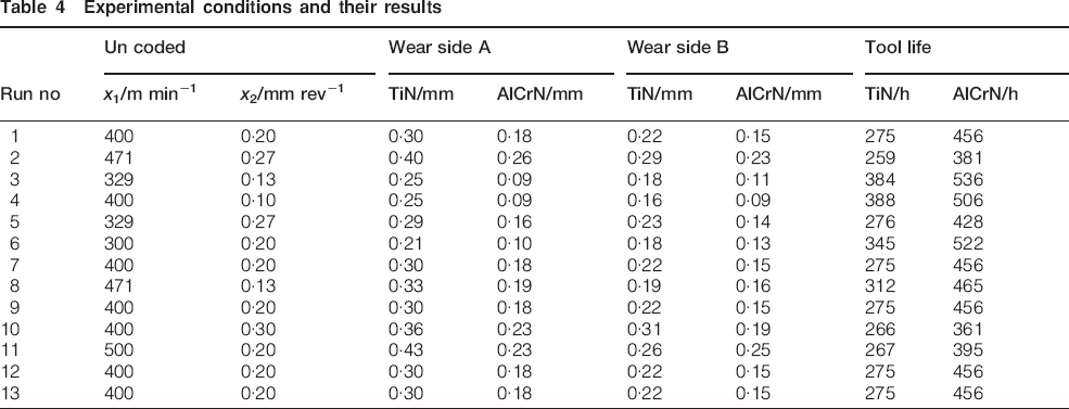
Experimental conditions and their results
Results and discussion
Wear measurement
Flank wear is measured using the videographic measuring system at two sides (A and B) of the inserts (Fig. 2). Image of the tool is captured using a video camera before the cutting operation. When the tool failed, again the flank surface is video graphed. Both the images are compared using an image processing software and thereby arrive at a thickness of material lost in the flank surface. Figure 2b shows the wear morphology on flank face for a TiN coated tool insert when employed with the cutting speed of 450 m min−1, a feedrate of 0·25mm rev−1. At this turning condition, the longest tool life of 431 numbers of components was achieved. As shown in the progressive wear picture, the TiN coating has been removed from the cutting edge, and the thermal crack is already been observed on the cutting edge of the flank face. Figure 2d shows the wear morphology on flank face for an AlCrN coated tool insert when employed with a cutting speed of 450 m min−1, a feedrate of 0·25mm rev−1. At this turning condition, the longest tool life of 609 numbers of components was achieved. As shown in the progressive wear picture, the AlCrN coating has been removed from the cutting edge, and the thermal crack is already been observed on the cutting edge of the flank face.
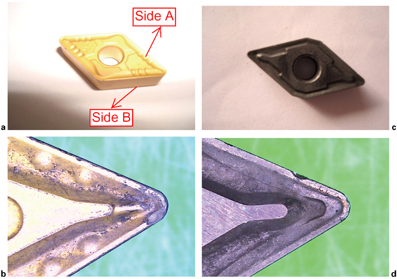
TiN and AlCrN coated tool inserts before and after machining operation:
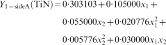
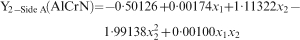
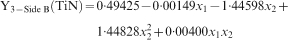
As the preliminary studies shows that AlCrN coated tool carbide wears less than the TiN coated tool carbide. Moreover, these parameters are systematically studied by using DOE concepts. The regression equation obtained for TiN coated tool wear of side A that relates the operating variables for data of Table 4 is given by equation (3)
Statistical t and p values for TiN coated insert side A (R2 = 0·985)
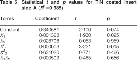
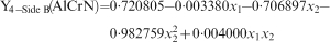
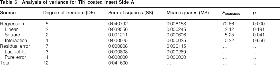
From Table 6, it is observed that the calculated p value is <0·05. This indicates that the model is statistically significant. The F value of Table 6 indicates that equation (3) is statistically significant. This further indicates that equation (3) can be effectively used to predict tool life in various operating conditions. Estimated values and match with experimental data points, indicating a good fitness (R2 value of 0·97 for TiN coated inserts of Side A). A p value less than 0·005 indicate that the model is statistically significant. Similarly, statistical analysis carried out for AlCrN coated tool for Side A, TiN and AlCrN coated tool for Side B. The statistical analysis results are given in Tables 7–12 in Appendix 1. The regression equations are given as equations (4)–(6).
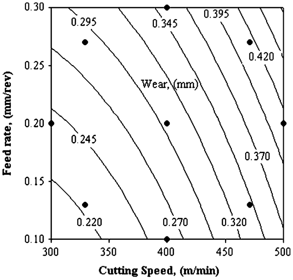
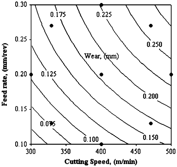
Effect of cutting parameters on wear for TiN coated on Side A
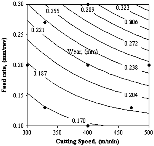
Effect of cutting parameters on wear for AlCrN coated on Side A
Analysis of variance for TiN coated insert Side A
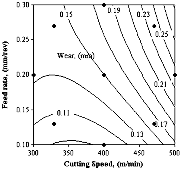
TiN flank wear rate is more than AlCrN, it indicates wear performance hindering due to AlCrN coating on carbide tool. AlCrN coating performs much better than TiN coatings for tool inserts. This flank wear increased at high cutting speed due to a contact area at the chip/ tool interface and caused concentration of high temperature very close to the cutting edge. Khrais and Lin35 reported that Arcona is showing better performance than the other coatings such as TiN, TiAlN, TiCN and AlTiN. It is concluded that AlCrN coated carbide tool performs approximately 70% for Side A and 23% for Side B better than TiN coated carbide tools under the high cutting speed and feedrate as well as enhance the tool life. Similar inferences are observed for B side of TiN and AlCrN and thus the results are presented in Figs. 5 and 6. In addition, Fig. 7 shows that the comparison of uncoated and coated inserts of TiN and AlCrN. It also shows that coating improves the flank wear resistance of inserts.
Effect of cutting parameters on wear for TiN coated on Side B
Effect of cutting parameters on wear for AlCrN coated on Side B
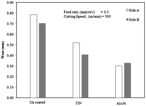
Comparison of uncoated and coated inserts
Enhancement of tool life
Effect of cutting parameters on tool life of TiN and AlCrN coated inserts
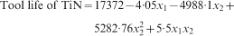
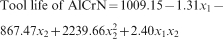
Statistical analyses are performed and results are given in Tables 13–16 in Appendix 2 for the regression equations obtained for tool life of TiN and AlCrN that relates the operating variables is given by Equations (7) and %(8).
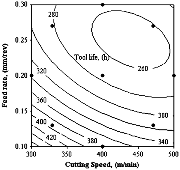
Effect of cutting parameters on tool life for TiN coated
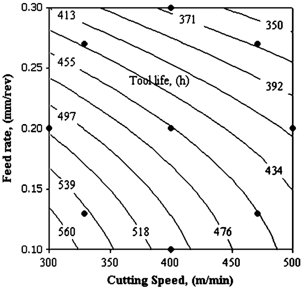
Effect of cutting parameters on tool life for AlCrN coated
Conclusion
In the present work, the tool performance has been evaluated in terms of tool life and flank wear as a function of cutting parameters such as cutting speed and feed rate. The flank wear resistance and tool life are studied on TiN and AlCrN coated tool inserts in computer numerically controlled machine under wet condition. It is concluded that AlCrN coated on carbide tool performs better than TiN coated on carbide tool under high cutting speed and feedrate. AlCrN coated tool inserts provide more resistance to wear during machining, leading to an increase in tool life.