
Abstract
Multifunctional coatings, widely used in tribological applications, have their properties strongly influenced by the interaction of the system coating/substrate. The use of multilayered coatings has been pointed out as a solution for the problem of high internal stresses that can be generated in coated systems, in particular in the case of soft substrates. In multilayered coatings, a decrease in the stress gradient between substrate and coating improves adhesion. Moreover, the thickness of the coating has shown a strong influence on the tribological behaviour of the coated system. This paper, through widely used and efficient techniques, seeks to assess the influence of the thickness of different layers (DLC and CrN) on the response of a multifunctional coating. Si rich DLC and CrN coatings with different thicknesses were deposited on a steel substrate (AISI 1020) by Plasma Enhanced Magnetron Sputtering (PECVD). Scanning electron microscopy (SEM) and Raman spectroscopy (RS) were used in order to characterize the chemical composition and microstructure of the coatings. Instrumented indentation and scratch test techniques were used to measure hardness, elastic modulus, and adhesion of each layer. Critical loads were determined by visual analysis, using SEM in conjunction with the curves obtained in the scratch tests. The evaluation of the effect of the thicknesses of the layers allowed an optimised design of the multifunctional coated systems with improved durability.
Keywords
Introduction
Solid lubricant coatings have received a great attention from the academic and industrial community in the past years. Despite this, no solid lubricant can provide low friction and low wear under varying conditions of temperature and environment.1 On the other hand, if the solid lubricant is hard, serious adhesion problems can arise due to high internal stresses generated in the coated system if the substrate is soft. In order to achieve a combination of high wear resistance, load support and low friction coefficient, multi-functional coatings can purposefully combine multi layers.2,3 Moreover, multilayered coatings generally have less severe stress distributions than monolayers having the same total thickness and the same top layer/substrate modulus ratio.4
Mechanical, thermal, electrical, optical and other properties of a particular coating are strongly influenced by the coating/substrate interaction, which can limit the potential for technological application of this coating. Moreover, the thickness of each layer has shown a strong influence on the tribological response of multifunctional coatings, as predicted by numerical simulations.5
Instrumented indentation tests can be used to evaluate mechanical properties of coated systems. Values of hardness and elastic modulus for each layer can be calculated using the load-displacement curves for elastoplastic loading followed by elastic unloading.
Scratch tests have been used to evaluate the adhesion of hard and thin coatings and are a useful tool in assessing the quality of the coated system.6–8 A scratch test investigates the contact of a hard indenter on a flat surface, where a normal force is applied and gradually increased. Simultaneously, the specimen is moved with a constant linear velocity until the load reaches a predetermined maximum value.
Scratch tests are particularly useful for hard coatings, especially when they are deposited on soft substrates. For a hard coating on a soft substrate, failure modes like buckling and spallation can occur.9,10
This paper investigates experimentally the influence of the layer thicknesses on the tribological response of Si rich multifunctional DLC coatings using instrumented indentation, scratch tests, and Raman microspectroscopy.
Materials and methods
Materials
CrN–Si rich DLC multilayered coatings were deposited on 1020 steel substrates by Plasma Enhanced Magnetron Sputtering, as exemplified in Fig. 1. Five specimens with different thicknesses of DLC and CrN layers were investigated, as described in Table 1.
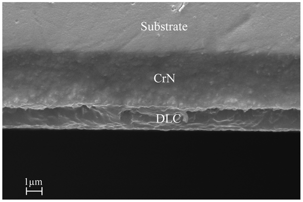
Transversal section of specimen A3
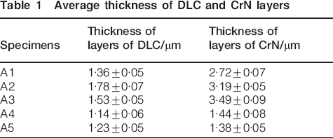
Average thickness of DLC and CrN layers
Instrumented indentation
Tests were carried out using an instrumented indention tester, model Fischerscope H100V, with a Vickers indenter. This equipment has a load range of 1 to 1000 mN and records the depth of penetration as a function of applied load. For each specimen, a total of 20 indentations with a load of 20 mN was performed.
Scratch tests
A diamond indenter (Rockwell C, tip radius of 200 μm) was used in the scratch tests, which were performed in an equipment designed and constructed by the Laboratory of Tribology and Materials (LTM), Federal University of Uberlândia (UFU).11 The scratch tester is shown in Fig. 2.
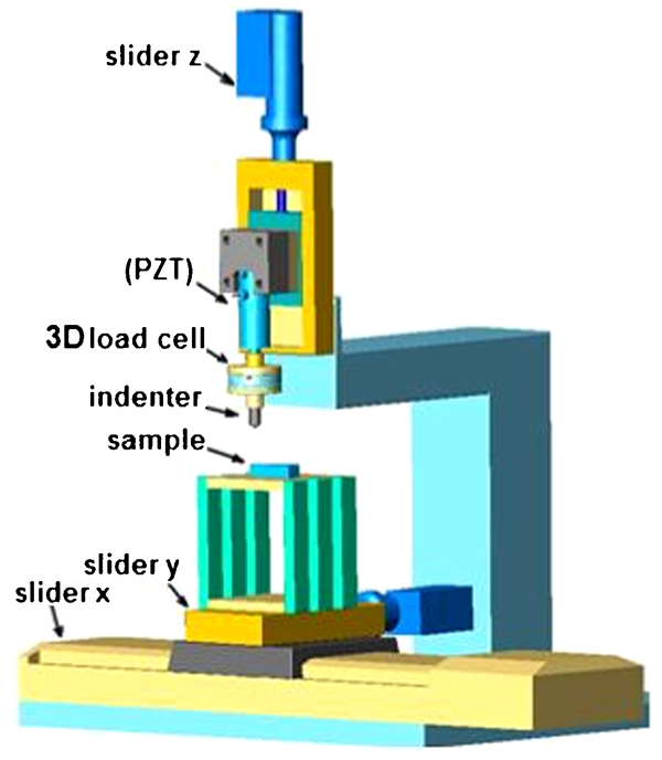
Scheme of microsimulator
In short, two high resolution (0·1 μm) sliders (slider x, slider y) drive the sample horizontally while the indenter is moved vertically by another slider (slider z), also with a resolution of 0·1 μm. Besides this, a piezoelectric translator (PZT) is used to control the indenter movement with a resolution of 5 nm for a maximum travel distance of 40 μm. A three-dimensional (3D) load cell controls the intensity of the normal load and measures the applied loads and moments in the directions x, y and z. The resolution of the load cell is 0·001 N and the maximum load is 18 N. A Labview interface was developed to control the movements of the sample and indenter.11
For specimens A1, A2 and A3, the normal force increased steadily up to 5 N. For samples A4 and A5, the maximum normal force was 15 N, since these coatings proved to be more resistant to spalling.
After the tests, the scratches produced were observed using scanning electron microscopy (SEM). The critical load for spalling was determined by matching the load measurements along the scratch with careful microscopic observation at different locations of the scratches.
Raman microspectroscopy
A Raman microscope, model Renishaw, using Argon laser with a wavelength in the range of 514 nm and laser power of 80% was used. Measurements were made in air at room temperature under a magnification of ×200.
After focusing the laser beam using a microscope, a scanning range of 100–3200 cm−1 was selected and three acquisitions were made using two accumulations in 10 s.
The parameters observed in the curves were: peak intensity, intensity ratio, position of the peak, full width at half-maximum and slope of the baseline. From these data, the following values were obtained: percentage of hydrogen (H%), intensities of the peaks D and G (ID, IG), the ratio ID/IG and the position of the peaks D and G.
Results and discussion
Instrumented indentation
Figure 3 shows the hardness of the DLC films as a function of the total thickness of the DLC/CrN films. The hardness decreased when the total layer thickness increased. A similar behaviour was observed for the elastic modulus, calculated by the method of Oliver and Pharr,12 as shown in Fig. 4.
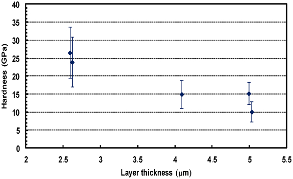
DLC hardness as function of total thickness
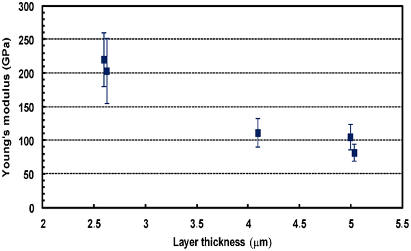
DLC elastic modulus as function of total thickness
A requirement for the method by Oliver and Pharr12 is that the phenomena called pile-up and sink-in should not occur. Pile-up consists of an accumulation of material at the edge of the indentation. Sink-in is characterised by the sinking of material along the indenter. The phenomena of sink-in and pile-up affect the contact area resulting respectively, in underestimation or overestimation of the contact area. The contact area is the main parameter to calculate hardness and modulus of elasticity from the results of an indentation test.
According to Oliver and Pharr,13 pile-up is negligible for hf/hmax<0·7, where hf is the final depth (the permanent depth of penetration after the indenter is fully unloaded) and hmax is the maximum displacement in the loading cycle. Otherwise, pile-up may or may not be significant, depending on the amount of strain hardening that occurred. Typical materials that have hf/hmax<0·7 are hard metals and ceramics. Table 2 shows values for the ratio hf/hmax, which were <0·7 for all the five specimens analysed.
hf/hmax ratios obtained in indentation tests
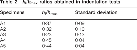
The literature shows that the hardness of a hard layer on a soft substrate is influenced by the substrate only if this ratio is greater than 20%.14–17 In this work, the ratio between the indentation depth and the thickness of the film was approximately 20%. It must also be emphasized that the intermediate CrN layer functions as a support for the DLC layer, reducing this effect. Additionally, recent work from our group18 showed that, in numerical simulations where the penetration depth was varied up to 50% of the film thickness, penetration depths of the order of 30% of film thickness may be used without large errors on hardness values.
Figure 5 shows the hardness values as a function of the applied load, where stabilisation occurred for the higher loads.
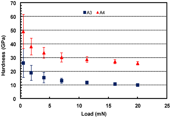
Hardness as function of load
This phenomenon, known as the indentation size effect (ISE), usually involves an increase in hardness with decreasing applied load and with decreasing indentation size. This effect has been attributed to various phenomena, including work hardening during indentation, indentation elastic recovery, size of dislocation loops formed during indentation, load to initiate plastic deformation, mixed elastic/plastic deformation response of material, strain gradients associated with dislocations and friction between the indenter and the specimen.19 Depending on the scale of the measurement (macro, micro and nano) and on the technique used, the influence of the substrate on the hardness value measured for the coating will be more or less significant. In this sense, Korsunsky et al.20 constructed a mathematical description of the hardness performance of coated systems which describes well their behaviour over this wide range of scales. They present a new approach to analyse hardness data using dimensionless parameters containing descriptors equally applicable to either plasticity or fracture dominated behaviour for all scales as a function of the coating thickness. In order to further understand this complex phenomenon, researchers are increasingly trying to rule parameters previously neglected, in particular instrumented micro and nano indentation, which have become popular methods to illustrate this dependence.21–29
Despite the low hardness of the substrate, hardness values between 10 to 26·5 GPa were found for the DLC layers. De Mello et al.30 analysed a similar CrN–Si rich DLC coated system and found hardness values varying between 12 and 19 GPa. The modulus of elasticity for the DLC varied between 81 and 220 GPa and Poisson's ratio was considered 0·30.
Scratch tests
The values of the critical load for occurrence of spalling LC, were determined following the scheme shown in Fig. 6. The load for the initial adhesion failure, identified by matching the microscopic observation of the scratch with the load measurements along the scratch, was called LC1, and the load for which total spalling occurred was called LC2.
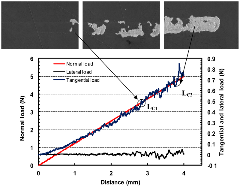
Critical load for specimen A1
Figure 7 summarises both critical loads for the five coated systems investigated in this work.
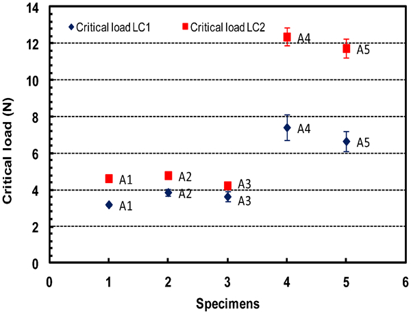
Spalling critical loads
Specimens A1, A2 and A3 showed intense removal of the film, characterised by material tearing and spalling, with a small plastic deformation of the surface. The indenter caused the lifting of small blades of the film at the interface of the coating with the substrate, which were subsequently moved laterally to the surface area. This was classified as an adhesive failure. The spalling of the coating is exemplified in Fig. 8 for specimen A1.
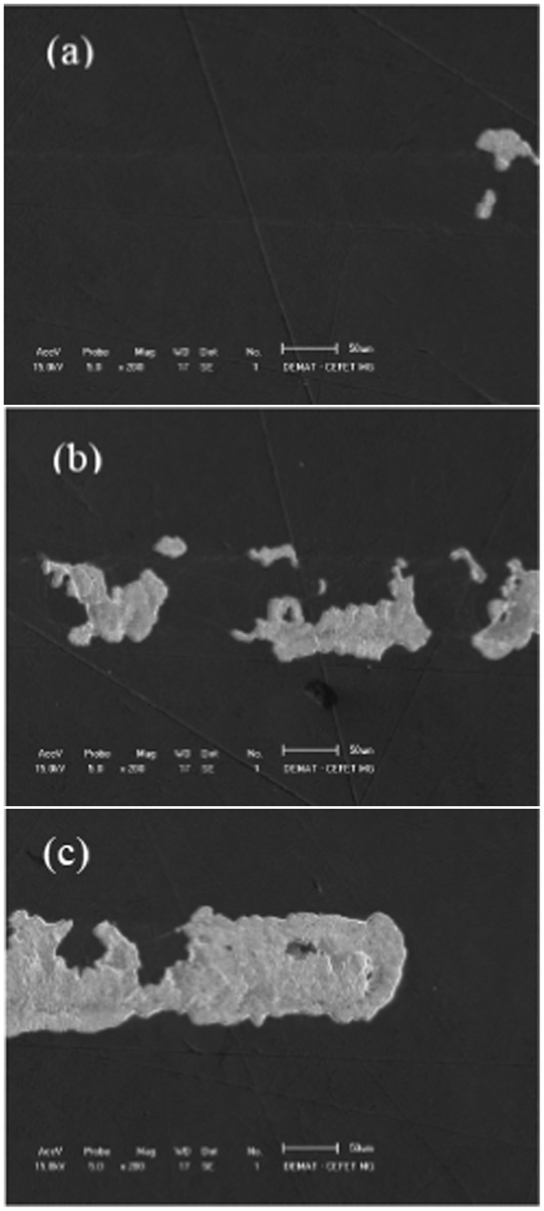
DLC film after scratch test. specimen A1: maximum load 5 N: a start of scratch; b middle of scratch, c end of scratch
Specimens A4 and A5 apparently showed cracks at the bottom of the tracks, which lifted chips from the coating, a typical cohesive failure. These chips were then deposited at the bottom of the tracks and/or placed laterally to the surface. However, the load of 5 N was not sufficient to cause spalling, as shown in Fig. 9 for specimen A4.
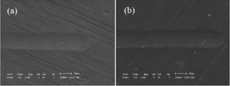
DLC film after scratch test: maximum load 5 N: a specimen A4; b specimen A5
Therefore, additional tests were carried out using maximum normal loads of 15 N, in order to obtain spalling for these specimens, as shown in Fig. 10.
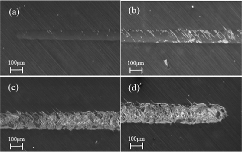
DLC film after scratch test specimen A4: maximum load 15 N: a start of scratch; b middle 1 of scratch; c middle 2 of scratch; d end of scratch
According to Bull et al.,31 the main factors affecting the critical load for adhesion failure during a scratch test are the substrate material, the coating thickness and the presence of residual stresses resulting from friction between the diamond indenter and the film. As the coatings tested have the same substrate in all cases, the largest contribution to the observed difference in adhesion between the films must be from the difference in coating thickness and from the level of residual stresses.
Raman microspectroscopy
In Raman spectroscopy, the spectra obtained for the DLC for the various thicknesses showed broad bands with peaks centred in the region of the D and G bands of graphite, proving that this is a film of amorphous carbon (Fig. 11).
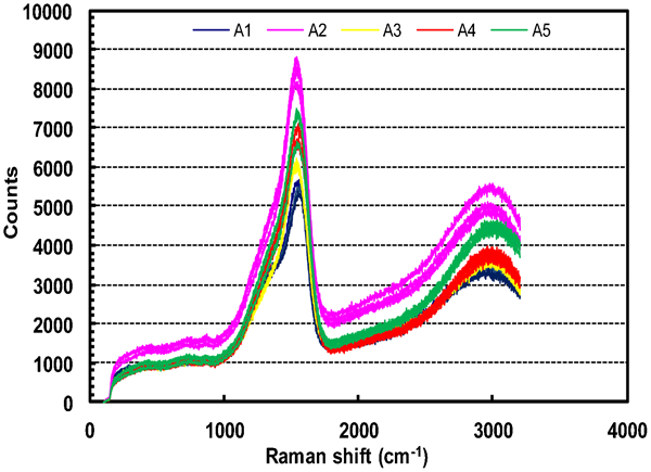
Raman spectroscopy
The differences between the Raman spectra for DLC films are not significant. They show two peaks typical for the DLC (G band at ∼1555±7 cm−1 and D band in 1380±7 cm−1). The intensity ratio ID/IG has small variations (0·60±0·08). There was not a considerable shift of the peak G, which suggests that there was no variation in the degree of disorder of the links between the carbons. Considerable variations were noted in the intensities of the peaks, which can be linked to different thicknesses of the DLC film.
According to Santos,32 larger film thickness requires higher deposition rates. The deposition of a thick film with a low deposition rate would increase the time necessary to obtain the DLC film, generating defects such as cracks and high residual stress. This effect occurs due to a restructuring of the DLC films, lowering the accommodation of three-dimensional carbon bonds during film growth, and therefore increasing residual stresses.
Hydrogen also has an influence on the nucleation of sp3 bonds. This type of hybridization is responsible for the mechanical properties of the film. However, a very high hydrogen content can lead to the appearance of a polymeric film, with low tribological interest. Therefore, the knowledge of hydrogen percentage in a DLC film is crucial.
The Raman spectroscopy analysis in this work showed a slight tendency for the specimens A1, A2 and A3 to have a hydrogen percentage higher than that of specimens A4 and A5. The first group has an average hydrogen content of 22·8±0·5%, and the second group of 20·7±0·7%.
Conclusion
Considerable variations in hardness and elastic modulus as a function of coating thickness were found in the instrumented indentation tests.
Critical loads determined in scratch test also showed a significant influence of coating thickness, where the highest critical loads were found for the thinner films.
Raman spectroscopy showed that differences between the Raman spectra for DLC films were not significant. The spectra obtained for various thicknesses showed broad bands with peaks centred in the region of the D and G bands of graphite, proving that it is a film of amorphous carbon.
This work shows that the coating thickness has an important role on the tribological response of the coated system.
Footnotes
Acknowledgements
The authors want to thank Pedro Shioga, Universidade Federal de Santa Catarina, Brazil for assistance in performing Raman analysis study. This research was supported by the Capes Foundation (Brazil).