
Abstract
In this article, the three body abrasive wear behaviour of long and short carbon fibre reinforced epoxy composites at five different fibre loading (10, 20, 30, 40 and 50 wt-%) has been evaluated. Three body abrasive wear tests are conducted to notice the effect of loss in weight of the specimen. The loss in weight of the material during three body abrasion can be tested using DUCOM Tr-50 Dry Abrasion Tester. The steady state specific wear of the composites can be evaluated for normal load and sliding speed by keeping other parameters constant. The results revealed that the wear rate increases with the increase in the value of normal load for long as well as short carbon fibre reinforced epoxy composites whereas, with the increase in the value of sliding velocity the specific wear rate decreases in both cases. Wear characteristics and their significant factor settings are successfully analysed using statistical methods, Taguchi experimental design and analysis of variance (ANOVA) respectively. Finally, the experimental wear rate results are compared with the theoretical one and the error lies within the acceptable limit i.e. for long carbon fibre composites the error values are within 8·11 and 5·56% for that of short carbon fibre composites. The SEM micrographs studies reveal the dynamics of three body abrasive wear and underlying micromechanisms that serve as determinant for wear performance of such composites.
Introduction
Fibre reinforced polymer matrix composite are increasingly used as a better substitute over conventional materials due to their desired mechanical properties. Fibre reinforced polymers are further classified as natural fibre reinforced polymer matrix composites and artificial fibre reinforced polymer sugarcane fibre, hemp fibre and bamboo fibre, etc. whereas artificial fibre includes glass fibre, carbon fibre and Kevlar fibre. Fibres short or long provide wear resistance, strength and transfer stresses whereas matrix glues the fibre together. Among commonly used resin such as epoxy, vinyl ester, polyester and PEK's, epoxy possesses excellent mechanical and tribological properties.1
Carbon fibre alternatively graphite fibre is a material consisting of extremely thin fibres about 0·005–0·010 mm in diameter and composed mostly of carbon atoms. Carbon fibres are made by aligning the graphite crystals in the direction of fibre. Several thousand carbon fibres twist and pile up in certain desired patterns to form bidirectional fabric and cut in particular length (5–8 mm) to form chopped carbon fibre. Carbon fibre reinforced polymer (CFRP) composite has been widely used in racing cars, aircraft parts and structure, X-ray table top, blades for wind mills, speed boats, CNG fuel tanks, golf shafts, robotic arms and structural material over the past two decades. The properties such as high strength to weight ratio, good rigidity, high temperature tolerance and low thermal expansion make them very popular for vast applications. Carbon fibres are a newly emerging and important class of structural material. Addition of graphite filler in carbon epoxy decreases the specific wear rate and volume loss while increasing the tribo performance of the composites significantly.2 Wear performance of aramid fabric is best followed by glass fabric and the lowest wear rate is for carbon fabric.3 Studies on the influence of fibre orientation with reference to wear direction revealed that lowest wear resistance is seen when the fibres are oriented normal to the plane i.e. 00 to the wear direction and highest wear is seen when the fibres are oriented parallel to the plane.4 Similar observations are noticed by Lhymn5 for unidirectional carbon fibre laminate PPS composite, wear rate followed the following order (Normal orientation<Anti parallel orientation<Parallel orientation).
Very low specific wear rate was observed for 00 orientations, while fibres in 900 showed that wear rate is approximately four times higher than in the earlier case. Overall fibre reinforcement in 00 orientation proved beneficial from both strength and triboperformance point of view.6 Bijwe et al.7 while investigating the wear performance of neat polyetheramide (PEI) with glass, carbon and aramid fabric noticed that aramid fabric improved the abrasive wear performance of PEI significantly and the wear rate was minimum if the fabric was in perpendicular direction to the sliding surface for glass, carbon and aramid fabric. Inclusion of CF in PEI deteriorated abrasive wear performance but improved friction performance at higher loads. Fibre orientation influenced both mechanical and tribological properties significantly. Fibres in direction parallel to loading/sliding proved more beneficial in both the cases. Fibres beyond 450 deteriorated the performance excessively.8
Experimental procedure
Materials selected
Bi-directional Carbon fibre (200 G.S.M, 3k-plain weave) and short carbon fibre (200 G.S.M. and 5 mm length) supplied by The Hindustan Technical Fabrics Limited, India are used as a reinforcing material. Fibre reinforced polymer composites of bi-directional and short carbon fibre are separately weighed for each weight percent (wt-%) composition and then mixed with epoxy resin chemically belonging to epoxide family used as a matrix material (chemical description is Bisphenol A Diglycidyl ether). The low temperature curing epoxy resin (LY556) and corresponding hardener (HY951) are mixed in the ratio of 10∶1 by weight as recommended. Epoxy resin and corresponding hardener are supplied by Ciba Geigy India Ltd. Carbon fibre and resin has young's modulus of 123 and 3·42 GPa respectively and possesses density of 1450 and 1100 kg m−3 respectively.
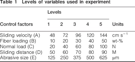
The bidirectional carbon fibres composite are prepared by a simple hand-lay-up technique which piles individual layers of fabric and resin one above the other until it reaches the required composition by weight of fibres that are being used. However, short carbon fibres are uniformly mixed with epoxy resin and then poured into a separate mould (moulds) for each weight percent fibre composition (i.e. 10, 20, 30, 40 and 50 wt-%) (Table 1). Prepared mould boxes are then placed for 24 h to get the proper curing. After that all the composites are removed from the mould and dried in a furnace at a temperature of 50°C for 15 min only to remove moistures from the composites.
Levels of variables used in experiment
Experimental details
Three body abrasive wear tests are carried out on long and short carbon fibre reinforced epoxy composites using DUCOM TR-50 dry abrasion tester according to ASTM G 65 test standards. A DUCOM TR 50 test instrument is designed such that a rectangular test sample (75×25·4×12·7 mm) fixed inside the specimen holder (Figure 1). Abrasive media (silica sand) flows freely in between the rubber wheel and the test specimen such that the wheel carries the abrasive particles in between the wheel and the test specimen creating a scenario of three body abrasive wear (flowrate of abrasive particles is 358 gms min−1). When desired normal load applied on the specimen, the latter comes in contact with the rubber wheel; the abrasive media carried by the rubber wheel penetrates inside the specimen and in turn removes material from the contact surface of specimen. The difference in weight of the test samples denotes the wear rate of the specimen.
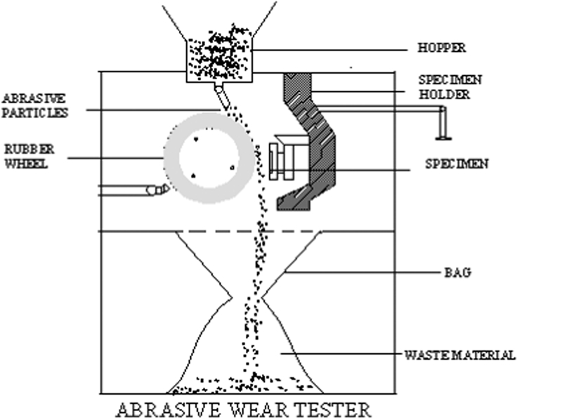
Experimental set-up for abrasive wear test rig
The loss in volume of sample is computed in the following manner
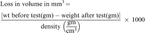
The specific wear rate WS was calculated experimentally from the equation

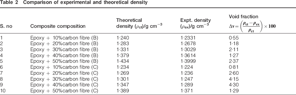
Comparison of experimental and theoretical density
Test for theoretical density
The theoretical density of composite material in terms of weight fraction can easily be calculated with the help of Agarwal and Broutman9 equation. The difference in the values of theoretical and experimental density is a measure of the presence of voids and pores in the composites. The void fraction is calculated as given by

The surfaces of bidirectional as well as chopped Carbon fibre are examined by using scanning electron microscope (Carl Zeiss NTS GmbH, SUPRA 40VP). The composite samples are mounted on stubs and photomicrographs are taken for each composition at different amplification ranges for analysis and study.
Experimental design
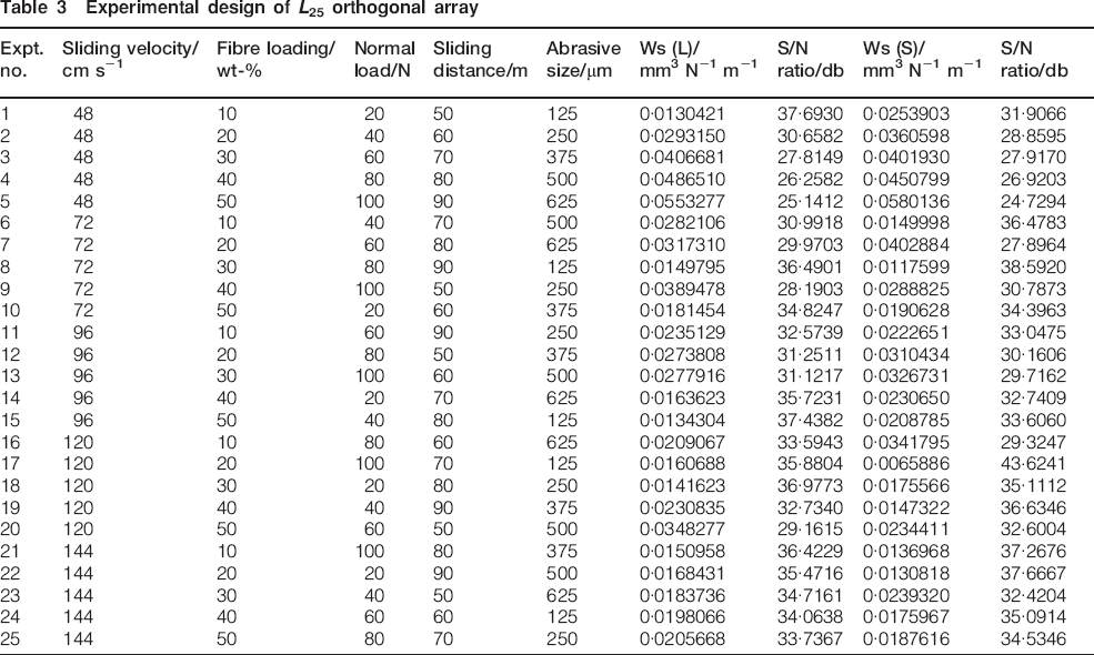
Optimisation of process parameters is a key step in experimental design. This is because optimisation of process parameters can improve quality and the optimal process parameters obtained from the Taguchi method can help us in deciding the best design. Basically classical process parameter design is complex and not easy to use.10 An advantage of the Taguchi method is that it emphasizes the mean performance characteristic value close to the target value rather than a value within certain specification limits, thus improving the quality.11 A large number of experiments have to be carried out when the number of the process parameters increase. To solve this task, the Taguchi method uses a special design of orthogonal arrays to study the entire process parameter space with only a small number of experiments.12 Here the Taguchi method experimental approach is used to find optimum parameters from given five variables, namely, fibre content, normal load, sliding distance, abrasive size and sliding velocity as shown in table and each at five labels. The impact of five such parameters is studied using the L25 (55) orthogonal array design. The Taguchi factorial experimental approach reduces the number of experiments to 25 runs, which in turn results in great reduction in time and cost. The experimental observations are further transformed into signal to noise (S/N) ratios. For bidirectional and chopped carbon fibre there is a separate signal-to-noise ratio for each iteration. The S/N ratio for minimum three body abrasion can be expressed as ‘lower is better’, which is calculated as logarithmic transformation of loss function as shown below
The plan of experiments is as follows: the first column is assigned to fibre loading (A), second column to filler content (B), third to normal load (C), fourth to rotation speed (D) and fifth to sliding distance (E). Finally a confirmation experiment is conducted to verify the optimal process parameters obtained from the parameter design.
Results and discussion
Physical properties are measured to notice the effect of prepared compositions on the overall performance. Effect of increase in percentage by weight of fibre/fabric composition on specific wear rate of composites is discussed. Analysis also includes comparison in properties of bidirectional CFRE composites to that of chopped CFRE composites.
Effect of void content on bi-direction/chopped short carbon epoxy composites
Void content measures the voids in reinforced polymers and composites. Information on void content is useful because high void contents can significantly reduce composite strength. For measuring void content it is necessary to have the theoretical densities of both the resin and the reinforcing material. Table 2 shows the experimental and theoretical observed densities for CFRE composites. The values of experimentally observed densities are somewhat less than that of theoretical densities. The difference is a measure of pores and voids in the composite and it usually varies from 0·5564 to 2·3779% for bidirectional carbon fibre and from 0·8103 to 4·3058% for chopped carbon fibre. It was observed from the comparison in density of bidirectional and chopped carbon fibre reinforced composites (Table 2) that the void content in chopped CFRE is more than that of bidirectional CFRE as inhomogeneous mixing and improper pressing increased chances of air entrapment in chopped CFRE composites. Similar observations were obtained by Bijwe et al.7 while investigating the abrasive wear performance of carbon fabric reinforced polyetheramide composites.
Steady state specific wear
The specific wear rates can be used as a guide in ranking the wear resistance of composite materials. The specific wear rate is not a material property and will therefore differ with test conditions and test geometries. Materials with superior wear resistance have lower specific wear rates.
Effect of sliding velocity on specific wear rate for bidirectional (long) CFRE composites
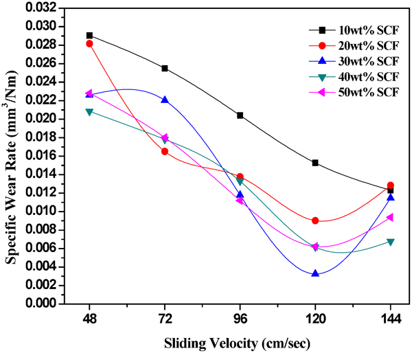
Figure 2 shows the behaviour of change in specific wear rate with the change in sliding velocity keeping other variables constant. Here five variables, i.e. normal load, sliding velocity, sliding distance, abrasive particle size and percentage by weight of fibre loading (wt-% composition) are taken into consideration to notice the effect of sliding velocity on specific wear rate of bidirectional CFRE composites. Figure 2 shows that specific wear rate decreases with the increase in sliding velocity. The decrease may be attributed to the fact that at higher speeds the contact time between the surface of the rubber wheel and the specimen decreases therefore less number of abrasive particles are embedded inside the surface of the specimen which in turn removes less amount of material in the form of chips at the time of detachment and therefore specific wear rate decreases. Similar observations were noticed by Gaurav et al.13 for sliding velocity of bidirectional GFRE composites.
Effect of sliding velocity on specific wear rate of long carbon fibre reinforced epoxy composites (at constant normal load: 40 N, sliding distance: 60 m and abrasive size: 375 μm)
Effect of normal load on specific wear rate for bidirectional (long) CFRE composites
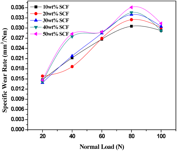
Experiments carried out to notice the effect of normal load on specific wear rate on bidirectional carbon fibre reinforced epoxy composites. Normal load vary in steps of 20 N from a minimum of 20 N to the maximum of 100 N for 10, 20, 30, 40 and 50 wt-% fibre reinforcement. Figure 3 shows the effect of normal load on specific wear rate of the composites. The value of specific wear rate increases in steps with the increase in the values of normal load on the specimen up to 40 wt-% fibre composition and beyond 40 wt-% fibre loading specific wear rate slightly deceases. This increase may be attributed to the fact that as the normal load increases more pressure is induced normal to the surface of the specimen resulting in more surface contact with the rubber wheel. Abrasive particles penetrate inside the specimen within this contact surface and hence weight loss and specific wear rate increases.
Effect of normal load on specific wear rate of long carbon fibre reinforced epoxy composites (at constant sliding velocity: 72 m s−1, sliding distance: 60 m and abrasive size: 375 μm)
Effect of sliding velocity on specific wear rate of Chopped (short) CFRE composites
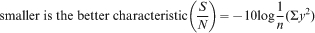
Figure 4 shows the effect of change in sliding velocity on specific wear rate of the short Carbon fibre reinforced epoxy composites keeping normal load: 40 N, sliding distance: 60 m and abrasive size: 375 μm as constant. Specific wear rate decreases with the increase in sliding velocity of short CFRE composites. This is due to the fact that the surface area of contact is similar for all sliding velocities (constant normal load) whereas the duration of contact reduces as the sliding velocity increases It is further noticed that specific wear rate at 10 wt-% fibre composition is maximum. Minimum values of wear rate are measured for 40 and 50 wt-% fibre composition. However, at 10 wt-% fibre composition quantity of epoxy resin is more in comparison to that of reinforcing fibre. The wear rate is faster at 10 wt-% fibre loading than that at higher wt-% composition.
Effect of sliding velocity on specific wear rate of short carbon fibre reinforced epoxy composites (at constant normal load: 40 N, sliding distance: 60 m and abrasive size: 375 μm)
Effect of normal load on specific wear rate of chopped (short) CFRE composites
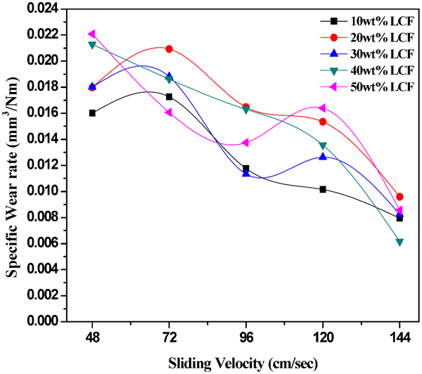
A number of experiments have been conducted to notice the effect of change in normal load on specific wear rate of chopped CFRE composites. Figure 5 shows that the specific wear rate increases with the increase in the values of normal load. Increase in the values of specific wear rate is directly proportional with the increase in the values of normal load up to 40 wt-% fibre composition, further the values of specific wear rate is inversely proportional to the increase in specific wear rate. This increase in the values is as discussed in normal load for bidirectional CFRE composites. Decrease in the values is due to the weaker interface between the fibre and the matrix resulting in detachment of material from the surface of the specimen and hence specific wear rate decreases.
Effect of normal load on specific wear rate of short carbon fibre reinforced epoxy composites (at constant sliding velocity: 72 m s−1, sliding distance: 60 m and abrasive size: 375 μm)
Analysis of experimental results by Taguchi experimental design
In Table 3, the eighth and tenth columns represent S/N ratio of the specific wear rate of the composites which is in fact the average of two replications. The overall mean for the S/N ratio of the specific wear rate is found to be 32·75 db for bi-directional carbon fibre reinforced epoxy based composites and 32·88 db for the chopped carbon fibre reinforced epoxy based ones. The analysis was made using MINITAB 15 software used for design of experiment of applications. It is observed that the abrasive result leads to the conclusion that factor combination of A5, B1, C1, D4 and E1 gives minimum specific wear rate (Fig. 6) for bi-directional carbon-epoxy composites and for short carbon epoxy composites the factor combination of A4, B1, C1, D3 and E1 gives minimum specific wear rate (Fig. 7). Table 3 presents the specific wear rate of bi-directional carbon epoxy composites and compares them with the results for chopped carbon epoxy composites. It is observed that for similar test conditions chopped glass epoxy composites exhibits much lower wear rates than those by bi-directional carbon epoxy composites. This establishes chopped carbon epoxy as a better candidate for reinforcement as compared to bi-directional carbon epoxy from wear response point of view.
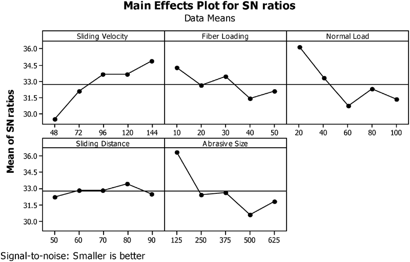
Effect of control factors on signal-to-noise ratio of long carbon fibre reinforced epoxy composite
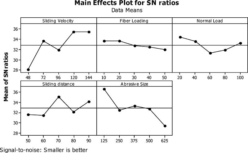
Effect of control factors on signal-to-noise ratio of short carbon fibre reinforced epoxy composite
Experimental design of L25 orthogonal array
Surface morphology
Scanning electron microscope (SEM) micrographs have been taken to notice the wear surface details of bidirectional and chopped carbon fibre reinforced epoxy composites. Figure 8a represents the surface details of bidirectional 20 wt-% CFRE composites (sliding velocity 96 cm s−1, normal load 80 N and abrasive particle size 375 μm and magnification 200X). Top layer of fibres perpendicular to the wear direction wore out during three body abrasion and the bottom layer (second layer) of fibers are exposed to the environment. It has been observed that the layers of fibres perpendicular (900) to the wear direction are removed faster than the layer of fibres parallel (00) to the wear direction if other parameters remain constant. Surface irregularity represents the presence of extra material (fibres+epoxy) due to adhesion on the surface of the specimen. Figure 8b represents the surface details of CFRE composites at 40 wt-% fibre loading, sliding velocity 96 cm s−1, normal load 20 N and abrasive particle size 625 μm. Micrograph at ×500 magnification reveals the presence of remaining layer of material, left out parts of fibre and epoxy removed during three body abrasion.
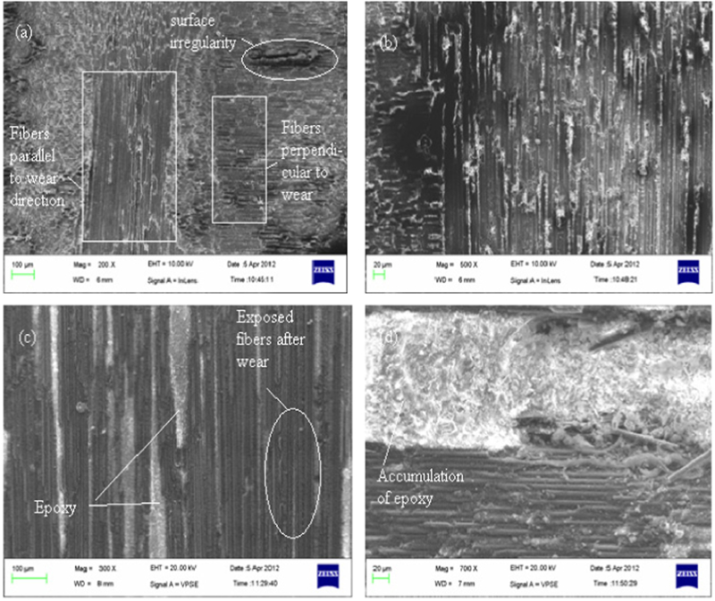
Images (SEM) showing surface details long and short carbon fibre reinforced epoxy composites
Figure 8c shows the surface micrograph for 20 wt-% chopped carbon fibre reinforced epoxy composite at ×300 magnification, 120 cm s−1 sliding speed, 100 N normal load and 125 μm abrasive particle size. After three body abrasion intermediate layer of fibres are exposed to the environment. Details show that (Fig. 8c) the end of fibres or some portions of fibre are removed during abrasion process. This is because when abrasive particles (silica sand) penetrate inside the specimen, parts of the fibres are chipped off during disengagement of particles from the surface. Parts of epoxy resin left after abrasion process are also relevant from the micrographs. Figure 8d shows the surface details of CFRE composites at 40 wt-% fibre composition, 120 cm s−1 sliding velocity, 40 N normal load, 375 μm abrasive particle size and at ×700 magnification. Surface micrograph shows the accumulation of a huge amount of epoxy resin at one place. This is because fibres and epoxy are mechanically stirred before solidification in mould and this increases the chances of accumulation of fibres and resin (epoxy) at one place.
Scanning electron micrographs of the abraded surface is shown in Fig. 9 tested under different three body abrasive wear conditions. Figure 9a shows results of 20 wt-% bidirectional CFRE composite tested under given conditions (sliding velocity 96 cm s−1, normal load 80 N and abrasive particle size 375 μm). Severe damage has been observed to matrix material leading to exposed fibres on the surface. These exposed fibres tend to fracture which results in their removal from the surface of the specimen. Figure 9b shows the SEM micrograph for 30 wt-% bidirectional carbon fibre reinforced epoxy composite (sliding velocity 144 cm s−1, normal load 40 N and abrasive particle size 625 μm). Parts and ends of fibers are chipped of during three body abrasion resulting in more amount of material removal from the surface. Material is removed in the form of chips and small particles entered inside the hollow cavities created during fabrication or uneven removal of material during three body abrasion from composite specimen. Figure 9c represents the surface photomicrograph for 40 wt-% bidirectional CFRE composites taken at ×20 000 magnification, sliding velocity 96 cm s−1, normal load 20 N and abrasive particle size 625 μm. Surface details of fibre subjected to three body abrasive wear shows the mechanism of fibre matrix debonding when matrix material (resin) removed from the surface of the fibres. The fibre matrix debonding depends on the orientation of fibres, mainly in the direction of wear. When fibres are oriented parallel to wear direction the fibre – matrix debonding is due to the applied load of second body (abrasive media) on the fibres due to which fibres move aside whereas in perpendicular orientation this is due to the possible bending of the fibres. Longitudinal wear scars on the surface of the fibre is due to the movement of abrasive particles abrading the surface of specimen. Figure 9d shows the photo micrograph of the abraded surface taken for 40 wt-% fibre loading, sliding velocity 96 cm s−1, normal load 20 N abrasive particle size 625 μm. Owing to higher sliding velocity the matrix wear related to fibre movement takes place i.e. matrix removal takes place due to pressure induced by the moving of fibre. Owing to bigger size of abrasive particle size stress developed is more and due to higher stress fibres are subjected to brittle fracture and hence specific wear rate increases.
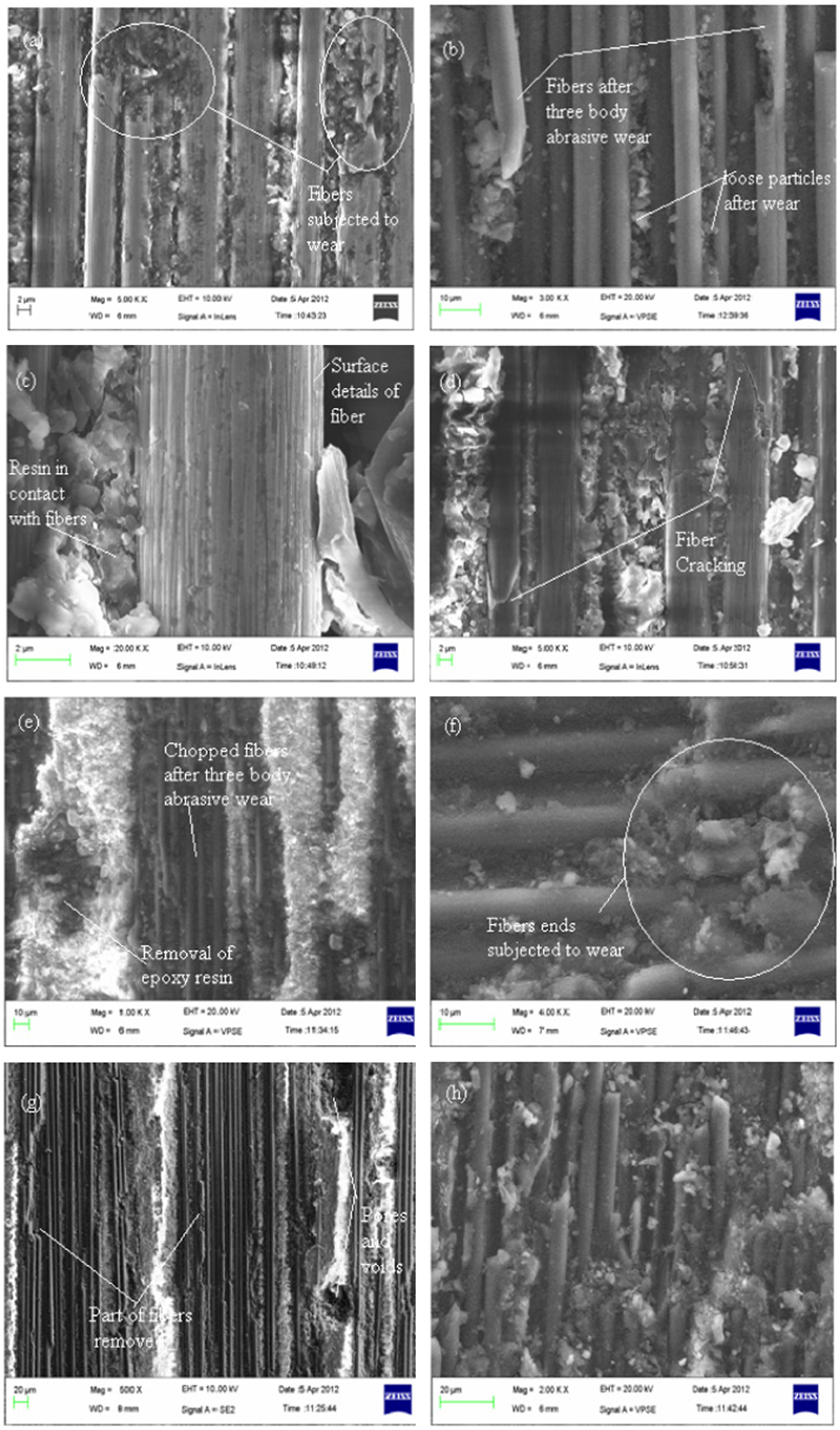
Images (SEM) showing fibre details of long and short carbon fibre reinforced epoxy composites
Figure 9e shows the SEM surface details of 20 wt-% short Carbon fibre reinforced epoxy composites taken at sliding velocity 120 cm s−1, normal load 100 N and abrasive particle size 125 μm. As the normal load increases wear rate increases but this higher normal load is compensated by smaller abrasive particle size and higher sliding velocity which results in decrease in wear and hence specific wear rate is 0·006588 mm3 N−1 m−1. Also the uneven removal of material is due to higher normal load and higher sliding velocity (i.e. short abrasion time). Figure 9f shows photomicrographs for the abraded samples at 40 wt-% fibre loading, 120 cm s−1 sliding velocity, 40 N normal load and 375 μm abrasive particle size. Due to random orientation, fibres are oriented at 45° to the wear direction. Wear rate at 45° orientation is higher than the wear rate at 0° orientation (parallel to wear direction). Since when the fibres are oriented at 45° to wear direction wear thinning is minimal and fibre cutting is maximum leading to very high wear. Deterioration in fibre matrix bonding followed by fibre microcracking, microcutting leading to pulverisation, removal of material from the matrix in the form of debris are clearly seen from the surface micrographs. Figure 9g shows the surface details of 20 wt-% chopped carbon fibre reinforced epoxy composites (sliding speed 120 cm s−1, normal load 100 N and abrasive particle size 125 μm). The above Fig. 9g clearly shows wear tracks as a result of three body abrasive wear. Ends of fibres are removed due to the continuous rubbing action of abrasive particles on the surface of the workpiece when placed against rotating rubber wheel. Pores and cavities are clearly seen on the surface of chopped fibre composite. Since the void fraction at 20 wt-% fibre composition is highest among all compositions (bidirectional and chopped) as shown in Table 1. Therefore the presence of cavities on the surface of the specimen is clearly visible from the micrographs.
Figure 9h shows the surface details of chopped carbon fiber reinforced epoxy composites at 30 wt-% fibre loading, sliding velocity 96 cm s−1, normal load 100 N and abrasive particle size 500 μm. Owing to higher normal load acting in between the surface of the rubber wheel and the specimen, area of contact of the specimen with the rubber wheel increases and the larger size of abrasive particles (silica sand) penetrates inside the contact area creating large amount of wear.
ANOVA and effects of factors
Analysis of variance (ANOVA) based on Taguchi experimental results is performed in order to find out statistical significance of various factors like sliding velocity, fibre loading, normal load, sliding distance and abrasive size on specific wear rate of the long and short carbon fibre reinforced epoxy composites. Experimental analysis of ANOVA is done using MINITAB 15 software. Tables 4 and 5 show the results of the ANOVA with the specific wear rate of bi-directional and short carbon epoxy based composites taken in this investigation. This analysis is undertaken for a level of confidence of significance of 5%. The last column of the table indicates that the main effects are highly significant (all have very small p-values) (Table 4, Column 7).
ANOVA for specific wear rate (bi-directional carbon fibre)*
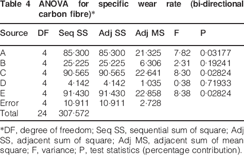
*DF, degree of freedom; Seq SS, sequential sum of square; Adj SS, adjacent sum of square; Adj MS, adjacent sum of mean square; F, variance; P, test statistics (percentage contribution).
ANOVA for specific wear rate (short carbon fibre)*
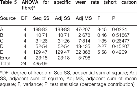
*DF, degree of freedom; Seq SS, sequential sum of square; Adj SS, adjacent sum of square; Adj MS, adjacent sum of mean square; F, variance; P, test statistics (percentage contribution).
From Table 4, it can be observed for bi-directional (long) carbon epoxy based composites that sliding distance (p = 0·71933) and fibre loading (p = 0·19241) have a great influence on specific wear rate. However normal load (p = 0·02824), abrasive particle size (p = 0·02824) and sliding velocity (p = 0·03177) shows less significant contribution on specific wear rate of the composites.
Similarly, from Table 5, it can be observed that for short carbon fibre reinforced epoxy composites fibre loading (p = 0·51867), normal load (p = 0·26477) and abrasive particle size (p = 0·4209) have great influence on specific wear rate. The remaining factors i.e. sliding velocity (p = 0·0224) and sliding distance (p = 0·15207) have less significant effect on the specific wear rate of the composites. Therefore, from this analysis it is clear that short carbon epoxy composites are more suitable for abrasive wear environment as compared to that of long carbon epoxy composites. However, for a structural application point of view long carbon fibre reinforced epoxy composites show better mechanical properties than short carbon fibre reinforced epoxy composites.
Calculations of theoretical results and comparison with experimental results
Number of experiments is being carried out to notice the effect of steady state three body abrasive wear and Taguchi's design of experiments for different percentages of fibre and epoxy resin. A L25 array is being selected to test for optimum wear rate and specific wear rate. The experimental values are then compared with that of the theoretical ones14 and an error percentage is calculated. Therefore, the theoretical specific wear rate of the composites is calculated by using equation 5 for three-body abrasive wear rate as

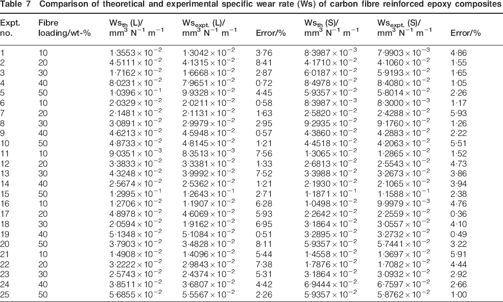
The developed theoretical predictive results for specific wear rate (Ws) of long and short carbon fibre reinforced epoxy composites are calculated using equation 5. From the equation it is evident that specific wear rate is directly proportional to coefficient of friction, percentage of fibre reinforcement and length of fibre whereas inversely proportional to hardness of the composite and percentage length for elongation to break of fibre. Here length of fibre (L) selected for long carbon fibre is 20 cm as the composite are prepared for 20 cm length×20 cm width whereas the elongation to break selected is 1·9% of the length of fibre as per the specifications given by the supplier (Hindoostan Technical Fabrics Limited) whereas when the length of short carbon fibre is 5 mm and elongation to break is 1·9% of the length of the short fibre. Coefficient of friction (μ) is the ratio of frictional force to the normal load. Values of frictional force, normal load and hardness are given in Table 6. These theoretical values are compared with the values obtained from experimental results conducted under similar operating conditions. Table 7 presents a comparison between experimental results and theoretical results. The errors in experimental results are compared with theoretical results for long and short carbon fibre reinforced epoxy composites. Errors lie in between 0·51 and 8·41% for long carbon fibre (Table 7) and 0·36–5·93% for short carbon fibre (Table 7).
Calculation of theoretical specific wear rate of carbon fibre reinforced epoxy composites*
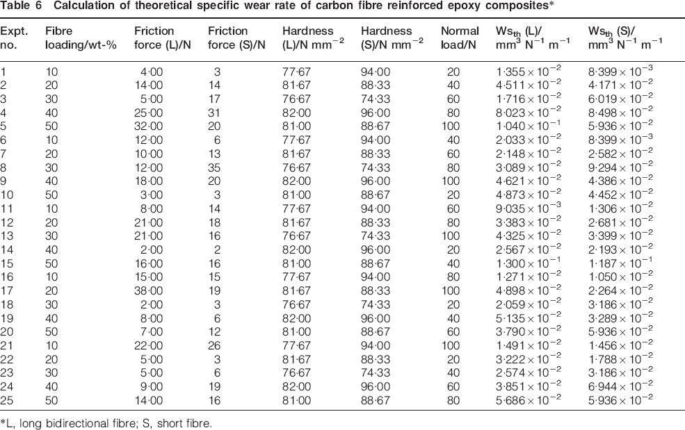
*L, long bidirectional fibre; S, short fibre.
Comparison of theoretical and experimental specific wear rate (Ws) of carbon fibre reinforced epoxy composites
Conclusion
A comparative study has been carried out on long and short carbon fibre reinforced epoxy composites to notice the effect of three body abrasion (based on several factors) on the specific wear rate of composites. Based on the above observations, the following points may be concluded as under.
Specific wear rate changes with the change in sliding velocity and normal load of the composites. With the increase in sliding velocity specific wear rate decreases whereas specific wear rate increases with the increase in normal load for both bidirectional and chopped carbon fibre reinforced composites.
Taguchi design of experiments is used to calculate minimum specific wear rate for the given set of five factors each having five variables. The minimum specific wear rate for long carbon fibre reinforced composites is for A5, B1, C1, D4, E1 whereas for short carbon fibre minimum specific wear rate is for A4, B1, C1, D3, E1. Since the specific wear rate values for short carbon fibre composites are less in comparison to that of long carbon fibre composites therefore short carbon fibre reinforced epoxy composites is better choice (where A, B, C, D and E are the factors and 1, 2, 3, 4 and 5 are levels).
Analysis of variance (ANOVA) based on Taguchi experimental results are performed in order to find out statistical significance of various factors. It has been observed that fibre loading and sliding distance have more significant effect on specific wear rate of bidirectional CFRE whereas for short CFRE composites fibre loading and abrasive particle size have more significant effect.
Theoretical values of specific wear rate are calculated based on the given wear model and further compared it with experimental specific wear rate values. The errors values for long carbon fibre reinforced epoxy composites lies within the range of 0–8%. Whereas for short carbon fibre reinforced epoxy composites error values are in the range of 0–5% error.
On comparison of theoretical density with that of experimental density for bidirectional and chopped carbon fibre reinforced epoxy composites it is noticed that theoretical density is higher than that of experimental density. For bidirectional CFRE composites the void percentage is between 0·55–2·37% whereas for short CFRE composites void percentage lies in between 0·81–4·30%.
SEM micrographs revels that matrix material (epoxy resin) chips of faster than that of carbon fibers. Also it has been observed that with the increase in normal load the ends/parts of fibres are subjected to cracks and removal.
Future study can be extended to new fiber/matrix combinations and the resulting experimental findings can be further analysed similarly.