
Abstract
Atomic force microscopy (AFM) allows one to examine the effects of applying highly localised stress to a surface. In the presence of solutions, tribochemical friction and wear can be investigated. We present the results of fundamental studies of the simultaneous application of chemical agents and mechanical stress using a single asperity model and a solid surface. At the same time, we show the consequences of combining highly localised mechanical stress (due to contact with AFM tip) and exposure to solutions of known pH. The experiment simulates several features of a single particle–substrate–slurry interaction in chemical mechanical polishing (CMP). To optimise CMP process, one needs to get information on the interaction between the abrasive slurry particles and the surface being polished. To study such interaction, we used AFM. Surface analysis of selective layer using the AFM revealed detailed surface characteristics obtained by CMP. In studying the selective layer CMP, which is predominated by copper (in proportion of over 85%), we found that the AFM scanning removes the surface oxide layer in different rates depending on the depth of removal and the pH of the solution. It was found that removal mechanisms depend also on the slurry chemistry, potential, percentage of oxidiser and the applied load. We show that linear and raster scans display significantly different material removal rates. Oxide removal happens considerably faster than the copper CMP removal from the selective layer. This is in agreement with generally accepted models of copper CMP. Quantitative models are presented to explain the observed nanometre scale surface modifications. Both load force and the friction forces acting between the AFM tip and surface during the polishing process were measured. One big advantage of using the AFM tip (of radius of ∼50 nm) as abrasive silica particle is that we can measure forces acting between the particle tip and the surface being polished. Here, we report measurement of the friction force while scratching and polishing. The correlation between those forces and the removal rate is discussed. At the same time, this paper complements recent observations of tip induced wear and growth in a number of inorganic surfaces in solution.
Keywords
Introduction
Among other planarisation technologies, chemical mechanical polishing (CMP) is a unique global planarisation technology, which makes it to be continuously investigated. Chemical mechanical polishing is used to remove the excess of metal obtained in selective transfer process and to improve the polishing and micromachining. Chemical mechanical polishing is the technology that ensures pattern formation with higher resolution and the surfaces with higher planarity. The polishing and micromachining are of considerable interest to different engineering fields, such as the friction couples that function with selective transfer. Indeed, CMP seems to be the only effective technique to achieve both local and global planarisation used in modern manufacturing.
It is known that in the process of friction of two materials and in the presence of own lubricants, the wear phenomenon manifests as a transfer of material from an element of a friction couple on the other, this phenomenon being a characteristic to the selective transfer process. A selective transfer can be safely achieved in a friction couple if there is a favourable energy and in the presence of relative movement; if in the friction area, the material is made by copper; and the lubricant is adequate (glycerin or special lubricant). 1, 2 The forming selective layer on the contact surfaces makes the friction force very low because of the structure formed by selective transfer.
To understand the surface properties of layers formed by selective transfer at the nanoscale, it must be specified that there are materials that, in optimal functioning conditions, form a thin, superficial layer of copper in the contact areas, therefore can function in conditions a selective transfer. These materials have in common the fact that, in the friction areas, special physical–chemical processes take place, which leads to the forming of a thin copper layer, with superior properties at minimal friction and wear.1–5 This is a criterion for any friction couple of high efficiency and normal process for the self-adjustment phenomena.
It is well known that the friction resistance between solids is reduced significantly if they are lubricated, and in conditions of selective transfer, the thin layer of copper plays the role of the lubricant.
The removal of a soft oxide film enables better planarisation. 6 In many cases, our understanding of material removal mechanisms is largely empirical. Nevertheless, it is clear that the material removal often involves chemical as well as mechanical stimuli.
Copper CMP studies in acidic and basic slurries were conducted in the past. Current achievements in the study of copper CMP are reported in different papers.7–11 Yet, the synergy of electrochemical, mechanical and tribochemical interactions is important to been understood.
To optimise the process of copper CPM from a selective layer, various chemicals, abrasives, polishing pads, etc. have been investigated. However, due to the many parameters that can influence the CMP process, optimisation of CMP by experimental means has been difficult. Modelling selective layer CMP can help rationalise CMP optimisation. To increase the effectiveness of modelling, one must know the behaviour of the pad, wafer surfaces and their interaction with the abrasive particles. 12 The technique that is capable of measuring such information is atomic force microscopy (AFM). We show here that the AFM technique can be used to study selective layer CMP under various conditions. Furthermore, to improve modelling, it is useful to study the mechanical/physical part of CMP separately from the chemical aspects. By applying the slurry chemicals to the selective layer surface for some period of time and then removing the oxidising agent from the slurry, we can study the mechanical action of the abrasives on the oxide layer separately from the chemical action. An AFM tip of radius of ∼50 nm was used to mimic a single abrasive silica particle typical of those used in the CMP slurry. During AFM scanning, the particle-like tip moves over the surface being polished with a relatively high load force. This induces scratching the surface akin to the CMP process. The AFM is used for both scratching while operating with a high load force and imaging while scanning with a small load force.
At high contact forces, friction and wear can be induced by the tip of an AFM. Under these conditions, the AFM serves as an especially simple friction and wear system involving a single asperity translated across a well characterised surface.
In recent papers, we have characterised the friction and wear of silicon nitride tips on selective layer surfaces in solutions. 11, 13 In this paper, we monitor the friction and wear of the selective layer substrate in basic solution. As one might expect, the friction and wear of the AFM tip affect that of the underlying substrate. An understanding of nanometre scale friction and wear must incorporate the mutual removal of material from asperity and substrate.
Experimental
A Dimension 3100 Nanoscope AFM by Digital Instruments was used in this study. Standard integrated silicon nitride pyramidal shaped AFM tips by Digital Instruments were utilised for the AFM ‘scratching and polishing’. Nanoprobe silicon rectangular cantilever tips were used for the measurements of friction forces. Spring constants of both types of cantilevers were measured, and they have k of ∼0·15 N m−1 (it was determined by resonance method using built-in option in the AFM software).
Slurry solution used for copper oxidation from the surface of selective layer was prepared as aqueous solution of 5 wt-% peroxide and 1 wt-% glycine in different pHs of 3, 4, 5, 6, 7, 8, 9, 10 and 10·5. The pH of the slurry was adjusted with either HCl or KOH with 10 mM ionic strength. Oxidation of the copper from the surface selective layer was carried out by placing of about 2–3 cm diameter droplet of the slurry solution onto the selective layer surface for 10 or 15 min. The AFM scanning/scratching was carried out with no oxidising agents, and took place in aqueous solutions of HCl and KOH of 0·01 mol L−1 mixed to maintain the same pH as in the slurry solution.
The copper potential (it is the potential with respect to open circuit potential) from the selective layer was varied from anodic to cathodic side. Surface characterisation using an AFM was conducted after CMP under the same conditions of potential. The slurry composition parameters and their values are given in Table 1.
Values of parameters slurry

The surface morphology and friction response to AFM probes were studied for the revelation and intuition of tribochemical mechanisms. The AFM scanning was carried out over 6×6 μm area smoothed by 10 square scans, with a load force of about 20–30 nN at 512 lines/scan. This is about the estimate a force for a single abrasive particle during CMP (this force can also be estimated as a result of the pressure of the order of 10 lb in−2 was spread over particles of slurry that contain 5% abrasives). 14, 15 The scan rate was 360 nm min−1 = 6 nm s−1, which has met the industry requirement (more than 300 nm min−1 = 5 nm s−1). The reported results were collected only for the cases when the tip wear was negligible.
Time of polishing was calculated as follows. During scanning/scratching, each line along the surface was scratched twice, e.g. right and left by AFM tip for some period of time (fast scanning/scratching direction). After each fast scan, the tip moves slowly in perpendicular direction (slow scanning direction). The amount of each shift of the tip in slow direction was determined by the AFM software and is equal to the linear of the scan divided by 512. Thus, the actual polishing time for each line on the surface (in the fast scanning/scratching direction) was less than the total scanning time of entire square region. The polishing time used here was calculated as the time of scanning/scratching of each line of the surface by the AFM tip. Such a polishing time is more convenient for comparison with the CMP data than just the tip simple contact time. Thus, one scan of 6×6 μm area with 10 Hz fast scan speed took ∼31·25 s. How the area was smoothed by 10 square scans results to a total scanning time of 312·5 s.
Results and discussion
Atomic force microscopy topography scans were used to find the surface roughness Ra values for the scanned areas. The observed Ra values were considered as an index for polishing quality after CMP. We found that AFM scanning removes the surface oxide layer in different rates depending on the depth of removal and the pH of the solution. The depth of removal is one parameter uncontrolled and depends on scratching time and pH solution.
In accordance with Ref. 16, it is well known that removal rate is proportional to the speed of polishing. Thus, to obtain the value of mechanical removal of the oxide layer in the real CMP process, the AFM removal rate can be changed proportionally to the increase in the polishing speed. To compare with the AFM removal rate, one must evaluate the measured CMP removal rate per single abrasive particle. Because the concentration of the abrasive particles is of the order of a few per cent, one can estimate the removal rate per particle to be about two orders of magnitude larger than the observed CMP rate. Here, we do not take into account pure chemical dissolution, which can only decrease the part removed by abrasives. Hence, this estimation of the removal rate per abrasive particle gives somewhat higher values than can be in reality if we consider the chemical dissolution. Even this high estimation is still much smaller than the scaled AFM removal rate.
Analysing the data with reference to the variation of process parameters, interesting results were depicted. At both low and high pH of slurry and in anodic potential conditions, planarisation achieved was of high quality, whereas with remaining combinations of parameters under study, insufficient surface planarisation was observed.
An example of selective layer CMP produced by AFM scanning/scratching is show in Fig. 1.
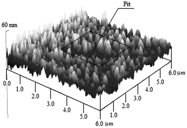
Atomic force microscopy topography scan surface of pre-CMP selective layer showing pit
The image in Fig. 1 is a 6×6 μm AFM topography scan area. One can see a pit formed in the same area, after ∼80 s of scanning/scratching over a 3×3 μm area in the middle of 6×6 μm area, with a load force ∼200 nN at pH 10. Depth of the pit depends on scanning/scratching time and slurry solution pH.
The removal mechanism in the selective layer CMP can be understood by studying the AFM topography, and by controlling the synergy between the mechanical wear and electrochemical interaction on the surface, good planarisation can be achieved. Therefore, the reasoning for better polishing can be seen as the synergy of the controlled oxidation and subsequent removal process of the oxide at the selective layer surface. In case of excessive mechanical wear or excessive corrosion action, surface polishing is poor.
Comparing the qualitative behaviour obtained for the removal rates as a function of pH with reported CMP data, 16, 17 one can see a definite correlation in Fig. 2. For the qualitative comparison, we put the same rates for the pH of 3. Quantative comparison reveals the following. Oxide removal with the AFM happens considerably faster than the CMP selective layer removal.
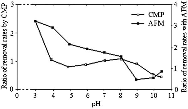
Comparison of CMP removal rates and AFM (rates for pH 3 taken to be same)
This confirms, essentially, a generally accepted model of copper CMP 16, 17 and brings the following model for the selective layer CMP: the originally corrugated/patterned selective layer surface is oxidised while immersed in the slurry solution.
A serious advantage of the AFM technique is its stability to measure all forces acting between the slurry particles and the polishing surfaces while polishing/scratching. Because it is plausible to expect direct correlation between the removal rate and the force of friction, between the AFM tip and surface, we measure the friction force. Such measurements were carried out on the selective layer surface treated as before, and then immersed in the aqueous solution of the corresponding pH. Higher friction areas were captured in 20–30 different points on the surface selective layer. 18 At each point, the higher areas were measured for a range of load forces.
To exclude a possible contribution of topology into the measuring lateral force, each point was chosen as a relatively flat area of at least 300×300 nm.
The calculated friction coefficient was averaged over those measurements and presented in Fig. 3. Friction coefficients were measured for 7–10 different load forces. Then, the friction coefficients were calculated as the averaged ratio of the friction force to the total vertical force, which include the load force and the force of adhesion.
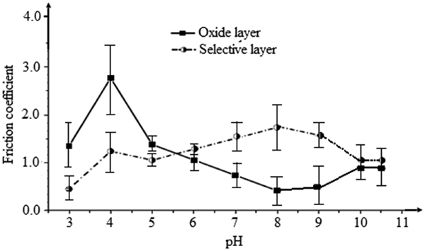
Dependence of friction coefficient on slurry pH for selective layer and oxide layer
Figure 3 shows dependence friction coefficient with the slurry pH. The error bars represent the root mean square (rms) of the calculated frictions coefficients. The values of the friction coefficient are somewhat higher than for a typical material. This may be explained by the measurements being carried out with the vertical force typical for scratching, i.e. wear. Wear usually leads to increase in friction forces. 18
As one sees from Fig. 3, the friction coefficient decreases as pH grows from 4 to 8 for the oxide layer, while in the selective layer it is only from 4 to 5 and from 8 to 10, which confirms the hypothesis that the removal rate directly correlates with the friction. However, the friction coefficient increases while the pH changes from 3 to 4 for oxide and selective layers respectively; for the selective layer, friction coefficient increases as pH grows from 5 to 8, and for the oxide layer, friction coefficient increases as pH grows from 8 to 10. After pH 10, there is a tendency to stabilise of the friction coefficient, both for the selective and oxide layers. This happens even though the removal rate seems to be higher for pH 3, as can be seen in Fig. 2. It is interesting to note that pH 3 is a special case.
As one can see from regular AFM topology images (see Fig. 1), the oxide is much rougher for the case of pH 3 versus the other considered pH x. Analysing removal noise by AFM, we can speculate that the oxide is being removed through grinding into nanosized particles of the oxide, which are noticeably smaller than in the case of the other pH x. These particles, sliding between the AFM tip and polishing surface, effectively lubricate the tip–surface contact and, consequently, decrease friction.
Figure 4 shows a 3×3 μm vertical deflection image of a selective layer surface in slurry (basic) solution (pH, ∼10), where a 600×600 nm region of the interior has been smoothed by 10 raster scans square at a nominal contact force of 200 nN.
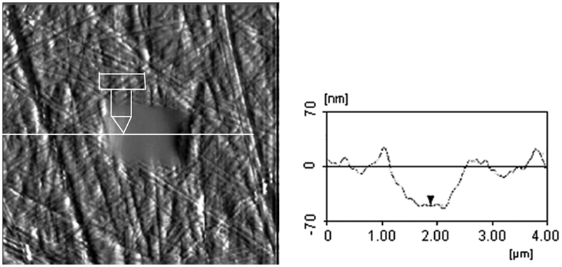
Vertical deflaction image of polished, selective layer surface (left) and its cross-section (right)
Deflection images often reveal small surface structures that are obscured in topographic images. The rms roughness of the diamond polished selective layer (outside the central smooth area) was typically 2·0±0·5 nm. Small area AFM scanning typically reduces the rms roughness of the surface to 0·26±0·1 nm, about twice the minimum surface roughness of this material due to its atomic structure. 13
During square raster scanning, the shape of the etch pit remains constant, while the shape of the AFM tip evolves constantly. After Ref. 19, under these conditions, thex area of the tip substrate contact is roughly proportional to time. As noted below, the friction and wear rates drop with time due to this increase in tip area.
Wear measurements during linear scanning are complicated by imagining issues. Since the width of the wear track is often comparable to the tip dimensions, wear track profiles can appear to be narrower than they really are.
During linear scanning, the area of tip–substrate contact depends critically on substrate wear, in addition to tip wear. Both wear rates were very approximate with the square root of the number of scans, but wear is much faster for linear scans.
Significantly, wear of linear scans is a linear function of force applied to the tip, while wear for square raster scans varies roughly with the square root of the number of scans for applied force. These results suggest that the local stress is controlled by tip wear during square raster scanning and by substrate wear during linear scanning.
Conclusion
Removal mechanisms in copper CMP in general and selective layer CMP in particular can be understood by studying the AFM topography. Good planarisation can be achieved by controlling the synergy between mechanical wear and electrochemical interaction on the surface.
Atomic force microscopy technique is ability to measure all forces (inclusive the force of friction) acting between the slurry and the polishing surfaces while polishing/scratching. Measurements based on friction in CMP can help to identify the interactions between the pad and different materials (with different friction coefficients) and surface topography as these are exposed and evolved during planarisation.
Atomic force microscopy technique was used to study the fundamentals of CMP of selective layer. Oxidation of the selctive layer surface was carried out in aqueous solutions of 5 wt-% of glycine at different pHs of 3–10·5. An AFM tip of radius of ∼50 nm was used to mimic a single abrasive silica particle of slurry.
During the AFM scanning, such a silica particle moves over the surface being polished with a load force of 20–30 nN, which is about the estimated force for a single abrasive particle during CMP. Such scanning removes the surface layer at different rates. This rate is lower for higher pH and for longer polishing times. The pH dependence of the observed removal rates is consistent with CMP results reported previously. The scan rate was 360 nm min−1, which has met the industry requirement (more than 300 nm min−1). The reported results were collected only for the cases when the tip wear was negligible.
Comparing the obtained AFM removal rates of the oxide layer with the CMP experimental rates, we conclude that the oxide removal happens cansiderably faster then the actual CMP selective layer removal.
This suggests a model for copper CMP, in which an originally corrugated selective layer surface is polished by fast oxide removal from the tops of the oxidised selective layer surface by the abrasive particles stuck to the polishing pad. The exposed top selective layer areas oxidised further and scratched away by the abrasive again. This process repeats itself until no tops on the selective layer surface remain, i.e. planarisation is complete.
Atomic force microscopy allows one to examine the effects of applying highly localised stress to a surface, and in the presence of slurry solutions, wear can be investigated; wear what appears during linear and square scans, and they depend on the number of scans.
Atomic force microscopy technique was also used to monitor forces acting between the slurry particle and surface while being polished. The friction forces acting between the AFM tip and surface being polished were measured. With the exception of pH 3, the smaller friction coefficient corresponds to a slower removal rate. However, quantitatively, the friction removal rate dependence is highly non-linear.