
Abstract
Plasma sprayed molybdenum coatings with different coating thicknesses (100, 200, 300 and 400 μm) were deposited on steel substrate. The variation in microstructural characteristics and properties of coatings with various thicknesses was investigated. The microhardness was measured using a Vickers’ indenter. The quantitative investigation of porosity is carried out with the help of computerised image analyser. The influence of coating thickness on wear resistance was estimated using pin on disc wear test rig. The worn surface of coated pin was characterised by scanning electron microscopy. The experimental results indicated that porosity of coating was increased with increased coating thickness. The enhanced coating thickness also resulted in decreasing microhardness and reduced wear resistance. In this study, the plasma sprayed thin coating with thickness of 100 μm possesses the lowest porosity, the highest hardness and better wear resistance.
Introduction
Thermal sprayed coatings offer cost effective alternative to modify the component surface properties. These are used in a wide range of industrial applications, primarily for wear resistance, thermal barrier and corrosive resistance.1–4 Plasma spraying technique, among the various thermal spraying techniques, has attracted particular attention for its extremely high processing temperature. In this technique, the material is heated to a temperature ∼10 000°C and the microstructure is formed, when individual, fully or partially molten particles, travelling at a particular velocity, flatten, adhere and solidify on impact with the substrate material.5,6 The quality of the coating depends on its structure, phase composition and uniformity of the microstructure. 4
The plasma spray technique produces a heterogeneous layered structure of thermal sprayed coatings consisting of interlamella or volumetric pores and weak interface between splats. 7 Owing to the high velocity and temperature gradients in the plume, the small changes in the parameters can cause momentous changes in the particle properties and thus change the microstructure features. Among these features, porosity level is a key parameter describing the anisotropy of sprayed coatings and controlling their properties.4,8 Kesler et al. 9 reported that enhanced thickness will increase the amount of residual stress and thus affect the final properties of coating. Yin et al. 10 investigated the influence of thickness parameter on porosity, hardness, surface roughness and corrosion resistance of the coatings. They reported that the porosity of plasma sprayed coating was increased with increasing thickness, which in turn resulted in the decrease in microhardness. Sarikaya 11 has investigated the effect of spraying distance, substrate temperature, coating thickness and surface roughness on the properties of the sprayed coating. He found that the increase in coating thickness lowered the hardness and enhanced the porosity.
Holmberg et al. 12 analysed the material deformation and the influence of coating thickness and elastic modulus by three-dimensional finite element method. They concluded that the thicker coating has higher stress concentration compared to the thin coatings. Higher stress concentration in coating leads to the formation of cracks, delamination and surface failure. Wang et al. 13 discussed the effect of coating thickness on the wear particle generation. They found that wear particle generation generally increases with increasing the coating thickness.
In view of the above, the molybdenum coatings, as an example of thermal sprayed deposits, were plasma sprayed with different thicknesses onto steel substrate, and the intrinsic correlation between coating thickness parameter and porosity, hardness and wear resistance of coating was explored.
Experimental
Materials
Materials used in the present investigation are commercially available Mo powder with a particle size that varies from 15 to 40 μm. The substrate material used for the coating was AISI 1020 steel, since this material is extensively used for a variety of general engineering and construction applications such as pins, chains, shafts, hard wearing surfaces, axles and automobile parts. The AISI 1020 steel was prepared as pin with 10 mm diameter and 30 mm height.
Plasma spraying
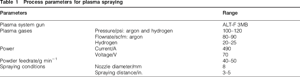
Mo coatings in thicknesses of 100, 200, 300 and 400 μm were deposited on AISI 1020 steel by atmosphere plasma spraying technique (ALT-F 3MB). The plasma gas consists of 25 vol.-% argon, and 25 vol.-% hydrogen was used. The coating feedstock material was injected vertically into the plasma jet by argon carrier gas for primary flow and hydrogen for secondary flow. The plasma spraying was performed with a parameter combination shown in Table 1. Before spraying, the substrate surface was grit blasted to improve adherence.
Process parameters for plasma spraying
Characterisation of coatings
The porosity of plasma sprayed coating was measured using computer image analyser. Four to five fields were selected for the measurement of values of porosity. The microhardness of Mo coatings was measured using a microhardness tester at a load of 0·1 N. The microstructure and worn surface morphologies of the coatings were analysed using a scanning electron microscope.
Experimentation
The plasma sprayed samples were tested for its dry sliding wear characteristics using pin on disc test rig as per ASTM G99 standards. The dry sliding wear test rig is used to assess the wear behaviour as shown in Fig. 1. The initial mass of the specimen is measured in a single pan electronic weighing machine with an accuracy of 0·0001 g. Wear tests were carried out by sliding the coated pin against the EN32 steel disc of hardness 62 HRC, under dry conditions by varying the applied load, sliding speed and sliding distance. After the test, the specimen is cleaned with acetone to remove any debris and then dried, and the final mass of the specimen is measured. The difference between initial mass and final mass is wear weight loss. This mass loss is converted into wear volume loss using the density. The wear resistance of the coatings is studied as a function of the applied load, sliding speed and sliding distance.
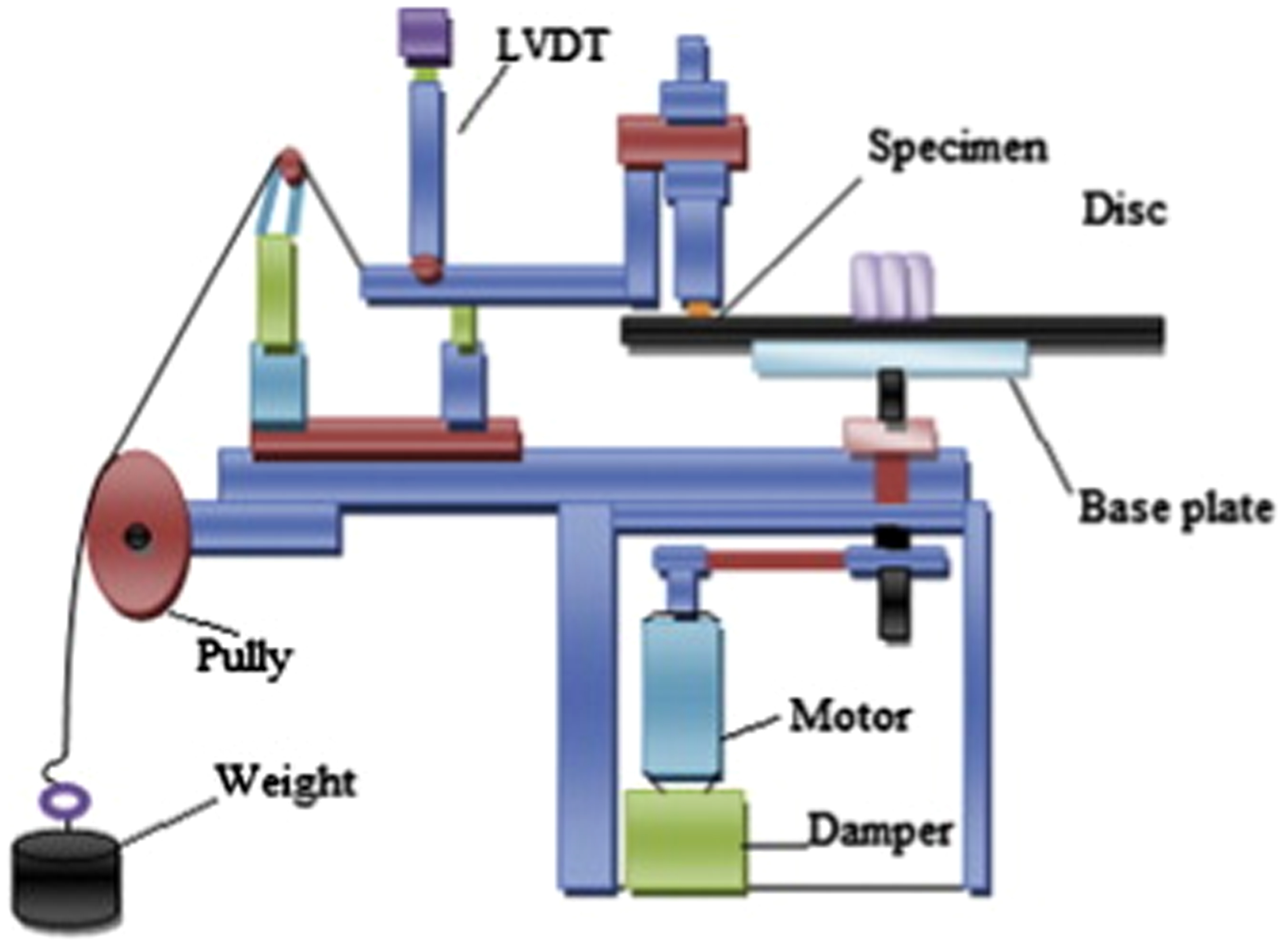
Dry sliding wear test rig
Results and discussion
Results
Figure 2 illustrates the variation of porosity as a function of the coating thickness. The porosity of plasma sprayed Mo coating almost uniformly increases up to 300 μm coating thickness. The degree of increase in porosity from 100 to 200 μm and 200 to 300 μm is 24 and 23% respectively. However, a substantial increase in porosity ∼40% occurs between 300 to 400 μm coating thickness. The porosity of plasma sprayed Mo coating varies from 6·17 to 17·64% and showed an increasing trend with elevated thickness.
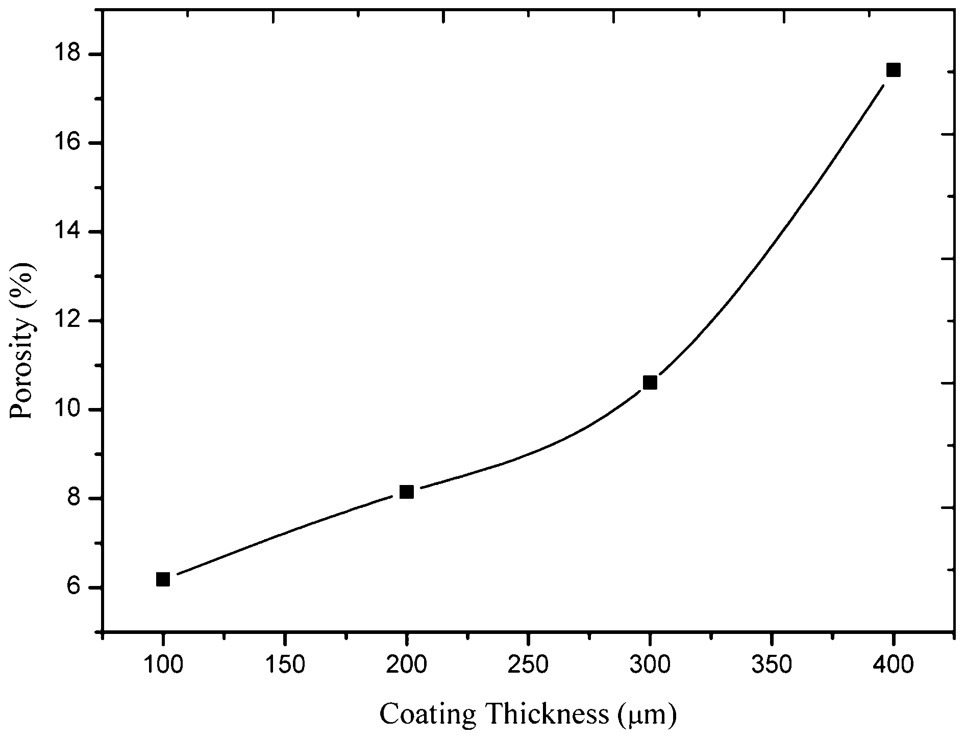
Variation of porosity as function of coating thickness
Figure 3 depicts microhardness of plasma sprayed Mo coating for varying coating thickness. The microhardness of plasma sprayed Mo coatings decreases as the coating thickness increases. The microhardness of 100 μm coating is 773 HV0·1. In the case of 200 and 300 μm, there is not much considerable amount of decrease in microhardness as the coating thickness increases. Above 300–400 μm, there is a substantial decrease in the microhardness.
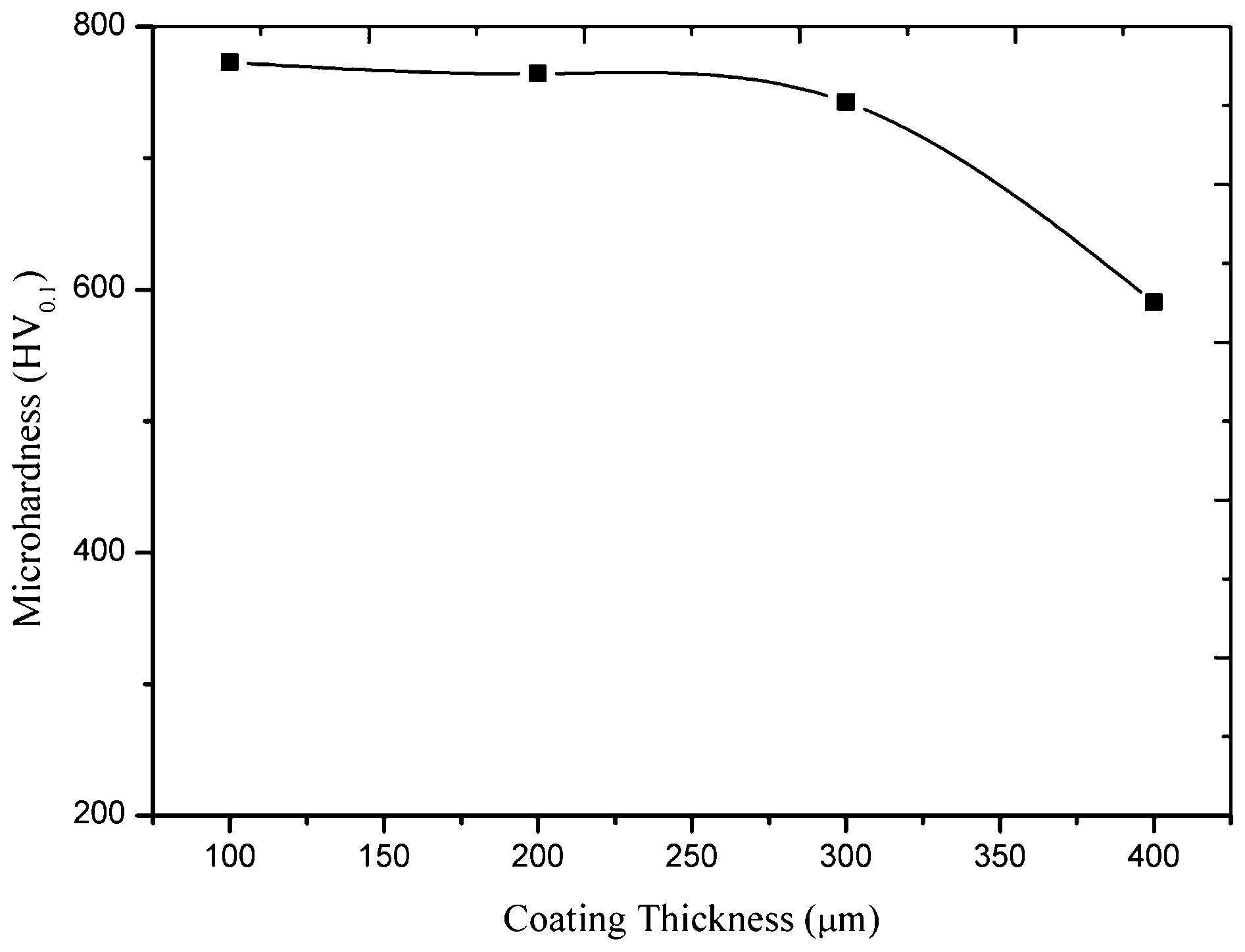
Variation of microhardness as function of coating thickness
Figure 4 depicts the volume loss of Mo coated AISI 1020 steel for varying applied load at a constant sliding speed of 2·8 m s−1 and sliding distance of 5000 m for different coating thicknesses. It is observed that as the applied load increases, the volume loss also increases for all the different coating thicknesses. Similar results were observed by Hwang et al. 14 and Uyulgan et al. 15 The 400 μm coating thickness has more volume loss as compared to other coating thickness irrespective of applied load. The 100 μm coating thickness shows a better wear resistance as compared to other coating thickness specimens.
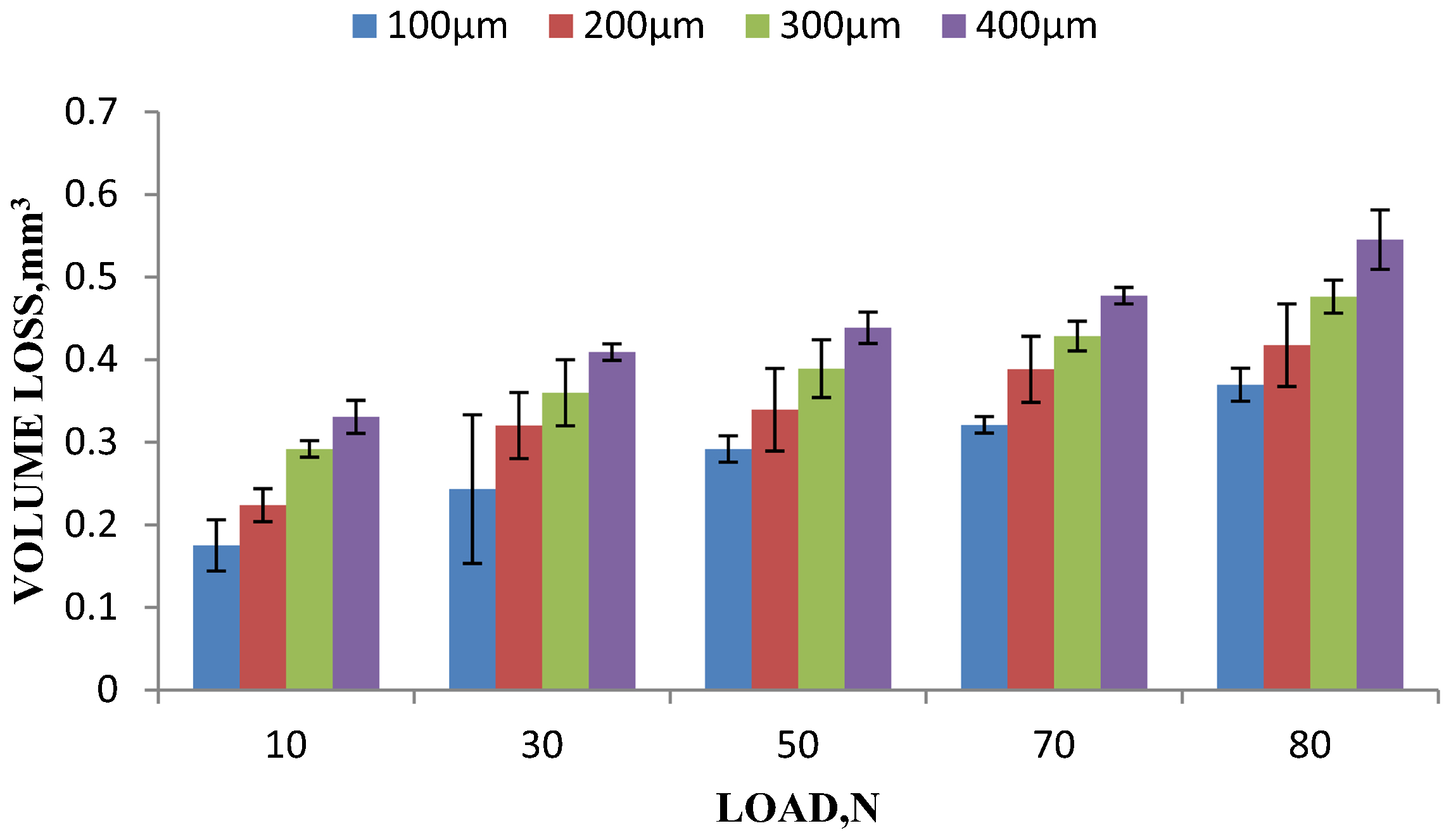
Variation of volume loss as function of load
Discussion
The results of porosity (Fig. 2) show that as the thickness of the coating increases, the porosity increases. In plasma sprayed coating, the porosity is originated due to entrapped gas and thermal shrinkage of splats. The amount of entrapped gas and thermal shrinkage will increase as the coating thickness increases and causes for increased porosity. The porosity is extensively considered as the main cause to the low hardness and wear performance as compared to dense and sintered materials.16–18
The results of microhardness (Fig. 3) illustrate that as the thickness of coating increases, the microhardness decreases. This is due to increase in porosity. Venkataraman et al. 19 and Rico et al. 20 also reported that increase in the porosity will lead to the decrease in coating hardness. Another reason for decrease in microhardness is due to change in lamella cooling rate. Owing to the change in lamella cooling rate, the cooling rate for thinner coating is high; therefore, it produces finer microstructure. For thicker coating, the cooling rate is low; therefore, it produces coarse microstructure. Generally, the finer microstructure of coating has higher hardness values as compared to coarse microstructure. Moreau et al. 21 also agreed that the cooling rate will change as the coating thickness increases and change in lamella cooling rate affects the microstructure of the coating.
It is observed from Fig. 4 that because of the increase in coating thickness, the volume loss is increased gradually irrespective of the applied load. It has been observed that the porosity of sprayed coating increases as coating thickness increases and microhardness of the sprayed coating decreases. These results also agreed with Yin et al. 10 The thicker sprayed Mo coating has more volume loss due to lower hardness values as compared to thin sprayed Mo coatings; this is confirmed by Stolarski and Tobe. 22
The thicker coatings consist of more pores, lower microhardness and higher stress concentration. This leads to formation of cracks, delamination and fracture of the coating surface. 12 The lesser wear volume loss was observed in thin coatings, since they are less porous and have higher hardness values.
Increase in the applied load leads to increased wear volume loss of plasma sprayed Mo coating for different coating thicknesses. This is due to harder brittle Mo splats. Hence, interfaces between splats can be easily separated or some splats are fractured; such phenomena of fracture and delamination vary with wear load and considerably affect the wear rate. The fracture and delamination become more severe as the applied load increases. The acceleration in wear rate leads to the transition of wear mechanisms.14,23–25
Figure 5a illustrates an SEM image of the worn coating surfaces at 30 N load for 100 μm coating thickness. The worn surface reveals distinctive abrasive wear mode in which grooves are formed along the wear direction and small microcracks are found, which are responsible for wear volume loss. The intensity of grooves is less as compared to other coating thickness. Figure 5b shows the worn surface of the coating at 30 N load for 200 μm coating thickness. The worn surface shows the formation of noticeable microcracks and grooves on the coating surface as compared to 100 μm coating thickness. Figure 5c depicts the worn surface of the coating at 30 N load for 300 μm coating thickness. The worn surface demonstrates the formation of noticeable microcracks, which are responsible for delamination of the coating surface. The degree of delamination is higher as compared to 100 and 200 μm coating thickness. Figure 5d represents the worn surface of coating at 30 N applied load for 400 μm coating thickness. The worn coating surface exhibits distinct microcracks, grooves and delamination as compared to other coating thickness.
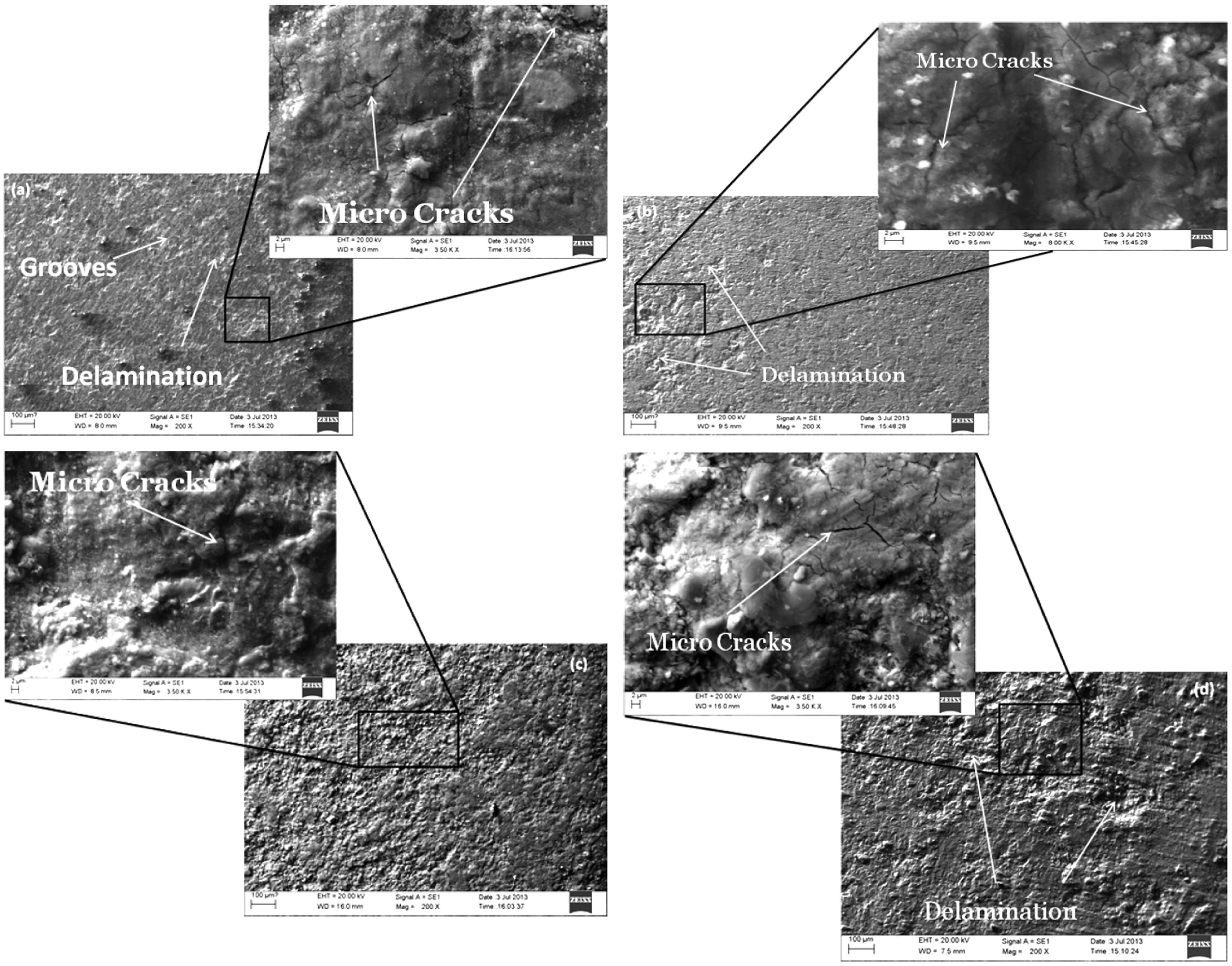
Images (SEM) of worn surface at 30 N load for a 100 μm, b 200 μm, c 300 μm and d 400 μm coating thickness
From Fig. 5, the depth of groove and magnitude of delamination increase as the coating thickness increases, since the hardness of coating is a function of wear resistance. In the magnified image, it is observed that the formation of microcracks in all the coatings and microcracks was more distinct in the higher coating thickness. This is because the higher coating thickness has higher porosity and low microhardness values. The low microhardness and high porosity in the coating result in higher wear volume loss.11,19,20,25 Therefore, the wear volume loss increases as the coating thickness increases.
The lower porosity, higher hardness and lower wear volume loss can be obtained at lower coating thickness, i.e. 100 μm. If there is a continuous wear of the coated surface, it is usual to have a coating that is as thick as possible to allow wear without being penetrated so that bulk material is exposed. Thus, the selection of the right thickness of the coating is always a trade off between a wear margin and resistance to fracture. Therefore, in the present study, 300 μm is noticed as the right coating thickness since substantial increase in porosity and decreased microhardness occurs >300 μm coating thickness.
Conclusion
The wear behaviour of plasma sprayed Mo coatings of different coating thicknesses was studied. The influence of coating thickness parameter on porosity, hardness and wear resistance of coatings was investigated. The following conclusions were drawn from the present study.
The porosity of plasma sprayed Mo coating was increased with increasing coating thickness. The increase in porosity resulted in the decrease in microhardness of the sprayed Mo coating. The substantial increase in porosity and decrease in microhardness were observed after 300 μm coating thickness.
The wear results indicated that the volume loss increased with increasing coating thickness. The volume loss in sprayed Mo coating occurs mainly due to the formation of grooves, cracks and delamination. The thin plasma sprayed Mo coating shows the better wear resistance as compared to the thicker plasma sprayed Mo coating.
The coating must be as thick as possible to allow wear without exposing the bulk material. Thus, the choice of right thickness of the coating is always a compromise between a wear margin and resistance to fracture. Therefore, in the present study, 300 μm is noticed as the right coating thickness since substantial increase in porosity and decreased microhardness occurs >300 μm coating thickness.