
Abstract
WC-Fe composite coatings were prepared on IC45/080A47 steel substrates by argon arc cladding technique. Minute amounts of La were added into the coating, and the microstructure was investigated to find the relation to rare earth. Results show that RE does not change the categories of phases, and the main components remain α-Fe, Fe3W3C, WC and W2C. However, the distribution of carbide particles is optimised. It reduces the agglomeration and bridging in the cladding layer's structure, makes the particles distribute homogeneously and restrains the dissolution of WC and the formation of fishbone shaped dendritic carbides. It promotes the formation of granular carbide and refines grains. It also reserves the WC particles in the composite coating and improves the average hardness and wear resistance.
Abrasion of engineering materials mostly starts from the surface. Therefore, material surface protection has an important value in engineering application. 1 In a large amount of engineering technologies, adding a proper amount of rare earth elements on the coating may produce a great modification effect, such as improving the surface hardness, wear resistance, fatigue strength, fracture toughness, bonding strength between modified layer and matrix, high temperature oxidation resistance, corrosion resistance and other properties of components.2–6 As rare earth elements, cerium and lanthanum have been successfully applied to many fields, such as metallurgy,7–8 chemical industry, etc., because of the significant effect on refining, purifying and structure improving for steels and its composite materials.
A lot of researches have been performed for the characteristics of particle phase structures in composite coating and the effects of adding RE. Dubourg et al. found that the bulk particle phases (50 to 150 μm) were brittle. 9 After spalling, abrasion would be accelerated. Hans and Birgit pointed out that agglomerated particle phases were easy to break in friction and would accelerate abrasion. 10 Chen and Wang found that, 11 in the composite coating, the particle phases transforming into dendrites would lead to a more violent fluctuation of the friction coefficient. Therefore, the characteristics of particle phases in the composite coating influence the hardness and wear resistance of the coatings. In addition, rare earth compounds La2O3 with hexagonal layered structure have a lubricating effect, which may reduce the coefficient of friction and improve wear resistance. 12 Liu et al. found that in the RE laser alloying test on cast iron surface, the dilution of carbon was reduced effectively in the melting area. The eutectic degree was increased. The hardness of the surface was up to 1000HV0.2. The wear resistance was 3.18 times higher than that of cast pearlite. 13 Su et al. found that, by adding RE, the microstructures of the coating material were refined, and the grain boundaries were strengthened. Thus, the hardness, wear resistance and corrosion resistance of material were improved. 14 This paper attempts to investigate the effect of rare earth element on the microstructure, especially the state of carbide in argon arc cladding WC reinforced iron matrix composite coating by adding a small amount of La2O3.
Experimental
Materials
Experimental substrates are IC45/080A47 steels with the size of 100 × 25 × 10 mm. The morphology WC powders with 30 to 40 μm size and La2O3 ball milled powders at 99.9% purity is shown in Fig. 1. The rare earth oxide powders and WC powders were mixed in a ball mill for 3 h and then dried. The adding amount of rare earth is 0.2 wt-%. The WC particles were broken into finer particles in the milling process for its great brittleness, and the maximum particle size is 15 μm.
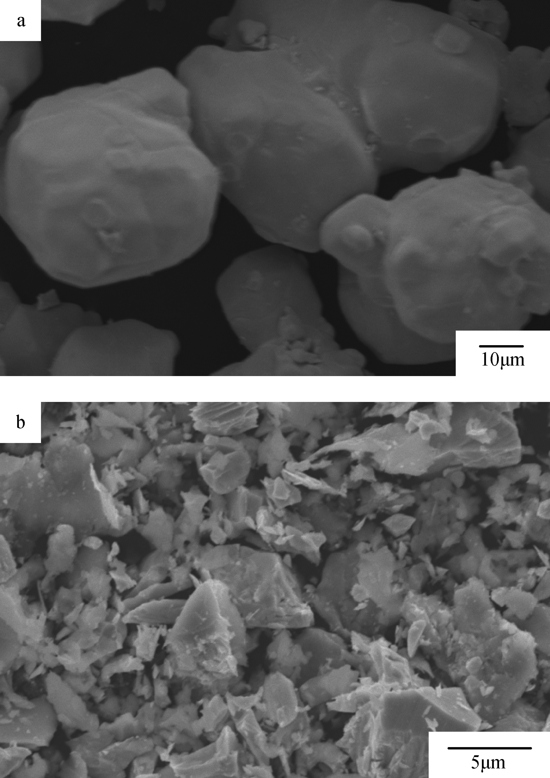
Morphology of a WC particles without milling and b WC-La2O3 powers after ball milling
Preparation of coating
Before coating, oil and rust removal and polishing were necessary for the matrix. When the fresh metal was exposed, the homemade organic binder was used to bond the powder for coating into a paste, and the treated specimens were precoated with the powder. The coating thickness was ∼0.2 mm. The coated specimens were placed in a ventilated area to dry, so that the water inside can be sufficiently volatilised. After that, they were placed in a thermotank at 30°C for 2 h. For the present experiment, argon arc cladding was used to heat and melt, the tungsten electrode was adopted and 99.9% argon was used as shielding gas. In this study, the electric current was 70 A, the voltage was 20 V, the mobile speed of welding gun was 120 mm min− 1, and the gas flow was 10 L min− 1. In order to ensure a more stable arc, high melting efficiency, deep and narrow melt layer, small workpiece shrinkage stress and strain, the DCSP was used, and the pass overlap rate ranged from 40 to 50%. In order to avoid cracks caused by excessive cooling rate of the cladding layer, the samples were put in a thermotank at 200°C and cooled slowly to room temperature after cladding.
Analytical methods
The samples were cut by wire cutting and corroded with 9 vol.-% nitric acid ethanol solution. The microstructure at the attachment region of the cross-section and the surface morphology of samples were observed by a Card Zeiss EvoMA15 type SEM. Phases were analysed by X-ray diffraction (XRD) (Cu Kα ray source, D/MAX2500VL/PC type). Chemical composition of microarea and element distribution in coating were determined by Oxford INSTRVMENT energy dispersive spectroscopy (EDS).
Results and analyses
Phases analysis of composite coating
Fig. 2 shows the XRD patterns of composite coating with/without rare earth element. The calibration results show that the major component phases are α-Fe, Fe3W3C, WC and W2C. Since the RE contents are low, there is no peak of rare earth compounds, although the relation intensity of diffraction peaks of different phases changes. It indicates that rare earth has no significant effect on the structure of the coating phases.
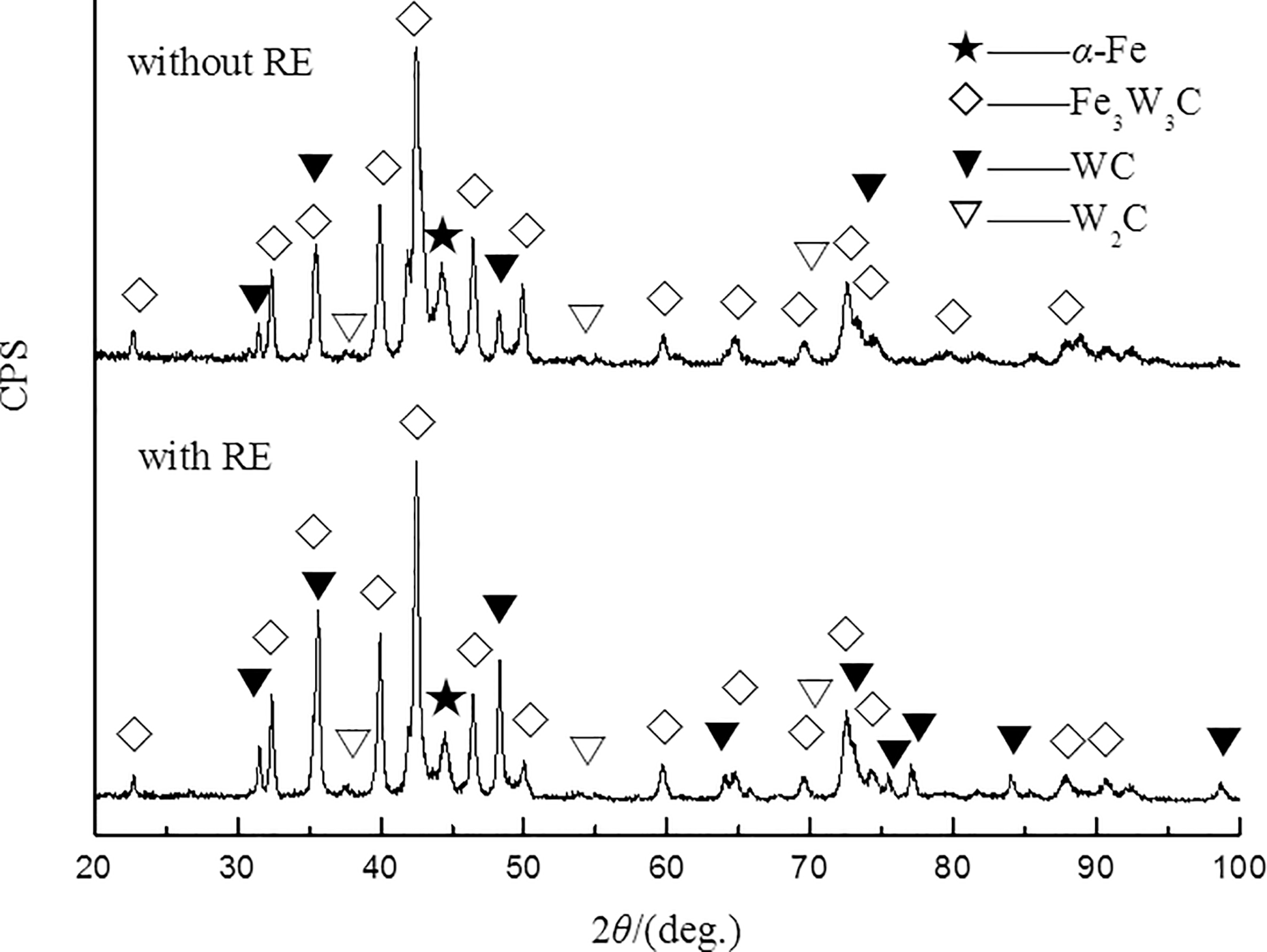
X-ray diffraction spectrum of composite coating
Effect of rare earth on characteristics of composite coating section
Fig. 3 shows the backscattered section structure of matrix and argon arc cladding layer with/without rare earth element. As can be seen from the figure, the coating and the matrix have good bonding, no obvious crack, porosity, inclusion and other defects. In Fig. 3, the coating without rare earth bonds to the substrate in a straighter combined line with ∼5 μm thick plane crystals in the bonding layer. The coating with rare earth has ∼3 μm thick plane crystals and uneven combined line. It has larger combined area and combines closer than the former. A columnar crystal occurs nearby the plane crystals in the coating without rare earth, but the alloy with rare earth contains almost no columnar dendrite. Therefore, adding rare earth can inhibit the formation of columnar crystals. As shown in Fig. 3, there is no particle in the region near the substrate without rare earth, but there are many white dispersed particles in the cladding layer with rare earth.
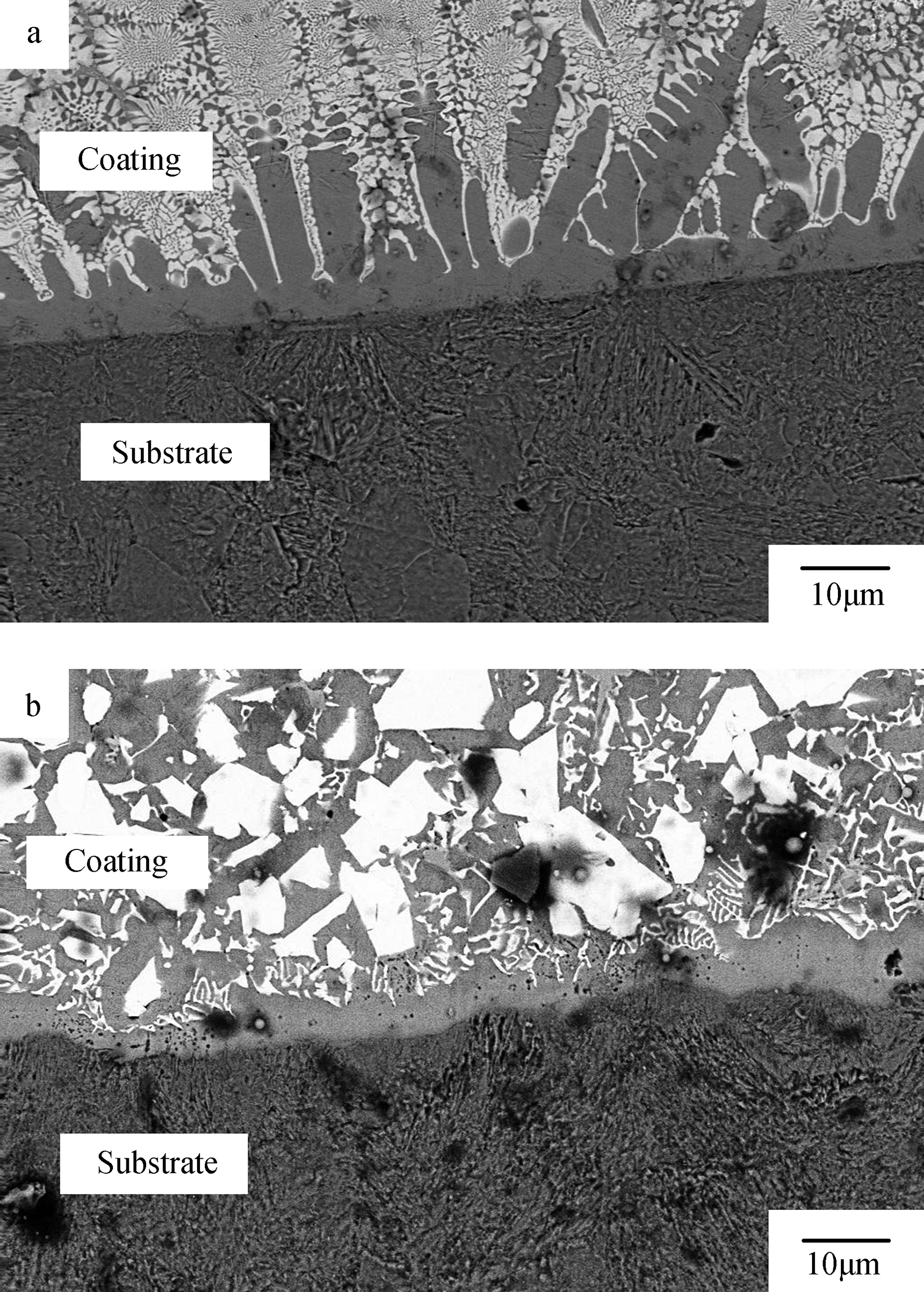
Microstructure of interface: a without RE; b with RE
Effect of rare earth on structure characteristics of near surface region of cladding layer
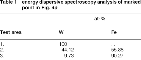
Fig. 4 shows the SEM photos of the near surface phases in the cladding layer with and without rare earth. It can be seen that, in the matrix near the cladding layer's surface without rare earth, the particles are broken, congregated, obviously bridging and in different size. However, the introduction of rare earth makes the particles distribute uniformly, and to be fine, particle segregation and bridge phenomenon decrease, and no obvious pore and crack exist in the coating. These are beneficial for restraining the formation and propagation of cracks as well as improving the performance of the alloy. The EDS analyses of the near surface structure of cladding layer in Fig. 4a are shown in Table 1. Along with the XRD (Fig. 2), the massive particles at place 1 are WC, the fishbone shaped phase at place 2 may be alloyed cementite Fe3W3C and the grey phase at place 3 is matrix structure of cladding layer with a small amount of W solved in it. The coating near surface in Fig. 4b is mainly formed by dispersed massive particles, a little thin rod phase and grey cladding matrix. Its map scanning results are shown in Fig. 5.
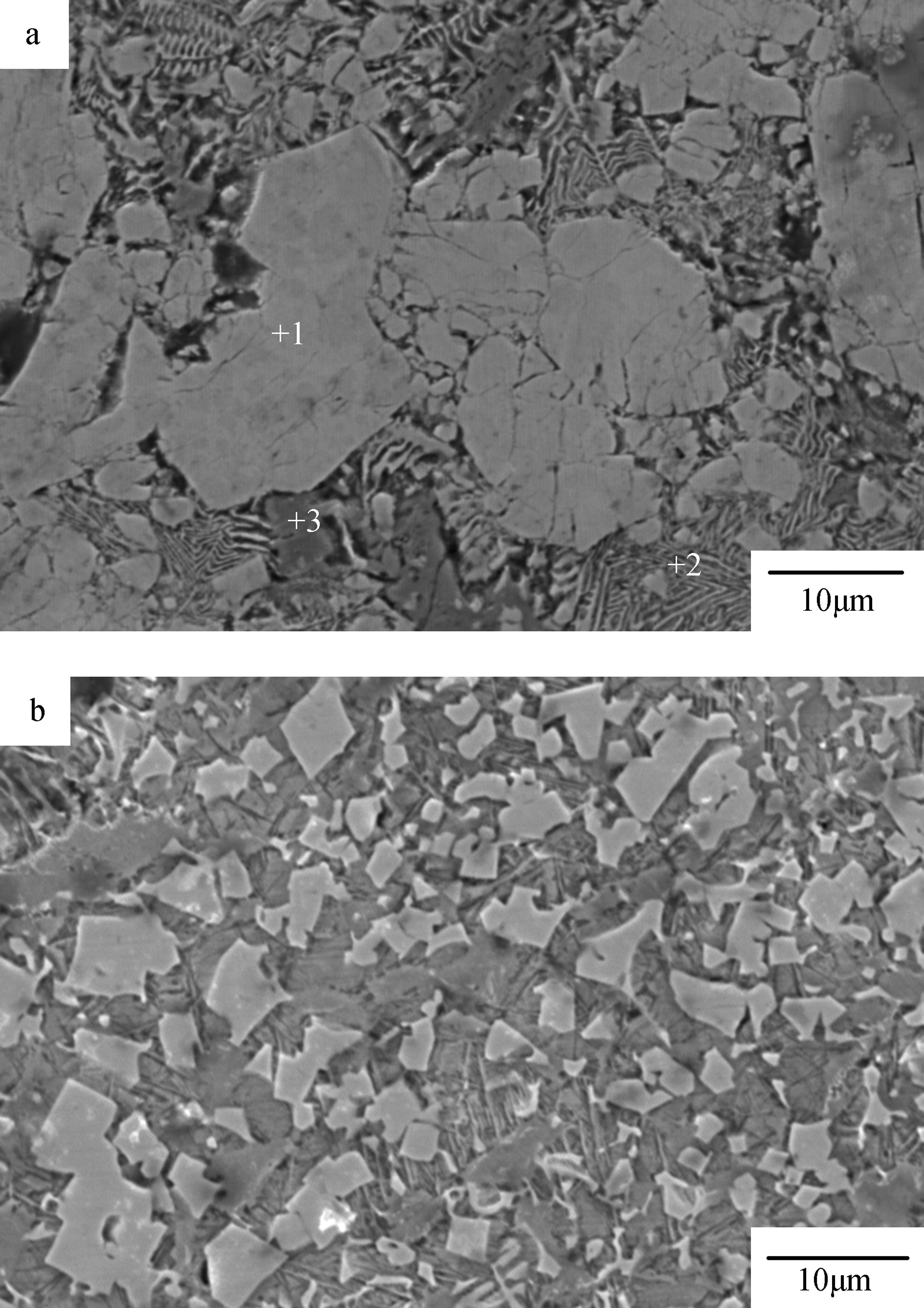
Microstructure of surface and EDS points: a without RE; b with RE
energy dispersive spectroscopy analysis of marked point in Fig. 4a
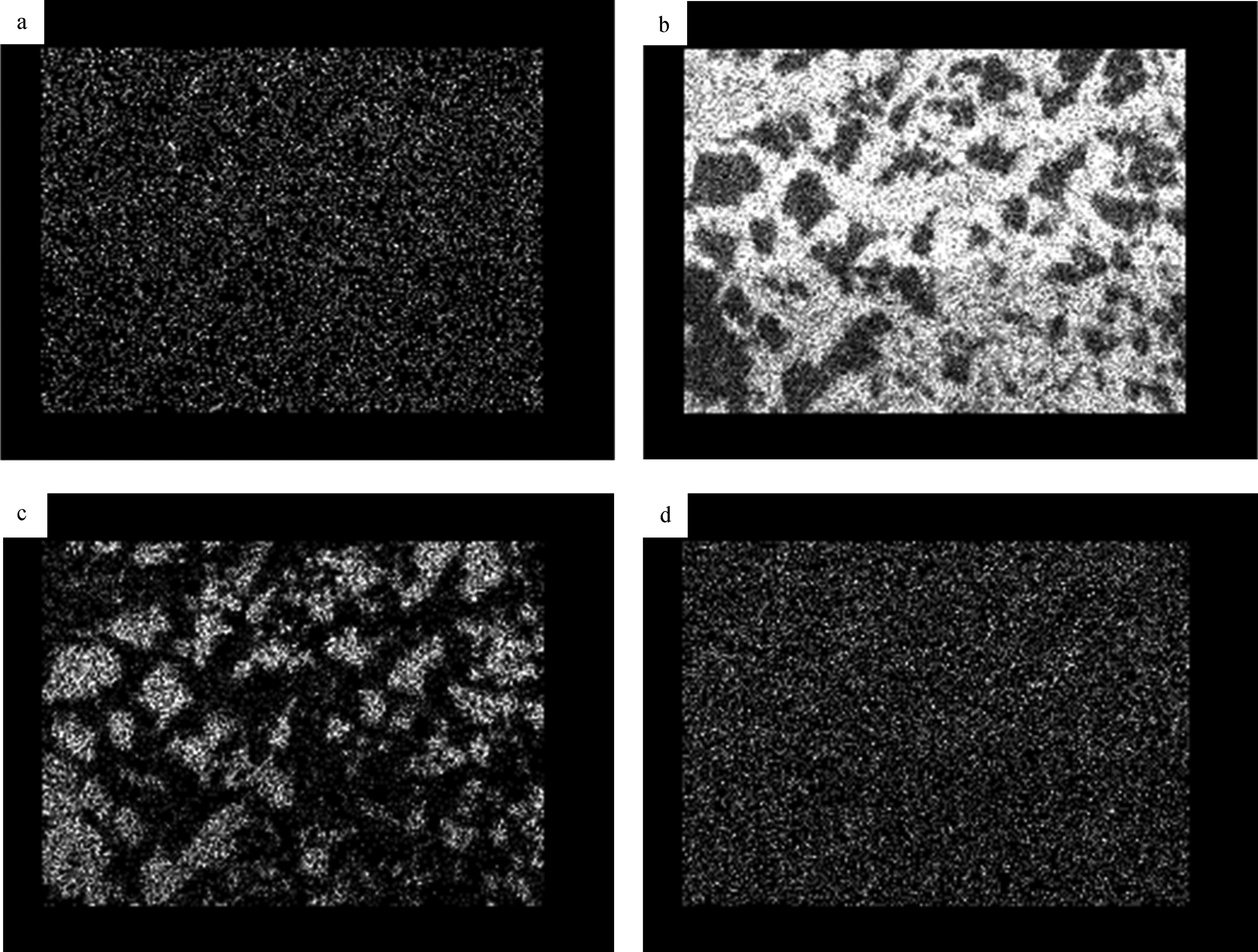
Surface element: a C, b Fe, c W and d La distribution of coating
It can be seen from the map scanning results (Fig. 5) of the composited cladding layer with RE that the concentration distribution of each element has obvious regional characteristic. Since the ability to accept excited characteristic electron from the spectrometer of EDS is affected by the morphology, the distribution of each element has a certain relationship with the structure of the cladding layer. Although there exist some background signal, the concentration distribution of elements is still significant. In Fig. 4b, W is mainly distributed in white massive phase, and the Fe element is mainly distributed in the matrix and the edge of the massive phase. It can be judged by the EDS results, the XRD, the microhardness (1700HV0.2) and the morphology of white massive that the large particles in composited cladding layer with RE are original WC particles, and the small particles may be the partial dissolved original WC or recrystallised W2C and in situ crystallised WC particles. Therefore, adding rare earth elements has a significant effect on the microstructure of the composited cladding layer.
Morphology of WC particles and surrounding organisation in middle of cladding layer
Fig. 6a shows the characteristics of WC particles in the cladding layer without RE. It can be seen that the diameter of the WC particle is ∼20 μm, and a lot small fishbone shaped eutectic structures exist around the WC particles. These phases are all due to the dissolution of WC particles. Figure 6b shows the characteristics of WC particles in the cladding layer with RE. The WC particle is ∼15 μm in diameter and smooth, and it has no flaws on the surface. However, there are numerous small uniformly distributed particles around the WC particles, without fishbone shaped eutectic structure. From the comparison chart in Fig. 6, we can see a big obvious difference in the morphology of the structure surrounding the WC particles. There exist a lot of fishbone shaped eutectic structures in the coating without RE, but only particles with RE. It shows that adding RE can prevent the formation of fishbone shaped eutectic structure and promote the precipitation of small uniform particles.
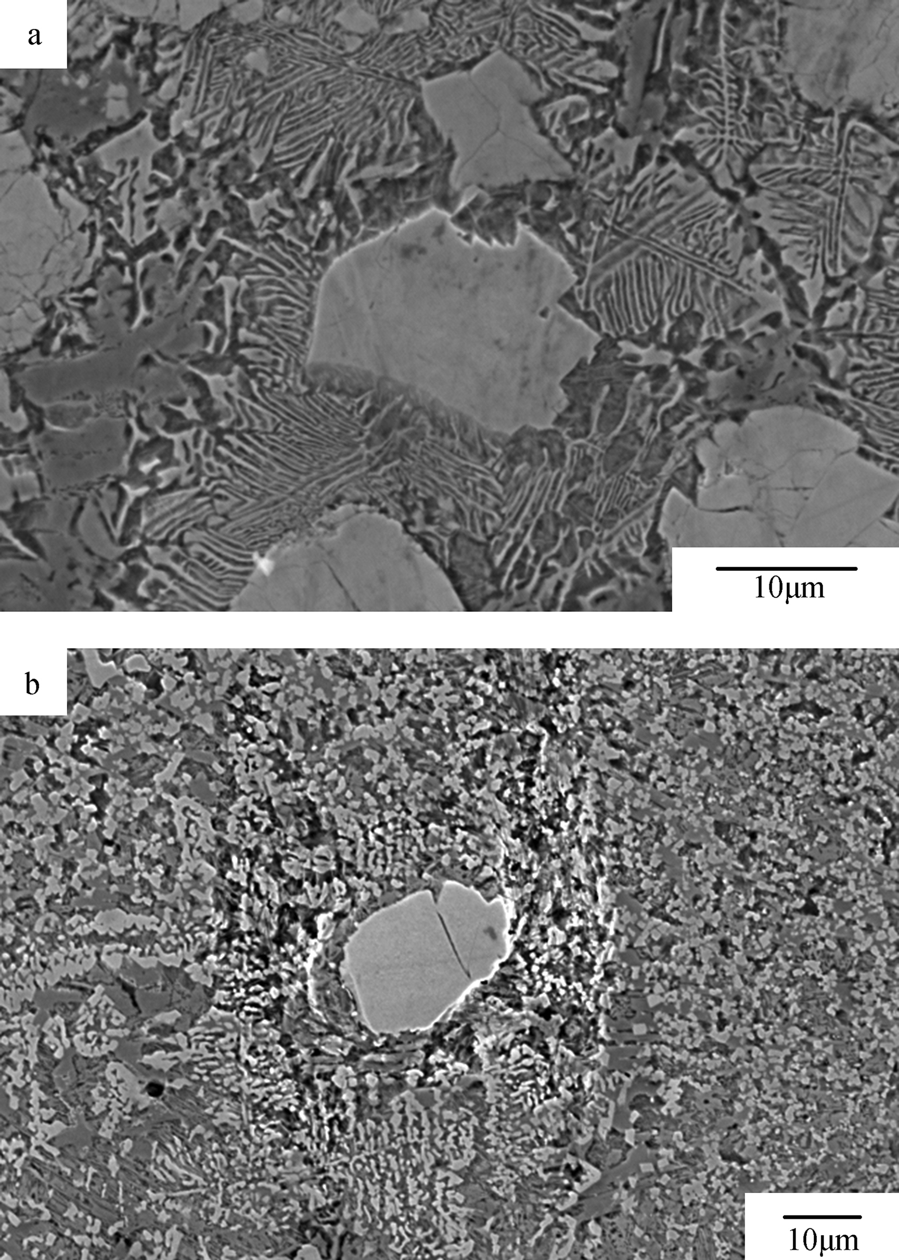
Characteristics of typical carbide in cladding layer: a without RE; b with RE
Effect of rare earth on dissolution behaviour of WC particles
In this cladding process, the compositions of the matrix surrounding the WC particles are changed. Obviously, it is due to the dissolution of WC under certain conditions, subsequent migration of W in the matrix and migration of elements like Fe in the opposite direction. Figure 7 shows the dissolution of WC particles before and after adding RE. From Fig. 7a and b, there are obvious dissolutions of boundary of WC grains before adding RE and ∼13 μm thick transition around WC particles. The particles get round obviously. The contents of W, Fe are different from the matrix and WC particles. However, the gradients are relatively smooth. After adding rare earth, as shown in Fig. 7c and d, there has no clear transition layer at the boundary of WC grains, which indicates that adding RE can effectively inhibit the dissolution of WC.
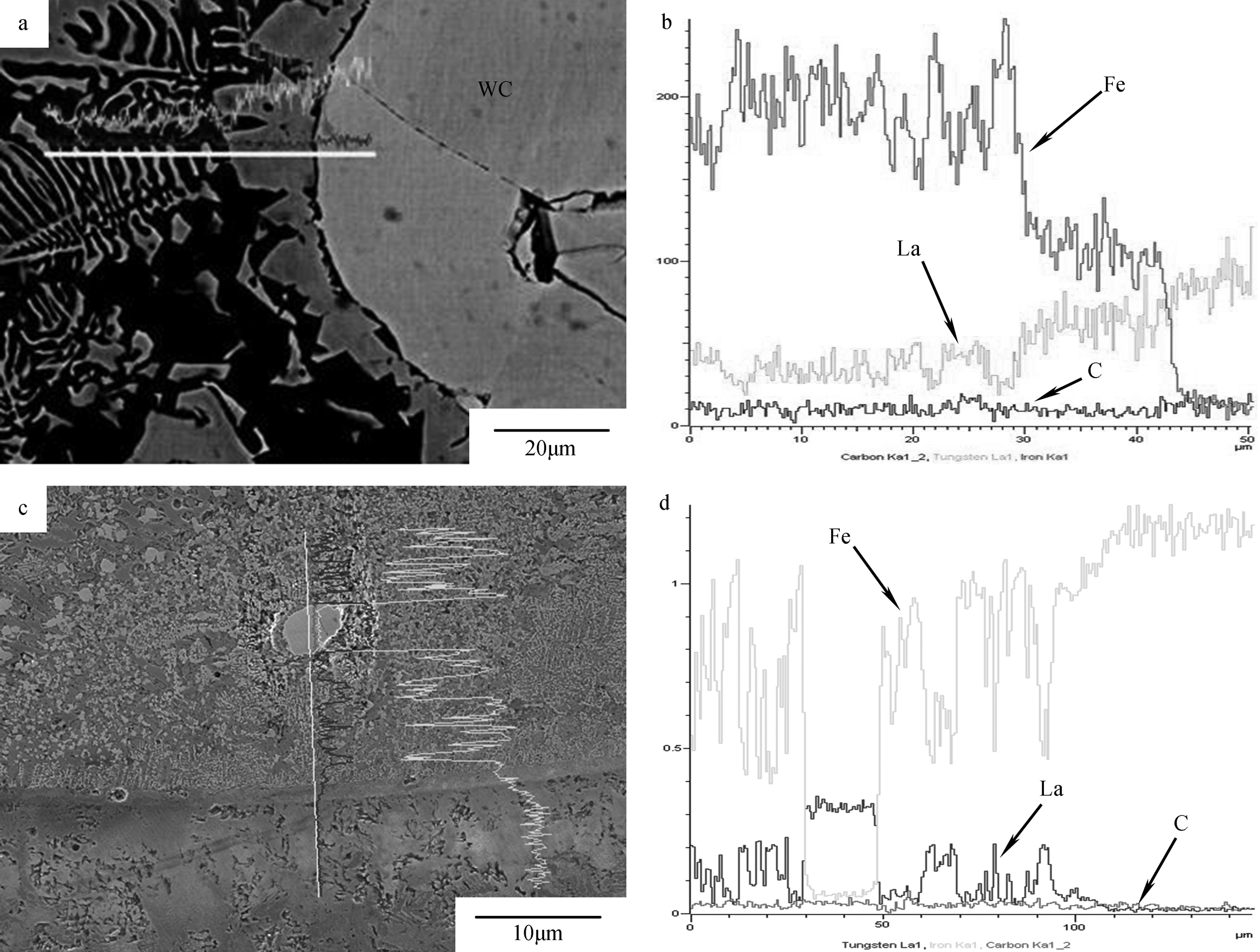
Interface reaction area of WC particles a without RE and c with RE: linescan result of corresponding elements b without RE and d with RE
Effect of rare earth on hardness of cross-section of cladding layer
Fig. 8a shows the distribution curve of the microhardness of the cross-section of the cladding layer without RE. From it, the microhardness of the near surface region is higher than other places. The average hardness of the cladding layer is ∼850HV0.2, which is much higher than that of the transition region (350HV0.2) or the matrix (210HV0.2), and the number is 4.5 times that of IC45/080A47 steel. The greater volatility of hardness of the cladding layer is due to the complex structure (original WC particles, primary crystals and eutectic structure) distributed in the matrix and the extent of the cladding layer diluted by matrix. The extent of the cladding layer diluted by the matrix increases gradually with increasing distance from the upper cladding layer, which leads to the decreasing of distribution of alloying elements and the weakening of the strengthening effect. The high hardness of the cladding layer is determined by the solid solution strengthening effect of alloying elements such as W and C, and at the same time, the formation of a large amount of M6C strengthening phases also has an effect of pinning strengthening on the matrix of the cladding layer.
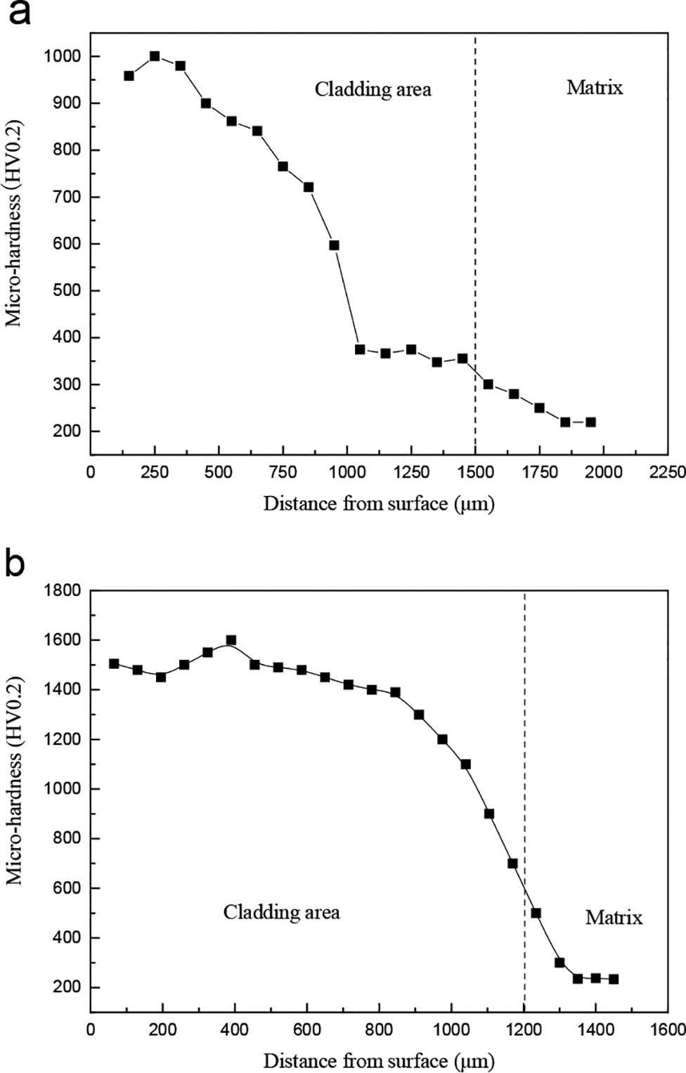
Distribution curve of microhardness of cross-section of cladding layer: a without RE; b with RE
Fig. 8b shows the distribution curve of the microhardness of the cross-section of the cladding layer with RE. The figure shows that with the distance from the surface increasing, the hardness remains at a high level (1500HV0.2). Then, the hardness decreases significantly and reaches the level of matrix (210HV0.2) soon. The stable distribution of hardness profits from the particle strengthening of WC and the dispersion strengthening of fine particles crystallised. Because of adding RE, the matrix of the cladding layer is refined and purified, and the growths of particles are inhibited. The hardness of the near surface region is twice as much as that of the cladding layer without RE. Therefore, the addition of rare earth has a significant effect on the improvement of the cladding layer's hardness.
Effect of rare earth on abrasion performance of cladding layer
Fig. 9 shows the comparison chart of volume weight losses of abrasion of two groups and comparative sample (BD2) after oil lubricating for 4 h, and the grinding rings are AST52100 (quenching state, 62-64HRC). The volume weight losses of abrasion of the different samples in each period are shown in Table 2. As can be seen from Fig. 9 and Table 2, both wear resistances of the two groups are superior to that of BD2, especially the group with rare earth, whose wear resistance is almost 2.5 times as that of BD2.
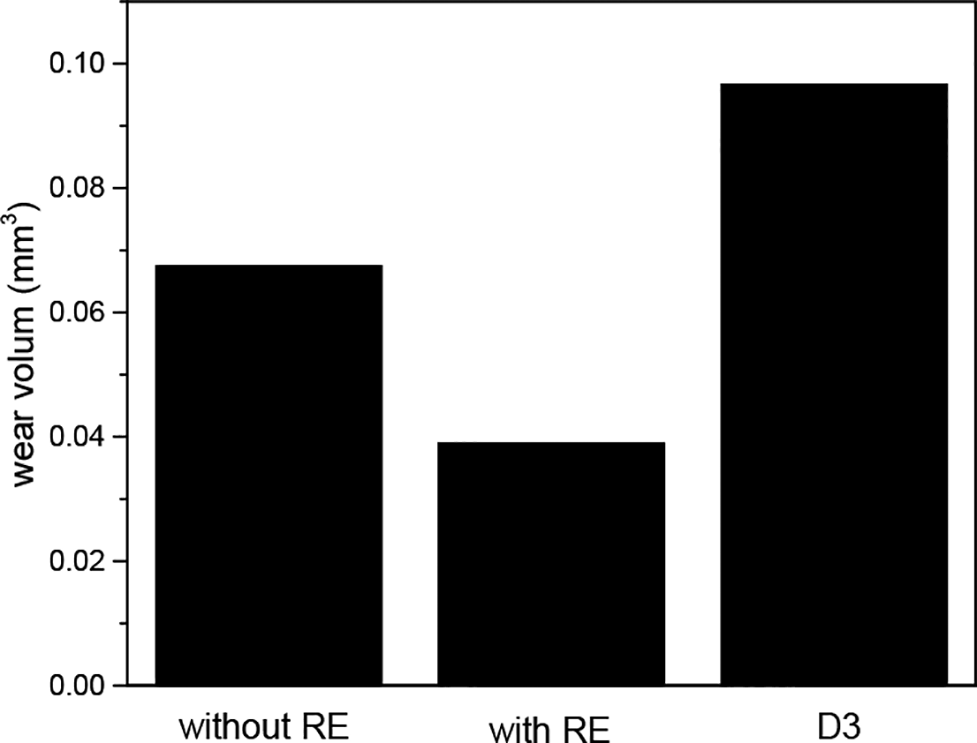
Comparison charts of volume weight losses of abrasion of two groups and comparative sample (BD2) after oil lubricating for 4 h
Volume weight losses of abrasion of different samples in each period
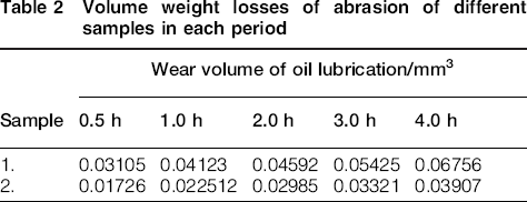
The wear tendency chart of samples is shown in Fig. 10. The widths of grinding were measured at 0.5, 1.0, 2.0, 3.0 and 4.0 h, and the wear volume was calculated by the formula of wear volume. It can be seen from the figure that different stages of wear correspond to different periods, and the differences are closely connected with the existing state of carbides, especially WC. It can be seen from the above that adding RE has significant effect on the state of carbides, so adding RE improves the abrasion performance of the cladding layer.
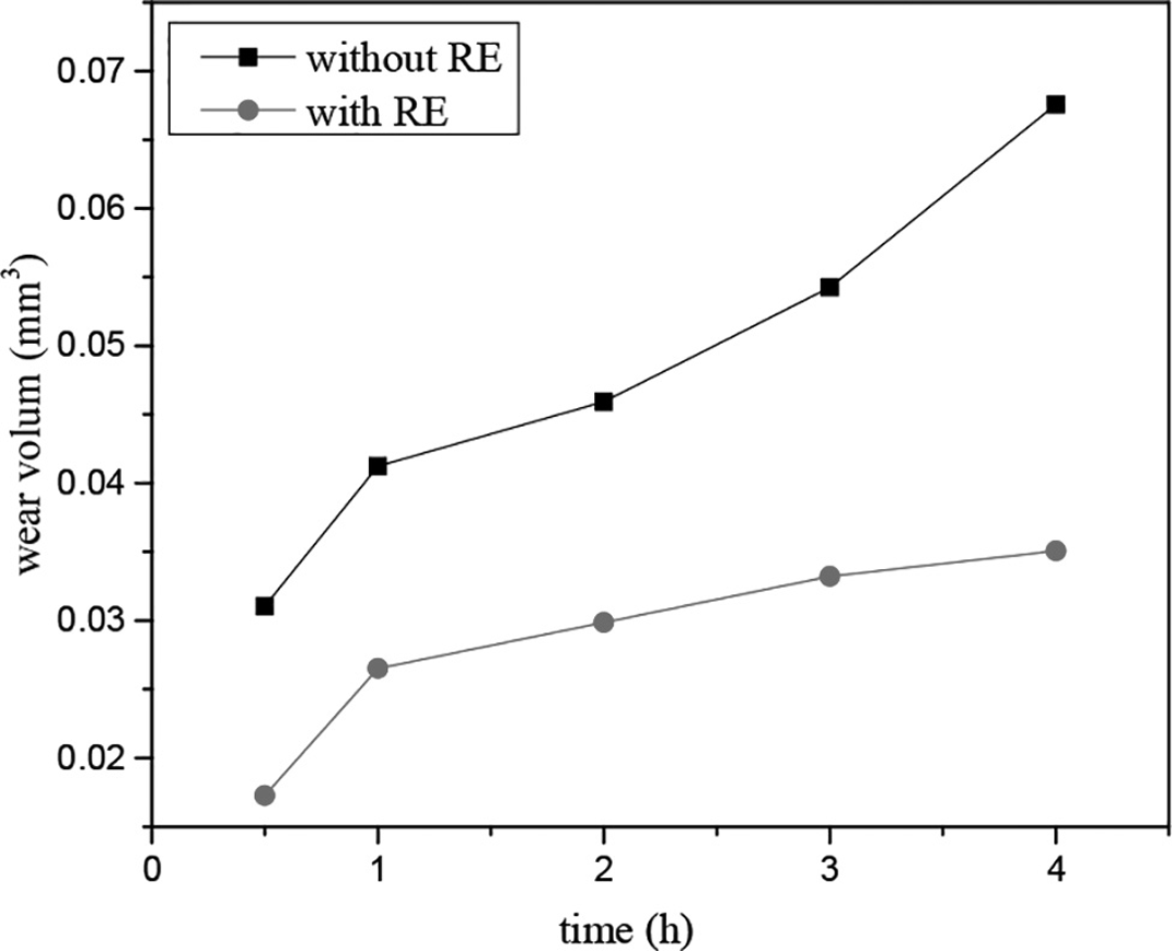
Wear tendency chart of samples with and without RE
For the first group, there is a little WC particle distributed unevenly in the composite cladding layer. As time increases, the degree of wear becomes more and more serious. Figure 11a shows the surface morphology of the sample without RE after abrasion of 4 h. There are furrows, spalling pits and elongated cuttings of significant width and depth in the figure. The strengthening mechanisms of the composite coating are solid solution strengthening and dispersion strengthening. Because of the sparse distribution of WC particle in the composite coating, there is little effect of particle reinforcement. Therefore, local plastic deformation will occur under the force of grinding rings, and because of roller compaction of the asperity of grinding rings, there forms the furrow and cutting. The metal phases near the hard particles are plastic phases. In the wear process, the hard particles surrounded by metal phase peel off as well as the plastic deformation of metal phase, and the fallen particles may cause abrasive wear. From the analysis of the sample surface morphology, the main wear mechanism is microcutting.
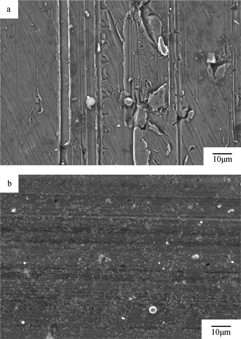
Surface morphology of sample a without RE and b with RE after abrasion of 4 h
The rare earth elements were added into the second group. It can be seen from the wear curve and the surface morphology (Fig. 11b) after abrasion of 4 h that adding RE may improve the abrasion resistance of the composite coating significantly. Because of the dispersion strengthening and solid solution strengthening effect, there are only a few furrows, and the area of wear is relatively smooth. The reasons for this phenomenon are the following. First, the nucleation particles increase significantly after adding RE, and the crystal grains are refined obviously. The precipitated phases have more hard particles, and the organisation of the coating is uniform distributed. The asperity of grinding rings can only embed low in coating, so that the coating is more resistant to plow and the wear volume is greatly reduced. Second, due to the refinement, purification and metamorphism of adding the appropriate amount of RE, the organisation of the cladding layer is refined, and the inclusions in cladding layer are reduced, which will improve the wear resistance of the cladding layer. Third, the lubricating effect of RE compounds can reduce the coefficient of friction and the effect of adhesion and plowing. What is more, the solubility of RE in the alloy is small, and most of them are presented in the grain boundaries. Therefore, adding the appropriate amount of RE strengthens the grain boundary and leads to the stress relaxation of microcrack tips on the surface and increases the resistance of crack growth, thereby reducing the degree of wear. However, when rare earth oxides gather too much at the grain boundaries, as the brittleness of grain boundaries increases, the asperity is easy to break along the direction of crack propagation, instead of making the wear increase.
These differences of structure of those two kinds of coating may be relative to RE. First, adding RE can reduce the constitutional supercooling, suppress segregation in solidification process15–16 and thus inhibit the growth of dendrites. Therefore, there is no dendrite in Fig. 3b. Second, a rare earth element with strong chemical activity is easy to react with other elements to form stable compounds, 17 so as to increase the nucleation sites of carbides in the cladding layer and the nucleation rate in solidification. It leads the grains to be fine and equiaxed, as shown in Fig. 6b. Third, rare earth has a pinning effect on the phase boundary of carbides, thereby preventing the growth of massive carbides and making the carbides in separated state. The absence of transition region around WC grains, as shown in Fig. 7c and d, may be associated with it. Fourthly, the RE can reduce the diffusion coefficient, 18 prevent diffusion of W, C to the matrix and Fe to the coating, which may decrease thickness of plane crystal, prevent the dissolution of WC particles and may be one reason for the absence of the transition region in Fig. 7c and d.
Conclusion
Adding RE does not change the categories of phases in the cladding layer. The main components of phase are still α-Fe, Fe3W3C, WC and W2C. Adding RE improves the dispersion of carbide particles in the cladding layer and reduces agglomeration and bridging of carbide particles. The particles distribute homogeneously. The dissolution of WC particles and the formation of fishbone shaped dendritic carbide are restrained. It also promotes the formation of granular carbide and refines grains. Adding RE improves the average hardness of cladding layer and stabilises the trend of it. It also reserves the WC particles in composite coating and improves the wear resistance of the cladding layer.
Acknowledgements
The authors acknowledge the financial support for this work from the State Key Development Program of Basic Research of China (grant no. 2011CB013402), the Natural Research Fund of Education Bureau of Anhui Province (grant no. KJ2012 A232) and the Key Technology R&D Program of Anhui Province (grant no. 1301021006).