
Abstract
In this paper, are described a series of tests that have been undertaken to elucidate the effects of geometry, material properties and reinforcement location on the flexural properties of laminated veneer lumber. The fracture modes are found to be a function of the properties and location of the reinforcement and ultimately the strength of bonding between the components. The use of high modulus reinforcements is beneficial to enhancing the stiffness of laminated veneer lumber, whereas lower stiffness reinforcements are beneficial for the enhancement of strength. Lowered fractions of rod and plate reinforcement are as beneficial as higher fractions of rod and plate reinforcement in reinforcing timber, provided they are judiciously positioned in the timber and have a stable bond.
Introduction
For decades, reinforcing material has been applied in different ways to structurally enhance the flexural properties of timber in construction. Peterson (1965) considered the merits of applying prestressed steel to the tensile fibre of timber beams. Stern and Kumar (1973) vertically laminated full depth steel plate reinforcements between timber beams and mechanically connected the composite elements with nails. This traditional ‘flitching’ technique has been used for decades and in this case yielded on average, a 48% increase in the flexural stiffness and a 45% increase in flexural strength relative to unreinforced timber beams. Treating timber, however, decreases the benefit of flitch reinforcements. The same tests performed by Stern and Kumar using creosote treated timber generated 20% lower values for flexural strength as compared with its untreated counterpart. The lower strength values generated from creosote treated timber are, however, compensated for by the preservation effects of the creosote. Coleman and Hurst (1974) also considered a similar geometric arrangement of steel and timber composite elements as used by Stern and Kumar. Coleman and Hurst aimed to define flexural properties based upon the contiguity of mechanical connection. The flexural properties of the composite beams did not show any trends as a function of increasing the number of nails used for connection. Coleman and Hurst believed that this was a consequence of having low variability in the numbers of nails used and indeed, they felt that the numbers of nails used were high enough to develop the full strength of the steel. Further tests reported in this paper involving flitch beams both adhesively joined and mechanically connected proved this connection technique to be superior to solely mechanically connecting. The use of full depth vertical laminates for beams in bending may not, nevertheless, be the most efficient way of reinforcing timber. Popular in the early 1900s, the vertically laminated steel–timber composite system declined in use, most probably as a direct result of the predrilling and bolting assembly procedure, which is both inefficient and time consuming (Stern and Kumar 1973). This said, the steel flitch assembly is still used extensively in the modern age, one large scale example being the Nagano Olympic Memorial Arena located in Japan (Ban et al. 1999). Whether the reinforcement truly serves any noteworthy function in the region of the neutral axis is questionable, since ineffectual reinforcement is costly, heavy and unnecessary. Jones (1997) demonstrated that reinforcing rods are almost insignificant in their contribution to strength and stiffness close to the axis of neutrality. Although a flitch plate, unlike steel rods, is a continuous and uninterrupted element, there is no apparently obvious reason why Jones’ finding should not apply. Borgin et al. (1968) situated vertical steel plates away from the neutral axis of the beam and closer to the faces where higher normal stresses develop. Borgin and co-workers compared two reinforcement configurations: reinforced compressive and tensile faces; and compressive faced reinforcements only. The motive behind reinforcing only the compression face lay in an understanding of the weaker nature of wood in compression as compared with its strength in tension. Timber failure was thereby seen by Borgin and co-workers, to be determined by compressive failure of the wood and this was indeed the logic behind locating all of the steel on the upper face. Reinforcing a beam on the compression face with a high stiffness material will increases the overall stiffness of the upper portion of a beam and bring the neutral axis higher towards the surface.
Beams reinforced on the compressive face were found to yield lower flexural stiffness values and higher centre point deflections compared to beams reinforced on both faces; however, beams reinforced only on the compressive face also withstood higher loads to failure, though here was no clearly observed advantage in terms of ductility. Ductility can be encouraged by reinforcing the tensile face. This has been shown using steel rod reinforcement (Dziuba 1985; Shchuko 1969). This way ductile plastic yield behaviour of timber in compression can proceed without the onset of sudden tensile fracture (Brunner and Schnueriger 2004). The result is that the overall ductility of reinforced timber composites is significantly improved, which is a much preferred mode of failure. Moreover, there is an increase in effectiveness as a function of a lowering timber elastic modulus (Borgin et al. 1968).
Hoyle (1975) also investigated the effects of small vertical steel laminates (toothed) on the compressive and tensile faces of flexional timber beams. Hoyle found that beams taken to failure under conditions of static flexural loading experienced buckling of the steel plate on the compressive side of the beam, which was not so marked so as to cause the timber members to separate. Certainly, this illustrates an important issue with regards to reinforcing beams. Long slender reinforcements are geometrically unstable under compression. The contiguity, strength and stability of contact between composite elements are therefore factors paramount in preventing unwanted buckling, which may indeed lead to early failure and beam instability. Whereas the mechanical connection technique employed by Hoyle was insufficient to prevent compressive buckling, the adhesive system utilised by Borgin and co-workers seemingly bonded the composite elements together satisfactorily, as compressive buckling of the steel plate was not reported. Sliker (1962) addressed fundamental issues concerning metallic laminates adhesively bonded to timber by means of a rigid epoxy system. The results of Sliker's research showed that laminating timber horizontally was more effective than vertically laminating, when equal volume fractions of reinforcing material were used. Horizontal laminae in Sliker's experiments failed in horizontal shear, while tensile fracture was the predominant failure mode for the beams reinforced with vertical metallic laminae.
Shear failure in beams laminated horizontally with fibre reinforced plastic (FRP) has been reported as a failure mode by many researchers, e.g. Dorey and Cheng (1996a), Belperio (1999) and Itagaki et al. (2003). Timber reinforced with fibre composite material decreases the stress intensity at cracks in the wood and hence restricts crack growth (Hallström and Grenestedt 1997). In this way, adhesively bonded vertical laminates can be effective in restraining failure through shear (Triantafillou 1997).
Since one of the primary objectives in reinforcing timber is to achieve the highest possible strength and stiffness improvement, the majority of researchers have pulled the reinforcements as close to the surfaces as possible by using horizontal reinforcing laminates. Research undertaken by Dorey and Cheng (1996a) concentrated on horizontally laminating the furthermost tensile fibres of timber beams with carbon and glass fibre reinforced plastics. Both carbon and glass fibre reinforced plastics resulted in improved strength and stiffness; however, the degree of enhancement did not increase linearly. Rather, as the volume fraction increased, the degree of enhancement tended towards a plateau. This clarifies that as tensile reinforcement is increased, compressive yielding becomes the determinant for the load carrying capacity. Increasing the reinforcement on the tensile face beyond an optimal fibre fraction is therefore both uneconomical and a waste of material. Further tests performed by Dorey and Cheng (1996b) involved beams reinforced on both tensile and compressive faces. A similar plateau effect on strength as a function of reinforcement fraction was taken to be due to a critical shear failure stress in the timber. Ultimately, whether failure occurs in compression or by shear, there is a critical fraction of reinforcement beyond which further reinforcement is unnecessary. Horizontal laminates on the compressive face can buckle as a function of both reinforcement slenderness and the magnitude of the stiffness differential between timber and reinforcement (Gilfillan et al. 2001). The use of lower stiffness materials as alternatives to steel and carbon fibre reinforced plastic (CFRP) may thus improve the compatibility of the timber with the reinforcement, thus reducing the opportunities for debonding and consequently, premature beam failure. This said, timber beams reinforced with high stiffness FRP materials, which do not experience debonding of the laminate, have been shown to improve the strain to failure (Chajes et al. 1995).
The objectives of this paper are to assess the flexural performance of internally reinforced laminated veneer lumber (LVL) beams using bonded-in plates and rods made of mild steel or FRP.
Materials and manufacture of composite beams
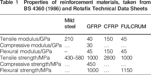
Four different materials were used to reinforce Kerto S LVL (elastic modulus 11·75 GPa, strength ∼30 MPa). These included mild steel, pultruded glass fibre reinforced plastic (GFRP), pultruded CFRP and pultruded glass fibre reinforced polyurethane (FULCRUM). All reinforcements were available in the form of plates and rods. A few properties for each of these reinforcing materials are provided in Table 1. Mild steel properties are from BS 4360 (1986), while data for the pultruded plates and rods are taken from different Rotafix Technical Data Sheets, which have been referenced at the end of the paper.
Properties of reinforcement materials, taken from BS 4360 (1986) and Rotafix Technical Data Sheets
Composite beams were manufactured in four phases (phases I–IV) for each of the reinforcing materials (Fig. 1). CB10T slow set epoxy adhesive was used for joining the composite members in each beam. Phase I composite beams were full depth flitch beams, whereby the reinforcing material was vertically laminated between two sections of LVL to a depth of 50 mm either side of the axis of neutrality. The LVL was cut to 110 mm to avoid geometric instability. Three phase I flitch beams were manufactured for each of the reinforcement types, thus totalling 12 phase I beams. Each beam was 1900 mm long. Phase II beams were manufactured by bonding together two LVL sections (1900 mm long, 51 mm wide and 110 mm deep). A 40 mm deep and 12·7 mm wide groove was then routed along the centre of the beam axis on both the tensile and compressive faces of the beam. Reinforcements of 40 mm depth were then slotted and glued into the grooves on either face. Three beams were made for each of the types of reinforcement totalling twelve phase II beams.
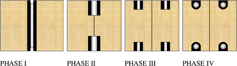
Composite beam reinforcement configurations for phases I–IV
Similarly to phase II beams, phase III beams were initially bonded together as vertically laminated LVL sections. Grooves were routed into the tension and compression faces of the beams. This time, however, grooves were routed at a depth of 20 mm and a width of 12·7 mm, with two grooves routed into each face in the centre and along the axis of each LVL segment. Reinforcing plates (20 mm deep) were then slotted and glued into the grooves located on either face. Twelve phase III beams were manufactured, three for each type of reinforcement. Phase IV beams were made up of two LVL sections vertically laminated together after which grooves were routed into the tension and compression faces using this time, a round ended router. This created a semicircular groove at the bottom of each cut. Similarly to phase III beams, two grooves were routed into both the tension and compression faces of the LVL sections. Each groove was situated at the centre of each LVL section. Reinforcements were this time inserted and glued into the grooves as circular rods for each reinforcement type except for the FULCRUM reinforcement, which was only available as square rods. Three beams were made for each of the types of reinforcement totalling 12 phase IV beams.
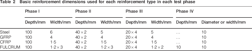
The dimensions of the reinforcements used differed as a consequence of commercial availability. The exceptions amongst the reinforcements were the FULCRUM plates, which were laminated together using the CB10T slow set epoxy. Phases I and II beams consisted of three 1·2 mm thick plates laminated together and phase III FULCRUM comprised two 1·2 mm thick plates laminated together. The reinforcing dimensions of the materials are listed in Table 2. The lengths of all reinforcements were 1900 mm.
Basic reinforcement dimensions used for each reinforcement type in each test phase
Different surface treatments were applied to the reinforcements before gluing. The mild steel was grit blasted to SA 2·5 using guidance in SIS 055900 (1967) and then coated with a primer. Plates of CFRP were covered by a protective peel ply layer that was removed before gluing. Sodium carbonate abrasive was used to scour the GFRP surface, and the FULCRUM was left untreated, since its surface was rough. The choice and designation of surface pretreatments was based upon the advice and experience of the adhesive manufacturer (Rotafix Ltd).
Section properties of phases I–IV composite beams
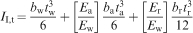
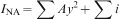
The cross-section arrangements for phase I composite beams are illustrated in Fig. 2.The second moment of area II,c and the section modulus WI,c can be calculated using equations (1) and (2) respectively. The transformed second moment of area for phase I beams II,t and the transformed section modulus WI,t are calculated using equations (3) and (4) respectively. The neutral axis (NA) is presumed to be centrally located.


 when the subscript i is representative of r, a, w,1 and w,2, and tc = tw,1.
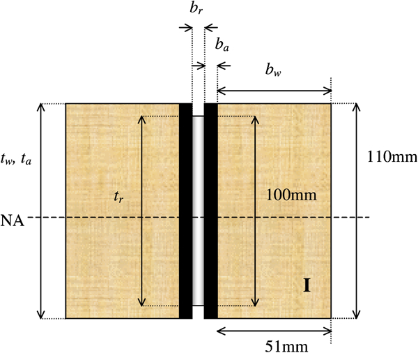
Cross-section configuration of phase I composite beams. b and t are the cross-section widths and depths respectively, and the subscripts r, a and w refer to the reinforcement, the adhesive and the wood respectively
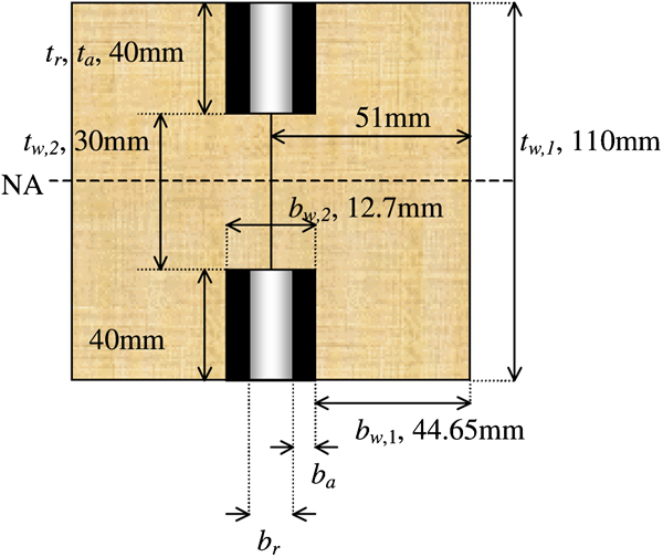
Cross-section configuration of phase II composite beams. The subscripts r, a, w,1 and w,2 refer to the reinforcement, the adhesive, the wood surrounding the routed grooves and the wood lying vertically between the routed grooves respectively
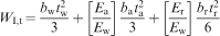
As the reinforcement and the adhesive are now located outside the composite NA, the transformed second moment of area III,t and the transformed section modulus WII,t, are calculated using the parallel axis theorem (equation (7))
 where the subscript i is representative of r, a, w,1 and w,2.
As y = 0 in phase II, for elements passing through and symmetrical about the composite NA, equation (7) expands to equation (8)


 when the subscript i is representative of r, a, w,1 and w,2, and tc = tw,1.
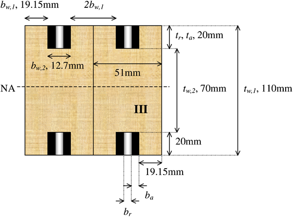
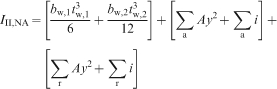
Cross-section configuration of phase III composite beams. The subscripts r, a, w,1 and w,2 refer to the reinforcement, the adhesive, the wood surrounding the routed grooves and the wood lying vertically between the routed grooves respectively
The transformed second moment of area IIII,t and the transformed section modulus WIII,t are represented in equations (13) and (14) respectively


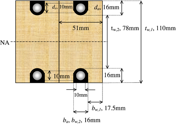
Cross-section configuration of phase IV composite beams. The subscripts r, a, w,1 and w,2 refer to the reinforcement, the adhesive, the wood surrounding the routed grooves and the wood lying vertically between the routed grooves respectively
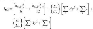
Simple geometric approximations have been applied to the calculation of the transformed second moment of area IIV,t and the transformed section modulus WIV,t. The adhesive boundary around the reinforcement is approximated to a hollow circle with an inner radius of 10 mm and an outer radius of 16 mm. Furthermore, the LVL between the routed grooves is given the inexact depth of 78 mm and thus ignores the small quantities of LVL that follow the semicircular grooves around and across the width bw,2. By approximating as such, it becomes easy to avoid second moment of area equations that are lengthy and cumbersome. As the quantities of transformed adhesive and LVL are very small, the approximations should not have any significant effects on the calculations. IIV,t and WIV,t are therefore represented by equations (17) and (18)
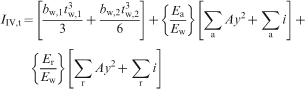

FULCRUM is the only exception to the rule. The FULCRUM rods were only available in square section but were inserted into a circular bottom groove. For the case of FULCRUM, the local second moment of area for the adhesive is calculated as πd4/64 less than the local second moment of area for the reinforcement, which is itself calculated as bt3/12.
Test conditions and specifications
Composite beams were loaded in four point bending at a crosshead rate of 2 mm min−1. The beams were tested under service class 2 conditions (having been also preconditioned at 20°C and 65% relative humidity), and the LVL retained a moisture content of approximately 12%. An linear variable differential transformer (LVDT) displacement transducer attached to the moving crosshead was used to monitor the centre point deflection. Figure 6 shows a schematic of the loading scheme.
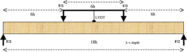
Schematic of four point bending test set-up
Failure modes of composite beams
Failure in the phase I steel–LVL composite beams initiated on the compressive face with the onset of visible buckling in the LVL (Fig. 7a). This can be related to the low yield strain of mild steel, which once surpassed, permits greater axial movement in the LVL. As the yield strength of LVL is less in compression than it is in tension, compressive face buckling was the natural primary occurrence after which, catastrophic tensile fracture was observed to follow (Fig. 7b).
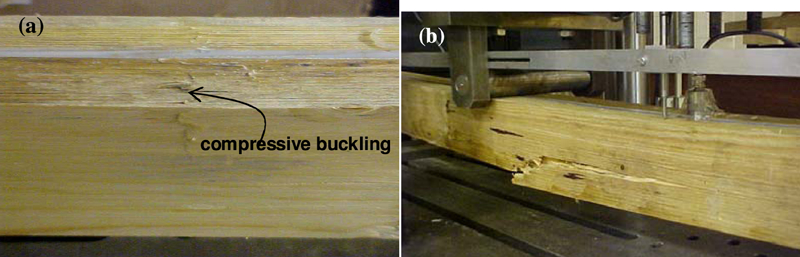
a compression face buckling in a phase I beam was followed by b catastrophic tensile fracture between the central rollers
Phase I beams from all series showed the highest resistance to failure through debonding. The lower area fraction of vertically laminating reinforcement in phase II and phase III beams resulted in a lowered resistance to interfacial debonding, which resulted in LVL failure. The reinforcement reaches its full potential only if there is effective interfacial adhesion between the composite elements, with failure being preferentially initiated in the LVL. Debonding suggests that the reinforcement is not fully contributing its strength to the overall strength of the composite as the energy stored within the composite system upon loading is released prematurely with the onset of debonding. Debonding can be considered a function of both the strength of adhesion at the reinforcement surface, as well as the difference between the stiffness of the composite elements. The strength of adhesion is itself a function of the type and mechanism of bonding. Higher modulus reinforcements will resist global movement in the LVL and adhesive to a greater extent than lower modulus reinforcements. This can result in the development of high localised interfacial stresses, which may cause interfacial failure. Debonding observed at the steel/adhesive interface and at the CFRP/adhesive interface could perhaps be explained as being a result of combining dissimilar materials with extremely contrasting stiffness properties. To the contrary, the GFRP is much less stiff than both the steel and the CFRP reinforcements, and the premature debonding could be attributed to a weak bond, which is likely to be a consequence of the manufacturing process. The pultruded GFRP is drawn through a die to yield unidirectional fibres however, the upper surface of the GFRP is comprised of randomly oriented fibres in a matrix, which contain waxy substances that aid the pultrusion process. Although mechanical roughening of the GFRP is administered as a pretreatment, it is not sufficient in removing the waxy surface layer and the bonding is relatively poor at the GFRP interface. The FULRCUM reinforcement exhibited superior adhesion qualities relative to the other reinforcements. Debonding was observed in only the phase III beams, which had the lowest area fraction of the vertically laminating reinforcement series, as well as the least number of laminates to make up the reinforcement.
It is presumed that the geometry of the phase IV reinforcements resulted in the lowest levels of interfacial failure between the reinforcement and adhesive. Though the surface area fraction is the lowest in the phase IV composites, debonding was only witnessed once on the compressive face of a CFRP reinforced composite. Vertical interfacial shear between the adhesive and the reinforcement is the most damaging to vertically laminated composites, since the surface areas exposed to this type of shearing are large. With the rod reinforcements, vertical shear exists to a much lesser extent as the geometry of the reinforcement is such that vertical shear stresses are not excessive.
Following an examination of fracture paths across the composite beams cross sections, it can be said that cracks propagating in a particular direction through the LVL and towards the adhesive reinforcement components can be redirected by the presence of the adhesive line separating the LVL from the reinforcement. Hallström and Grenestedt (1997) reported that the stress intensity of cracks is considerably reduced by the presence of fibre reinforced composite material and hence the reinforcement restricts crack growth. In the case of the reinforced LVL beams, the adhesive acts as the crack stopping material and the fracture path finds an easier route around the adhesive reinforcement insert than it otherwise would if passing through the LVL alone.
Although debonding was observed between the reinforcement and adhesive, in the majority of cases this did not lead to explosive splaying of the reinforcement. Non-explosive debonding was observed for internally reinforced timber composites and is in contrast to the explosive separations often observed with external reinforcements laminated horizontally on the surface of the timber, e.g. Johns and Lacroix (2000). Tensile load stores more strain energy at the surface and the composite (especially carbon) explodes on fracture. Rods bonded internally are strained less.
Flexural properties of composite beams
Flexural modulus
The median flexural modulus values for all tested beams are plotted in Fig. 8 with error bars indicating the upper and lower boundaries of the sample range. The flexural modulus is simply the change in stress by the change in strain determined within the linearly elastic portion of the stress–strain curve. Figure 8 includes an accompanying table, which shows the individual flexural modulus values, as well as their percentage difference from unreinforced LVL (given in brackets next to each individual value). These percentages are calculated assuming that if unreinforced, LVL will have a flexural modulus of 14 GPa as quoted in Ranta–Maunus (1995).
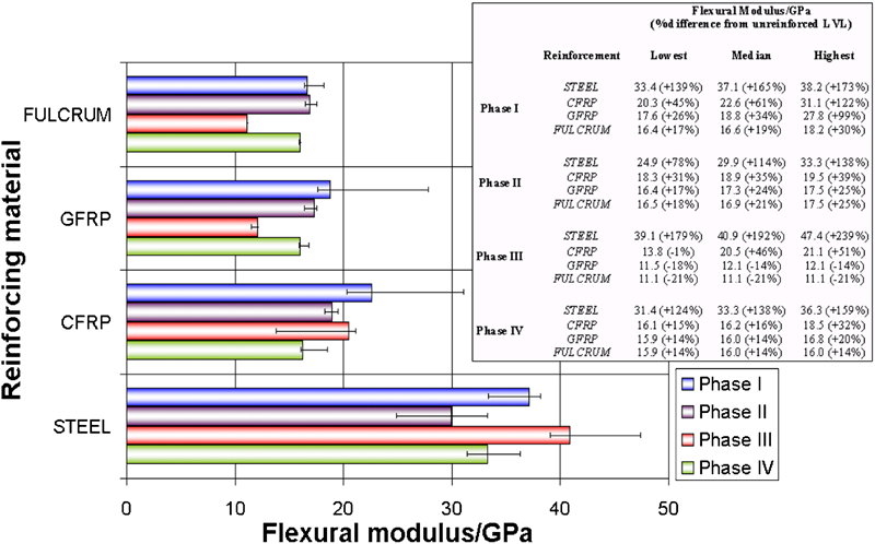
Median flexural modulus values for phase I–IV beams with error bars indicating the other two (upper and lower) values. The flexural modulus values for each beam are also given in an accompanying table with percentage differences from unreinforced LVL
The median flexural modulus values are also plotted as a function of reinforcement volume fraction indicating the upper and lower bounds with error bars (Fig. 9). Examination of Figs. 8 and 9 demonstrate that the flexural modulus is unaffected by the volume fraction of the reinforcement and yet appear to be somewhat influenced by the geometrical location of the reinforcements. Lower volume fractions of reinforcing material are often seen to do almost, as well if not better than higher volume fractions of reinforcement. Reinforcements located at the outermost fibres of a bending beam will enhance the stiffness, as there is more reinforcing material resisting tensile and compressive forces acting along the beam axis. As the reinforcement moves away from the outermost fibres and towards the axis of neutrality, the stiffening effect of the reinforcement becomes progressively reduced until it is ineffectual at the neutral axis. This is why beams reinforced with full depth vertical laminates have higher volumes fractions yet do not necessarily have proportionally larger values for the flexural modulus. Likewise, beams reinforced with lower volume fractions of reinforcement may do almost as well, if not better, because the quantity of effective reinforcement is higher than for the beams with a higher volume fraction of reinforcement.
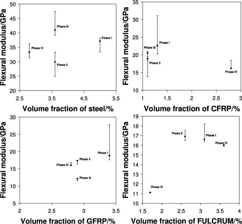
Flexural modulus for each reinforcement type plotted as a function of the reinforcement volume fraction
Negative deviations from unreinforced LVL values are noted in phase III GFRP and FULCRUM reinforced LVL composites. The curing time for CB10TSS under service class 2 conditions is 11 days, at which point it is believed that sufficient cross-linking has occurred within the adhesive. It should be noted that, although these beams were stored under service class 2 conditions, they were tested on the twelfth day after manufacture. All the other composite beams were left to cross-link for at least a few weeks before testing. It is possible that the phase III FULCRUM–LVL and GFRP–LVL composites had not cross-linked sufficiently. It is of course also possible that the LVL used for these particular beams retained an initial flexural modulus lower than the assumed 14 GPa. The reinforcement volume fraction used in phase III is low and there is also a lot of adhesive, which has a lower stiffness than the LVL and essentially lowers the beam stiffness.
Flexural strength
Median flexural strength values for all tested composite beams are plotted in Fig. 10 with error bars indicating the upper and lower boundaries of the sample range. Figure 10 includes an accompanying table, which shows the individual flexural strength values, as well as their percentage difference from unreinforced LVL (given in brackets next to each individual value). These percentages are calculated assuming that unreinforced LVL has a flexural strength of 51 MPa (Ranta–Maunus 1995). The strength values are calculated for phases I–IV beams using equation (19)

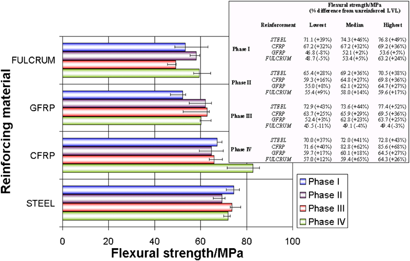
Median flexural strength values for phase I–IV beams with error bars indicating the other two (upper and lower) values. The flexural strength values for each beam are also given in an accompanying table with percentage differences from unreinforced LVL
Looking at the flexural strength values in Fig. 10, it becomes overwhelmingly clear that the composite strength is affected more by judicious positioning of the reinforcement than it is by the volume fraction of reinforcement used. In numerous instances, the strengths of the phase III and IV beams exceed the strengths of the phase I and II beams, even though the volume fractions of the phase I and II beams are higher. Using similar arguments as were used for the flexural modulus values, the flexural strength is more readily determined by the reinforcement effects at the outermost tension and compression fibres of the beam. As the highest stresses are essentially the normal axial tensile and compressive stresses, restraint imposed as reinforcement in these areas will be most effectual, with reinforcement effectiveness decreasing as it approaches the neutral axis of the composite beam.
It is hard to use Fig. 10 to make comparisons between the effectiveness of the different reinforcing materials used. This is because the volume fractions used between the reinforcing materials are so drastically different. For this reason, the transformed strengths (equation (20)) are compared and shown in Fig. 11. The strength enhancement is attributable to a material to geometric transformation and thus, regardless of the magnitude of the reinforcement volume fraction, the different reinforcing material can be compared directly to solid LVL ‘equivalents’. Comparison of the plots for each reinforcement type shows that the effectiveness of phase II–IV composite beam configurations far exceeds that of the higher volume fraction phase I beam configuration. Also, comparison between the reinforcement types demonstrates that the lower modulus reinforcing materials (GFRP and FULCRUM) actually perform, as well as if not better than their higher modulus counterparts (CFRP and steel).

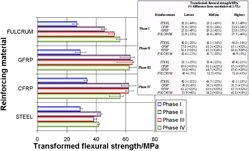
Median transformed flexural strength values for phase I–IV beams with error bars indicating the other two (upper and lower) values. The transformed flexural strength values for each beam are also given in an accompanying table with percentage differences from unreinforced LVL
Table 3 summarises the flexural properties (flexural modulus Ef, flexural strength σf and transformed strength σt) of the phase I–IV composite beams by providing the median values for each reinforcing material used in each reinforcement phase, as well as the percentage difference from unreinforced LVL (in brackets). The coefficient of variations (CoV) for Ef, σf and σt are also provided in this table. The CoV is calculated as the standard deviation of the set divided by the mean. On observing the CoV values, it can be noted that there is a degree of variation in each set. The variability between samples within sets are not particularly high and do not have any clear bias, neither towards reinforcement type nor reinforcement configuration.
Summary of median flexural properties for phase I–IV beams and for all reinforcement types
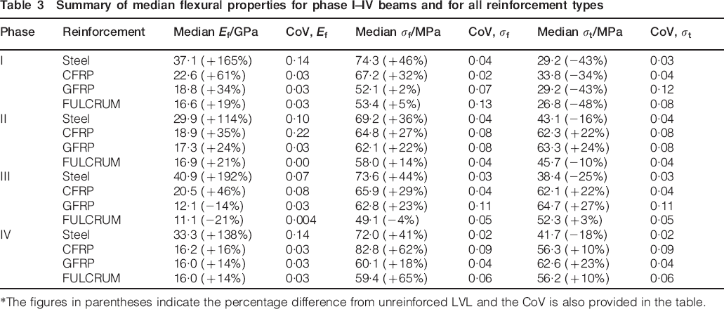
*The figures in parentheses indicate the percentage difference from unreinforced LVL and the CoV is also provided in the table.
Conclusions
A series of tests have been undertaken to ascertain the effects geometry, material properties and location have on the flexural properties of composite timber. Experimental analysis shows that the fracture mode of reinforced LVL composites is dependent upon the properties of the reinforcing material used, the quality of the adhesive reinforcement bond and the geometric location of the reinforcement. Using higher modulus reinforcements (steel and CFRP) is beneficial for enhancing the stiffness of LVL composites but is not necessarily an advantage with regards to strength over lower modulus materials (GFRP and FULCRUM). GFRP and FULCRUM enhance the strength of LVL, as well as, if not better than, CFRP and steel. The positioning of reinforcements within an LVL substrate is paramount. According to the experimental findings, lower volume fractions of rod and plate reinforcement can be used as effectively, if not better than full depth vertical laminates as long as they are located near the outermost tension and compression surfaces of the LVL.