
Abstract
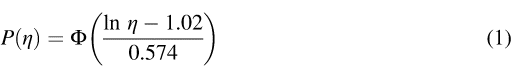
The Mw 9.0 2011 Tohoku-oki tsunami damaged 418 oil storage tanks and moved 157 of them. Using data on the severity of damage and the maximum inundation depth of the tsunami, a fragility curve representing the damage to oil storage tank plumbing is presented in this paper: P(η)= Φ ((ln η − 1.02)/0.574), where P is the damage rate, η is the maximum inundation depth in meters, and Φ is the standard normal cumulative distribution function. The existing method of predicting the movement of tanks exposed to a tsunami is validated by comparing the predicted damage with actual damage data from the 2011 tsunami. The accuracy (hit rate) is 76%.
Introduction
The Mw 9.0 11 March 2011 Tohoku-oki earthquake created a huge tsunami off the coasts of the Hokkaido and Tohoku Districts in northeastern Japan and the Kanto District in central Japan, as well as strong ground motions in the Tohoku and Kanto Districts. This event caused 18,493 casualties, with 2,683 people still reported as missing (FDMA 2013). The maximum runup height of the tsunami was 40 m in the Iwate Prefecture, Tohoku District (Mori and Takahashi 2012). Most of Japan's large oil storage tanks are located in coastal areas, and many of those in the Tohoku District exposed to the tsunami suffered various types of damage.
Although it is believed that the scale of the oil storage tank damage due to the 2011 Tohoku earthquake is the largest caused by a tsunami worldwide, the 2011 event is not the first in which such tanks suffered severe damage. Shuto (1987) introduced four cases of damage to tanks caused by tsunamis in Japan in the past. The oldest case described occurred during the MJMA 7.9 1944 Tonankai earthquake, when an empty heavy-oil tank was washed more than 300 m away by a 7-m-high tsunami in the Mie Prefecture in western Japan (Omote 1946). Shuto (1987) described the Mw 9.5 1960 Chile earthquake, the MJMA 7.9 1968 Tokachi-oki earthquake, and the MJMA 7.7 1983 Japan Sea earthquake. During the 1960 event, an oil tank in the Iwate Prefecture was floated, washed away by a 3.8-m-high tsunami, and left tilted (Chile Tsunami Joint Survey Group 1960). The 1968 tsunami caused cracks at the bottom of a heavy-oil tank in Hokkaido, resulting in oil leakage (Japan Meteorological Agency 1969). Finally, the 1983 tsunami in Korea damaged a 130-m3 light-oil tank, which was reportedly washed about 10 m from its circular concrete base and leaked 50 m3 of oil (Tsuji et al. 1984). The Hydrographic Department of Japan (1948) reported that the tsunami generated by the MJMA 8.0 1946 Nankai earthquake slid a heavy-oil tank 4 m toward the shore in the Wakayama Prefecture in western Japan; it speculated that the sliding was due to the backwash of the tsunami. FDMA (1965) reported that the tsunami caused by the MJMA 7.5 1964 Niigata earthquake led to a fire in Niigata City. The tsunami water together with underground water brought to the surface by soil liquefaction spread gasoline and other oils in the urban area, resulting in an extensive fire owing to oil ignition. The gasoline leaked from a 1,000-m3 tank that was damaged by strong ground motions. The 1964 Niigata case warns of the possibility of a large-scale complex disaster arising from strong ground motions, liquefaction, and tsunamis.
Tsunami damage to oil storage tanks has also occurred in other parts of the world. The Committee on the Alaska Earthquake, Division of Earth Sciences, National Research Council (1972) reported that the Mw 9.2 1964 Alaska earthquake tsunami devastated waterfront oil storage tanks and caused tank fires at Seward, Valdez, and Whittier, Alaska, and at Crescent City, California. The oil fires were spread by the tsunami water, resulting in considerable oil contamination from leakage and spreading. Goto (2005) reported damage caused by the Mw 9.0 2004 earthquake tsunami off Sumatra, Indonesia, at two tank farms. At a tank farm in Krueng Raya, an outlying area of Banda Aceh City, Sumatra, four tanks with capacities of 600–2,800 m3 were washed up to several hundred meters away by a 4–6-m-high tsunami. At a cement plant in Lho'nga, an outlying area of Banda Aceh, four tanks with capacities of 1,000–6,000 m3 and six 25-m3 tanks were moved. The two 6,000-m3 tanks burst through the oil-retaining perimeter wall and collided with other facilities, resulting in a catastrophic collapse. The tsunami was believed to have inundated the plant up to 10 m above the ground.
The 1964 Alaska and Niigata cases demonstrate that oil storage tanks hit by tsunamis considerably increase the risk of fires spreading to urban areas during earthquakes, in this way augmenting damage at disaster sites. Oil leakage from several tanks set afloat by the tsunami was presumed to be one of the causes of extensive fires that occurred in Kesennuma City, Miyagi Prefecture, during the 2011 Tohoku earthquake (Kesennuma Motoyoshi Fire Department 2012). Therefore, prevention and mitigation of tsunami damage to oil storage tanks is crucial in preventing earthquake fire disasters in urban areas and in mitigating the damage they cause if they do occur.
One of the most serious types of tsunami-induced damage to oil storage tanks is movement, such as sliding, floating, and drifting. Emphasis should be on prevention of tank movement because of the high risk of leakage from damaged shells and pipes attached to the tanks. The first step toward preventing or mitigating movement-induced tank damage is to predict the risk of movement for each tank that is likely to be hit by a tsunami in future earthquakes. Fujii et al. (2006) presented a method for making such a prediction (tsunami tank movement prediction method). It consists of equations developed from hydraulic model experiments to evaluate horizontal and vertical forces exerted by a tsunami on a cylindrical tank (tsunami force equations). FDMA (2009) modified these equations to better reproduce the experimental data. The tsunami tank movement prediction method was presented without validation because data on actual tank movement caused by tsunamis were not sufficient. The method's accuracy requires assessment, and validation is possible because the 2011 Tohoku earthquake left a large number of moved and unmoved tanks that were exposed to the tsunami.
After the 2011 Tohoku earthquake, the author and colleagues conducted on-site reconnaissance to survey the damage and fires caused by the tsunami, including the damage to oil storage tanks. The results were presented in a report to the National Research Institute of Fire and Disaster (NRIFD) (2011). FDMA officials disseminated a semi-nationwide questionnaire to survey the damage caused by the strong ground motions and the tsunami at facilities where flammable materials such as oil are used, produced, or stored (hazardous material facilities). The questionnaires were distributed to and collected from the municipal fire services headquarters responsible for the disaster areas, and a summary was reported in FDMA (2011). Although this report presented both the number of damaged oil storage tanks and the number of moved tanks, the author has rearranged and reviewed the raw questionnaire data by combining data from the on-site reconnaissance and from the author's questionnaire and has reassessed the number of damaged and moved tanks.
The questionnaire results are briefly summarized in the next section by listing the types of tank damage caused by the tsunami in the 2011 Tohoku earthquake and recounting the number of damaged and moved tanks. In the section following, the severe tank damage caused by the tsunami recorded by on-site reconnaissance is described via images. Although the description consists primarily of material from NRIFD (2011), this English translation should be meaningful for non-Japanese readers. The fourth section discusses the correlation between tsunami inundation depth and damage severity on the basis of the rearranged questionnaire data, where a fragility curve is first presented for tsunami damage to the plumbing of affected tanks. A rough but fact-based method is also presented to predict damage to a tank from a given maximum inundation depth. The fifth section examines the validity of the tsunami tank movement prediction method (Fujii et al. 2006) against the modified version (FDMA 2009) of the tsunami force equations on the basis of the rearranged questionnaire data. The model examination is followed by a discussion and conclusions.
The tanks discussed in this paper are basically vertical cylindrical steel tanks (cylindrical steel tanks whose axis direction is vertical). The second and fourth sections partly include transverse cylindrical steel tanks (cylindrical steel tanks whose axis direction is horizontal). The third and fifth sections discuss vertical cylindrical steel tanks only.
Questionnaire Investigation
The semi-nationwide survey conducted by FDMA took place from May to August 2011. Questionnaires were presented to the municipal fire services headquarters in 16 prefectures in which damage to hazardous material facilities was likely to have occurred in the 2011 Tohoku earthquake. In Japan, the safety of hazardous material facilities is regulated by the Fire Service Act, which FDMA implements and oversees. The fire services headquarters were requested to provide information about the following items for each of the damaged hazardous material facilities: the facility specifications, including use and size or capacity, amount of hazardous material stored at the time of the earthquake, and assessment of damage and its possible cause (ground motion or tsunami).
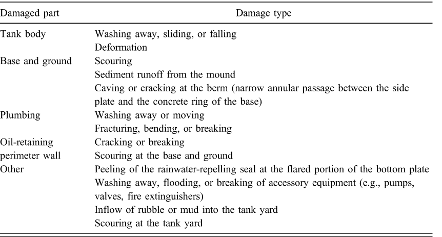
Based on responses to the questionnaire, Table 1 lists the areas of tank damage caused by the 2011 Tohoku earthquake tsunami. Although in some cases it might be difficult to judge whether the damage was caused by the tsunami or by strong ground motions, the damage that was reported to be caused by the tsunami was regarded as such. The tsunami caused damage of different types and severities to different tank parts, ranging from severe (e.g., movement) to light (e.g., flooding of accessory equipment).
Tsunami damage to oil storage tanks
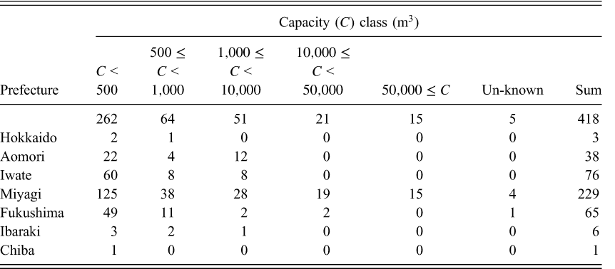
In this study, the number of damaged tanks was counted by rearranging and reviewing the raw questionnaire data as well as by combining data from the on-site reconnaissance and from the author's questionnaire investigation. Table 2 lists the number of tanks, 418, that suffered tsunami damage irrespective of type or severity. Most of them were distributed in the Iwate, Miyagi, and Fukushima Prefectures, where the height of the tsunami was greater than that observed in other areas (Mori and Takahashi 2012).
Oil storage tank damage with respect to storage capacity (capacity class)
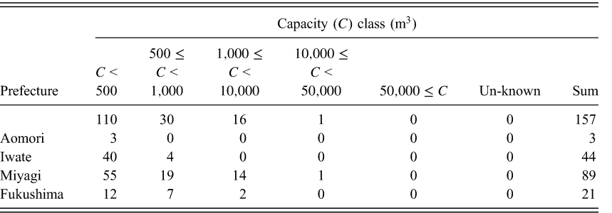
The number of tanks that suffered movement damage, such as washing away, sliding, and falling, was also counted. Table 3 shows that 157 tanks were moved in the Aomori, Iwate, Miyagi, and Fukushima Prefectures. The largest tank had a capacity of 22,000 m3 and was located in Sendai City, Miyagi Prefecture. According to the property owner, the tank was empty at the time of the earthquake and floated temporarily when exposed to the tsunami, with a maximum water level (maximum inundation depth) of 2.65 m, measured from the top of the tank mound. The largest of the nonempty tanks moved by the tsunami in the Miyagi Prefecture had a capacity of 5,900 m3 and stored 1,200 m3 of heavy oil at the time of the earthquake. This tank was located in Ishinomaki City and was reported to have been moved onto an offshore breakwater with a maximum inundation depth of approximately 7 m. The tank was broken, resulting in leakage of all stock. The largest of the tanks moved by the tsunami in the Iwate Prefecture were three 990-m3 tanks, each of which stored 510 m3 of crude oil. These tanks were located in Kuji City and were reported to have been exposed to the tsunami with a maximum inundation depth of approximately 8.5 m. In the Fukushima Prefecture, the largest of the moved tanks were two 9,800-m3 tanks located in Minami-Soma City. Their stockpiles at the time of the event are unknown. One of the tanks is reported to have slid 5 m from its original position and the other to have slid off its the mound.
Oil storage tank movement with respect to storage capacity (capacity class)
On-Site Reconnaissance
This section describes the severe tsunami damage to oil storage tanks at two sites, as reported by NRIFD (2011), which describes the results of the on-site reconnaissance conducted by the author and colleagues. Only the damage at a fishing port in Kesennuma City and at a refinery in Sendai City, both of which are located in the Miyagi Prefecture, is described, although severe tank damage occurred at many other sites. These locations were chosen for the following reasons. A tank in Kesennuma drifted from its original location 2.4 km—the longest distance observed for tanks affected by the 2011 Tohoku earthquake tsunami—and the refinery in Sendai is the largest tank farm in the tsunami-inundated area.
Fishing Port in Kesennuma
According to the Kesennuma Motoyoshi Fire Department, 22 of the 23 oil storage tanks that were located on the landfill west of the Kesennuma fishing port were washed away. The capacities of the 23 tanks ranged from 40 to 3,000 m3. The single tank that was not moved was a 100-m3 transverse cylindrical tank. Tank movement resulted in 11,521 m3 of oil leakage, including 7,350 m3 of heavy oil, 498 m3 of kerosene, 1,958 m3 of light oil, and 1,535 m3 of gasoline. The tsunami inundation depth data compiled by the City Bureau, Ministry of Land, Infrastructure, Transport and Tourism, Japan, indicated the maximum inundation depths at the tank sites in Kesennuma to be 6–10 m.
Figure 1 shows the movements of the 12 tanks found in Kesennuma after the earthquake. The arrows point from the original tank location to the location where the tank was found. Tank A moved the largest distance (2.4 km) from its original location. Figures 2a and 2b show respectively structural damage to Tank A and Tank B (from Figure 1). The side plate of tank A was deformed and that of tank B was cracked.
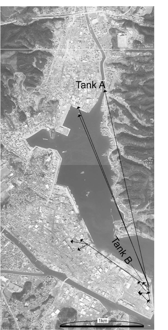
Movement of 12 tanks found in Kesennuma after the earthquake. The arrows point from the original tank location to the location where the tank was found. (Adapted from NRIFD 2011; image by Digital Japan Web System, Geospatial Information Authority of Japan.)
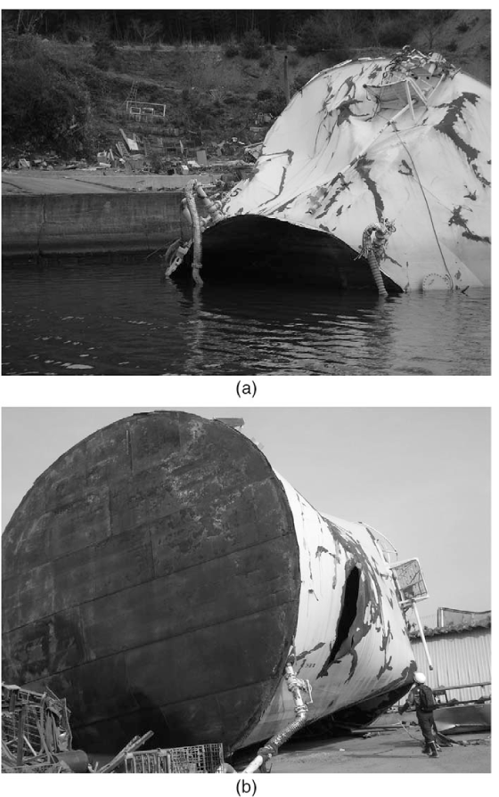
(a) Structural damage to Tank A; (b) structural damage to Tank B. The locations where the tanks were found are shown as A and B in Figure 1. (Images by Dr. Kiminori Araiba, NRIFD.)
Refinery in Sendai
The refinery shown in Figure 3a is located in Sendai and was inundated to depths of 0.6–5 m, according to the survey conducted by the refinery. In Area F, a fire occurred at the tank truck shipping facility approximately 6 hours after the earthquake. This fire spread across several oil storage tanks and lasted for approximately four days. The tsunami was considered to be one of the causes of the fire. A large amount of oil leaked in areas L1 and L2 and was impounded inside the oil-retaining perimeter wall, which is shown by the dark spots in Areas L1 and L2 in Figure 3a. According to the refinery, approximately 4,400 m3 of heavy oil leaked from a shipping-oil line bent by the tsunami in Area L1 and approximately 3,900 m3 of heavy oil leaked from a tank-attached pipe cracked by the tsunami in Area L2. Both areas were inundated to a depth of 4 m.
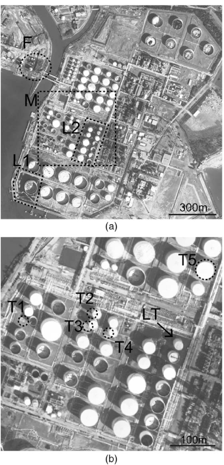
(a) Refinery in Sendai, Miyagi Prefecture: F, location of extensive fire; L1 and L2, locations of large oil leaks; M: location where five tanks moved. (b) Close-up of area M: T1–T5, moved tanks; LT, tank from which a large amount of oil leaked. (Images by Digital Japan Web System, Geospatial Information Authority of Japan.)
The tsunami moved five tanks (T1 through T5) in Area M, as shown in Figure 3b. Dotted circles in the figure indicate the original positions of the moved tanks. The capacities of T1, T2–T4, and T5 were 3,000, 5,400, and 22,000 m3, respectively, and all the tanks were empty at the time of the earthquake. The maximum inundation depths were 3.7, 3.8, and 2.7 m for T1, T2–T4, and T5, respectively. The pipe attached to Tank LT suffered cracking (Figure 4) and leaked 3,900 m3 of heavy oil.
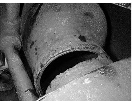
Tank LT pipe (from Figure 3b) cracked by the tsunami. Approximately 3,900 m3 of heavy oil leaked from the crack. (Image by Dr. Haruki Nishi, NRIFD.)
The tsunami damaged not only the tanks and their plumbing but also their bases. Figure 5 shows the large-scale scouring that occurred at the base and ground of a tank located near Tanks T2–T4.
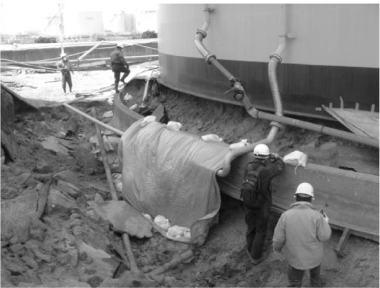
Scouring at the base and ground of a tank located near Tanks T2–T4 (from Figure 3b). (Image by author.)
Correlation of Inundation Depth and Damage
When the semi-nationwide questionnaire investigation was conducted by FDMA, the author distributed his questionnaire to the municipal fire-services headquarters together with FDMA's questionnaires. The author's questionnaire requested the respondents to indicate the maximum inundation depth not only for oil storage tanks that suffered tsunami damage but also for tanks that were inundated but not damaged. Data on the maximum inundation depth were collected for some damaged and nondamaged tanks, although the rate of collection for the author's questionnaires was lower than that for the FDMA's. FDMA conducted an additional questionnaire investigation to obtain data on the maximum inundation depth at oil storage tank sites for some of the municipal fire-services headquarters in the Aomori, Iwate, and Miyagi Prefectures after its semi-nationwide questionnaire investigation. These data for tanks at the refinery in Sendai were also collected through the author's on-site reconnaissance. Eventually, data on maximum inundation depth were collected for 337 tanks and correlated with the severity of damage.
Figure 6 shows the correlation between maximum inundation depth and severity of damage. Squares (n = 158) indicate tanks that were not moved and whose plumbing was safe. Triangles (n = 85) indicate tanks that were not moved but whose plumbing was damaged. Circles (n = 94) indicate tanks that were moved and consequently whose plumbing was most likely to be damaged. For maximum inundation depths less than 2 m, most tanks were safe, although some might have suffered minor damage. Most of the tanks that experienced a maximum inundation of 2–5 m suffered damage to their plumbing but were not moved, although some of the moved tanks were also included in this category. At maximum inundation depths of greater than 5 m, most tanks were moved. Figure 6 provides a rough but easy-to-use method of predicting damage caused by a tsunami to an oil storage tank from a given maximum inundation depth.
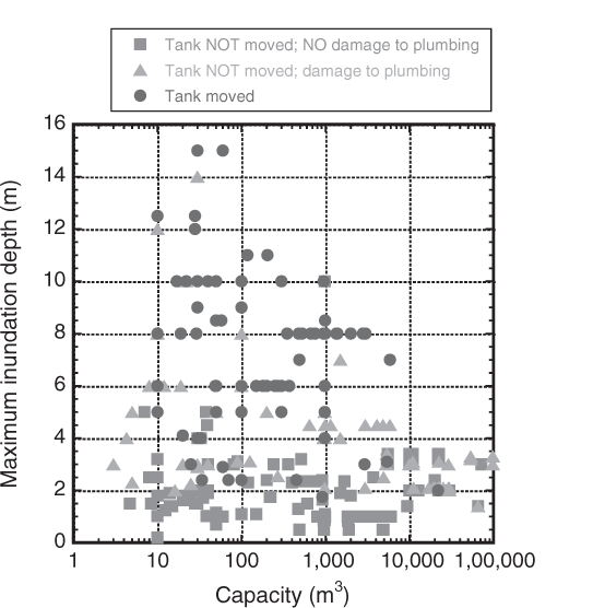
Correlation of maximum inundation depth and severity of damage to oil storage tanks. The inundated tanks are indicated by symbols representing the differing severity of damage.
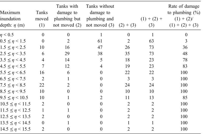
Table 4 presents the rate of plumbing damage correlated with maximum inundation depth. Moved tanks were most likely to suffer damage to their plumbing, so the rate of plumbing damage was calculated by dividing the sum of the number of tanks that were moved and the number of tanks that suffered plumbing damage but were not moved by the total number of tanks. For maximum inundation depths of greater than 6 m, the damage rate was almost 100%. These observed damage rates were modeled by the log-normal cumulative distribution function. As a result, the model of the fragility curve is presented as follows:
Damage to tank plumbing with respect to maximum inundation depth
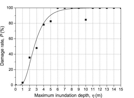
Rate of damage sustained by tank plumbing (squares) and the fragility curve (solid line) modeled by the log-normal cumulative distribution function: P(ηmax) =Φ ((ln η − 1.02)/0.574), where Φ is the standard normal cumulative distribution function. The damage rate was calculated by dividing the number of tanks that moved or that suffered plumbing damage by the total number of tanks.
Figure 8 shows the relationship between tank movement and oil storage rate (the ratio of the quantity of oil stored at the time of the earthquake to the tank capacity) for 90 moved tanks. Squares (n = 20) and circles (n = 70) indicate tanks that were inundated to depths of less and greater than 5 m, respectively. Small (capacity < 100 m3) and large (capacity > 500 m3) empty tanks were moved at a maximum inundation depth of less than 5 m. Large nonempty tanks were not moved by this class of tsunami. At maximum inundation depths of greater than 5 m, both small tanks and large nonempty tanks were moved. Figure 8, again, provides a rough but easy-to-use method of predicting tank movement caused by a tsunami from a given maximum inundation depth and a given oil storage rate.
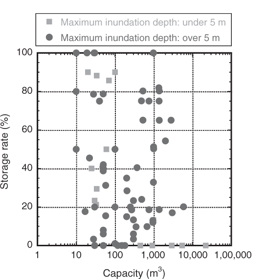
Correlation of oil storage rate (proportion of tank capacity used) and tank movement. Only tanks that moved are plotted, with circles and squares representing different maximum inundation depths.
Validation of the Tsunami Tank-Movement Prediction Method
In this section, the validity of the tsunami tank-movement prediction method (Fujii et al. 2006) with the modified version of the tsunami force equations (FDMA 2009) is examined by verifying the predictions obtained using the method against the actual damage data from the 2011 Tohoku earthquake tsunami. First, the method is outlined and then its validity is discussed.
Tsunami Tank-Movement Prediction Method
Using the method presented by Fujii et al. (2006), the risk of sliding and floating for a vertical cylindrical tank exposed to a tsunami is evaluated by the sliding safety factor FsS and the floating safety factor FsF, which are defined by the following equations:


The tsunami force equations to calculate FtH and FtV were empirically developed from the hydraulic model experiments by Fujii et al. (2006) and their original forms are as follows:
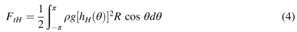
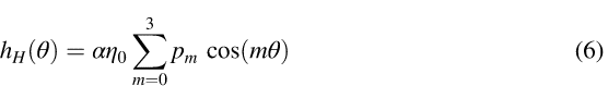
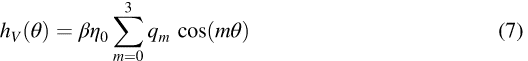
In Equation 4, the horizontal force exerted on the tank by the tsunami is modeled by the integration of the hydrostatic pressure for a hypothetical water-height distribution over the tank side plate, which is denoted hH(θ), θ being the azimuth angle with respect to the center of the tank bottom and θ being 0 for the direction from which the tsunami propagates. R, ρ, and g are the radius of the tank, the density of the tsunami water, and the acceleration due to gravity, respectively. hH(θ) is described by Equation 6, where η0 is the maximum inundation depth that would be observed if a tank were absent. The θ dependency of hH(θ) is modeled as a series of cosine functions, and the expansion coefficients pm were determined from the water-height data measured at the side plate of the tank models in the hydraulic model experiments, where a model tank was exposed to a simulated tsunami wave: p0 = 0.68, p1 = 0.34, p2 = 0.015, and p3 = −0.035. These pm values give a normalized distribution. α controls the amplitude of, hH(θ) and its value was determined to be 1.8 so that the peak values of the horizontal force exerted on various model tanks exposed to simulated tsunamis with different water velocities would be included.
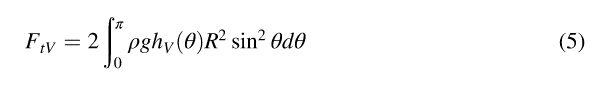
The vertical tsunami force is modeled by Equation 5 similarly to that for the horizontal tsunami force. In Equation 5, the hydrostatic pressure for a hypothetical water-height distribution, hV (θ), is integrated over the tank bottom; hV (θ) is described by Equation 7 like hH(θ), where the expansion coefficients qm give a normalized distribution and β controls the amplitude. The values of qm were determined from the water-pressure data measured at the bottom of the tank models in the hydraulic model experiments: q0 = 0.72, q1 = 0.308, q2 = 0.014, and q3 = 30.042. The value of β was determined to be 1.2 by the same approach used for α.
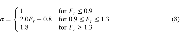
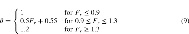
Equations 4–7 do not require water velocity for the determination of tsunami force. This is the result of α, β, pm, and qm having been determined so that the values predicted by the equations would not fall below the peak values of the tsunami force measured from the simulated tsunamis with different water velocities. The lack of need for water velocity is convenient in practice because it is not predicted in most of the tsunami hazard assessments conducted in Japan. A shortcoming of excluding water velocity is that the tsunami force and the consequent damage are likely to be overestimated. To improve the accuracy of evaluating the tsunami force by taking water velocity into account in a simplified manner, FDMA (2009) presented a modification for α and β given by the following equations:

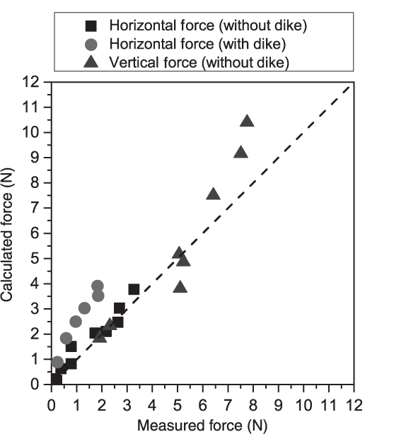
Comparison of the tsunami force measured in the hydraulic model experiments and the force calculated from Equations 4–9. The term “dike” refers to the oil-retaining perimeter wall. In the hydraulic model experiments conducted by Fujii et al. (2006), the horizontal tsunami force was measured for two cases: (1) the model dike is placed around the model tank and (2) the model dike is not placed around the model tank. (Adapted from FDMA 2009 and Dr. Naoki Fujii, pers. comm.)
Validation of the Tsunami Tank-Movement Prediction Method
The author's questionnaire, distributed to municipal fire-services headquarters when the semi-nationwide questionnaire investigation was conducted by FDMA, asked respondents to indicate the weight and radius of the tank, the quantity of the oil, and the maximum inundation depth of the tsunami at the tank. These data are needed for the tsunami tank-movement prediction using Equations 2–7. FDMA also collected data needed for tsunami tank-movement prediction through an additional questionnaire investigation conducted after the semi-nationwide investigation. The required data were also collected from the refinery in Sendai through the author's on-site reconnaissance. Data were collected for 194 tanks, the movement predicted for which by Equations 2–7 was compared with the actual damage situation. In the prediction, tanks for which the values of FsS were less than 1 were assumed to be moved. Because it was not possible to obtain data on water velocity from the questionnaire investigation, Fr was assumed to be less than 0.9, so α and β were set to 1. For solving Equations 6 and 7, the maximum inundation depth (η0) in the absence of tanks is required, which could not be known. The variable η0 was replaced by η, which is the maximum inundation depth in the presence of the tanks. The variables μ and ρ were assumed to be 0.6 and 1.02 × 10³ kg/m3, respectively.
Figure 10 shows the resistance force for sliding with respect to the horizontal tsunami force. When that force is larger than the horizontal tsunami force, it is predicted that tanks will not move. This prediction was accurate for 118 tanks that did not move, whereas the damage for one tank that was moved was incorrectly predicted by the calculations. When the horizontal tsunami force exceeds the resistance force for sliding and the resistance force is not negative, it is predicted that a tank will slide but not float. The movement of one tank was successfully predicted, but 12 tanks that did not move were predicted to move, indicating an incorrect prediction. When the resistance force for sliding is negative, it is predicted that the tanks will float. The movement of 28 tanks was successfully predicted, but 34 tanks that did not move were predicted to move, indicating an incorrect prediction once again.
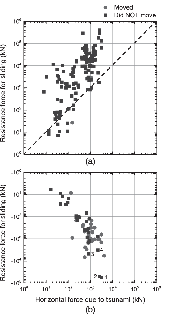
Comparison of predicted and actual tank movement. Circles and squares denote tanks that actually moved and tanks that did not move, respectively. (a) The upper triangular portion, where the calculated resistance force is larger than the horizontal tsunami force, corresponds to the prediction that the tank will not move; the lower triangular portion, where the calculated horizontal tsunami force is larger than the resistance force, corresponds to the prediction that the tank will slide. (b) Negative calculated resistance force, corresponding to the prediction that the tank will float.
Of the 30 tanks that actually moved, 29 were predicted to move, and damage to one tank was incorrectly predicted. Of the 164 tanks that did not move, 118 were predicted not to move; the remaining were predicted to move, and their damage was overestimated. On the whole, the prediction for the 147 tanks whose predicted damage was compared with the actual damage was successful, indicating a hit rate of 76%.
Discussion
In this section, the validity of the tsunami tank-movement prediction method is further discussed. The method represented by Equations 2–9 can be used in predicting the movement of oil storage tanks likely caused by future tsunamis for the following two reasons: (1) the hit rate of prediction for tank movement caused by the 2011 Tohoku earthquake tsunami was 76%; (2) most of the incorrectly predicted cases were safe errors in that the tanks that did not move were predicted to move. An adverse incorrect prediction that a tank that actually moved would not move occurred in only one case. A safe incorrect prediction would be tolerable in hazard assessments, but an adverse incorrect prediction would not be because the former leads to risk overestimation whereas the latter leads to risk underestimation.
Although overestimation is preferable to underestimation, the incorrect prediction leading to excessive overestimation should be eliminated. In this context, Tanks 1–4 in Figure 10 are discussed because the prediction for them was substantially different from the observed damage situation. The resistance forces for sliding calculated for these four tanks were negative with very large absolute values; that is, they were all predicted to float but none actually moved. Three of the four tanks were large with capacities greater than 50,000 m3 (Table 5). An incorrect prediction for such large tanks may significantly reduce the efficiency of tsunami hazard assessment because the contribution of large tanks to the overall hazard is potentially significant. The method needs to be improved to predict the movement of large tanks more accurately.
Specifications and data for Tanks 1–4 shown in Figure
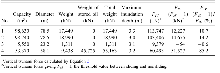
Vertical tsunami force calculated by Equation
Vertical tsunami force giving F sS = 1, the threshold value between sliding and nonsliding.
The calculation of overly large vertical tsunami forces by Equations 5 and 7 may be the cause of a significant incorrect prediction of movement for large tanks. The vertical tsunami force on Tanks 1 and 2 (Figure 10), both of which were empty, was calculated to be five times the total tank weight, thus predicting floating. The vertical force on Tank 4, which had an oil storage rate of about 10%, was also larger than the total weight of the tank.
The overestimation of vertical forces is derived from the hydraulic model experiments from which Equation 7 was developed. The coefficients β and qm were determined from water pressure measured by hydraulic gauges attached to the bottom of the model tanks. In the measurements, the model tanks attached to a six-component force sensor were suspended to create clearance between the floor and the bottom of the tank. This means that Equations 5 and 7 provide the vertical tsunami force where the entire surface of the tank bottom is subjected to water pressure. The question is whether such a situation actually occurred when the tanks were exposed to the tsunami flow. This is likely for small tanks, which have a relatively large aspect ratio (the ratio of tank height to tank diameter) and so easily tilt when exposed to tsunami flow. Once a tank tilts, water flows between the tank base and bottom, and a significant part of the tank bottom is subjected to water pressure. On the other hand, large tanks generally have a small aspect ratio and are presumably difficult to tilt, so it is unlikely that extensive parts of the tank bottom are subjected to water pressure even if the tank is exposed to a tsunami. If this is the case, Equations 5 and 7, which assume that the entire surface of a tank bottom is subjected to water pressure, overestimate the vertical tsunami force, particularly for large tanks.
Figure 11 shows the ratio of the vertical tsunami force calculated by Equations 5 and 7 to the horizontal tsunami force calculated by Equations 4 and 6, showing its exponential increase with increasing tank diameter. This increase can be understood by the difference in the R dependence of Equations 4 and 5; the vertical force is proportional to the area of the tank bottom whereas the horizontal force is proportional to the tank circumference. For larger tanks with a diameter of greater than 20 m (a capacity of greater than 5,000 m3), the vertical force is calculated to be more than 10 times the horizontal force. Accurate estimation of the vertical tsunami force is critical in making precise movement predictions for large tanks.
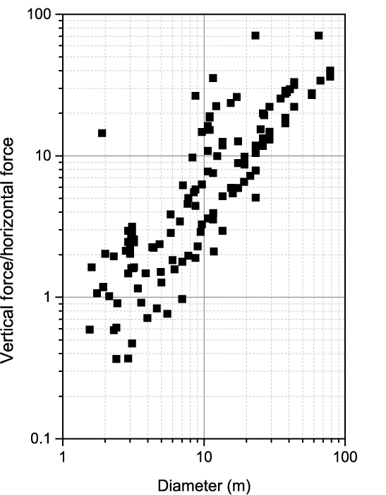
Ratio of calculated vertical tsunami force to calculated horizontal tsunami force for different tanks. Equations 4 and 6 and 3 and 5 were used to calculate the respective vertical and horizontal forces.
Table 5 indicates the vertical tsunami force [FtV (FsS = 1)] that gives FsS = 1, the threshold value between sliding and nonsliding, and the ratio of FtV (FsS = 1) to FtV . For Tanks 1 and 2, each with a capacity of 1,00,000 m3, the fact that the tanks were not moved suggests that the vertical force actually exerted on the tank bottom should have been less than 10–14% of the force calculated by Equations 5 and 7, implying that a small fraction of the tank bottom was subjected to water pressure. One of the key ways to improve estimation accuracy for vertical tsunami force for large tanks is to examine how and how far water enters into the area between the tank base and bottom.
Conclusions
The 2011 Tohoku earthquake tsunami damaged 418 oil storage tanks located along the Pacific coast of the Hokkaido, Tohoku, and Kanto Districts of Japan. A wide variety of damage was observed, including movement and deformation of tank bodies, tank base and ground scouring, sediment runoff from the tank mound, pipe movement or structural fracture, oil-retaining perimeter wall cracking, and perimeter wall base and ground scouring. In total, the tsunami moved 157 of 418 tanks.
By comparing the severity of tank damage with the maximum inundation depth of the tsunami, a fragility curve projecting the damage to the plumbing of the tank was presented in terms of maximum inundation depth (Equation 1). A rough but easy-to-use method of predicting tsunami damage to an oil storage tank from a given maximum inundation depth was presented, with the following predictions:
For maximum inundation depths of less than 2 m, most tanks are safe, although some might suffer minor damage. For a maximum inundation depth of 2–5 m, tanks suffer damage to their plumbing and small tanks (capacity < 100 m3) and empty larger tanks may move; nonempty larger tanks will not move. For maximum inundation depths of greater than 5 m, most tanks will move.
The validity of the tsunami tank-movement prediction method (Fujii et al. 2006) and that of the modified version (FDMA 2009) of the tsunami force equations (Equations 2–9) were evaluated. A comparison of the method's predictions with the actual damage data from the 2011 Tohoku earthquake tsunami indicated a hit rate of 76%. The method was observed to overestimate tank movement; however, almost every incorrect prediction was a safe error (a tank that was predicted to move did not). Because of its high accuracy and its tendency to provide safe predictions, the method has potential applications in practical prediction of oil storage tank movement caused by tsunamis resulting from earthquakes.
The method's incorrect prediction of movement is attributed to overestimation of the vertical tsunami force exerted on the tank bottom, which is significant for large tanks (capacity > 50,000 m3). Because large tanks have a disproportionate impact on overall hazard assessment, improving the accuracy of estimates of vertical tsunami force for large tanks is one important way to improve prediction of tsunami damage to oil storage tanks.
Footnotes
Acknowledgements
The comments by an anonymous reviewer and the responsible editor greatly helped improve the manuscript. The author expresses his sincere gratitude to all individuals, including his colleagues at the National Research Institute of Fire and Disaster (NRIFD), who cooperated in the questionnaire investigation and the on-site reconnaissance. The author appreciates the efforts of the officials of the Fire and Disaster Management Agency (FDMA) in conducting their questionnaire investigations and is grateful to them for allowing him to use their raw data. Dr. Kiminori Araiba of NRIFD provided data and images obtained during his on-site reconnaissance in Kesennuma. Discussions with Naoki Fujii of Tokyo Electric Power Services Co., Ltd., and with Takashi Miyauchi of the Hazardous Materials Safety Techniques Association (a former FDMA official who participated in the questionnaire investigations), were very helpful.