The deadman theory is composed of two angles: and , and it is recommended that both be less than or equal to 45°. Based on this theory, surgeons insert the anchor at 45°. However, the biomechanical studies show controversial data. We reviewed the original article and the biomechanical studies in the literature. We further performed three additional studies: 1) a finite element analysis to calculate the pullout strength of thread-less anchors inserted at 45°, 90°, and 135° to the polyurethane foam; 2) the same pullout test using thread-less anchors and the polyurethane foam; and 3) the same pullout test using metal threaded suture anchors and the simulated cortical bone. From the review and the additional studies, we came to the following explanations for the controversy: #1, the trigonometric calculation is not always applicable because of bone deformation; #2, insertion angle of 45° is the best for a thread-less anchor, but not for a threaded anchor; #3, is true, but it is not equivalent to inserting an anchor at 45°. In conclusion, insertion angle of 45° is the strongest for a thread-less anchor, but 90° is the strongest for a threaded anchor. The pullout strength depends on the inclination of the anchor, friction of the anchor–bone interface, and quality of the bone.
Since Burkhart reported the deadman theory in 1995 [1], many biomechanical studies have been reported [2–8]. There is much controversy about this theory these days [9–13] because most of the biomechanical studies have reported data that are not consistent with this theory. According to the deadman theory, an anchor inserted at 45° shows the greatest pullout strength theoretically, whereas the biomechanical pullout studies have shown that anchors inserted at 90° [3], 135° [5], or between 105° and 135° [4] show the greatest pullout strength. Recently, Editorial of the Journal of Arthroscopy cited the argument between the authors of biomechanical studies and Burkhart [14]. However, these arguments or Editorial do not seem to help the readers understand why there are discrepancies between the deadman theory and the biomechanical studies.
When we pull out a pin from the board, we pull it in the direction of the pin insertion because we intuitively know that it would be the easiest way. If we pull the pin perpendicular to it, we have to break the board to pull it out. This is simply based on the friction of the pin and the board. Pulling the pin in the direction of its insertion requires a much smaller force than breaking the board because the friction between the pin and the board is very small. However, if the friction happens to be greater than the force required to break the board, it would be easier to pull the pin perpendicular to it rather than pulling it in the direction of its insertion. Likewise, the deadman theory or pullout strength of an anchor from the bone seems to depend on the friction between the anchor and the bone and also depends on the strength of the bone. We wrote this current concepts article with some new studies added to have a better understanding of this controversial topic.
Deadman theory
Deadman theory. There are two angles to be considered in this theory: 1) direction of the force through the deadman wire (suture) = θ2; and 2) inclination of the deadman (suture anchor) = θ1. (Modified from Burkhart, 1995) [1].
A “deadman” is a heavy plate, wall, or block buried in the ground that acts as an anchor for a retaining wall, sheet pile, etc., by a tie connecting the two. The deadman theory, first introduced by Burkhart in 1995 [1], is the application of this deadman concept to the suture anchors that we use during surgery. He noticed that in the South Texas, ranchers used a deadman (a rock) to keep the fence line tight against the pulling force. If the deadman is too close to the fence post, the post may lean away from the deadman until the horizontal component of the force through the deadman wire and the force through the fence wire reach equilibrium. At this point, the deadman wire is inclined at approximately 45°. Based on this observation, he applied the deadman construct to the suture anchor fixation, and called it the deadman theory. A suture anchor acts as the deadman and the sutures are the deadman wires. There are two angles in this concept: 1) the inclination of the deadman wire (suture) and 2) the inclination of the deadman (suture anchor) (Fig. 1). He termed the former “the tension reduction angle ()” and the latter “the pullout angle ()” (Fig. 2). According to his original article, “Ideally, and should both be less than or equal to 45°.” These angles need to be discussed separately.
and . The pullout angle () is defined as an angle between the perpendicular line to the long axis of the anchor and the suture. The tension reduction angle () is defined as an angle between the bony surface and the suture. (From Burkhart 1995) [1].
Tension reduction angle ()
As the tendon is pulled medially, the sutures passing through the tendon incline until the retraction force by the tendon and the horizontal component of the force through the sutures reach equilibrium (Fig. 3). This inclination of the suture through the cuff tendon is . was well described and discussed in the original article [1]. As Burkhart observed in the South Texas ranch, is widely accepted, and no argument follows about .
Inclination of the suture (). As the tendon is retracted medially (a), the suture inside the tendon inclines until the retraction force and the horizontal component of the force through the suture reaches equilibrium (b). Then, the medial retraction of the tendon stops.
Pullout angle ()
On the other hand, is quite controversial. In order to make our explanation simple, we fix as 45° in the rest of this article. All the directions of anchor insertion and pulling force through the suture are described based on the protractor for consistency (Fig. 4). Thus, the direction of suture pull is fixed at 135°. Under this condition, the anchor inserted at 45° is perpendicular to the line of pull, which makes equal to 0° and would theoretically be most resistive to pullout force. The anchor inserted at 135°, on the other hand, makes equal to 90°, which seems to be theoretically the least resistive construct to pullout force. The anchor inserted at 90°, just between 45° and 135°, makes equal to 45°, which would be less resistive than the 45° anchor, but more resistive than the 135° anchor. Because of these theoretical assumptions, the deadman theory is interpreted as inserting the anchor at 45°, which is believed to be the strongest construct against the tendon pull in 135° direction.
Description of direction. The directions of anchor insertion and suture pull are described based on this protractor.
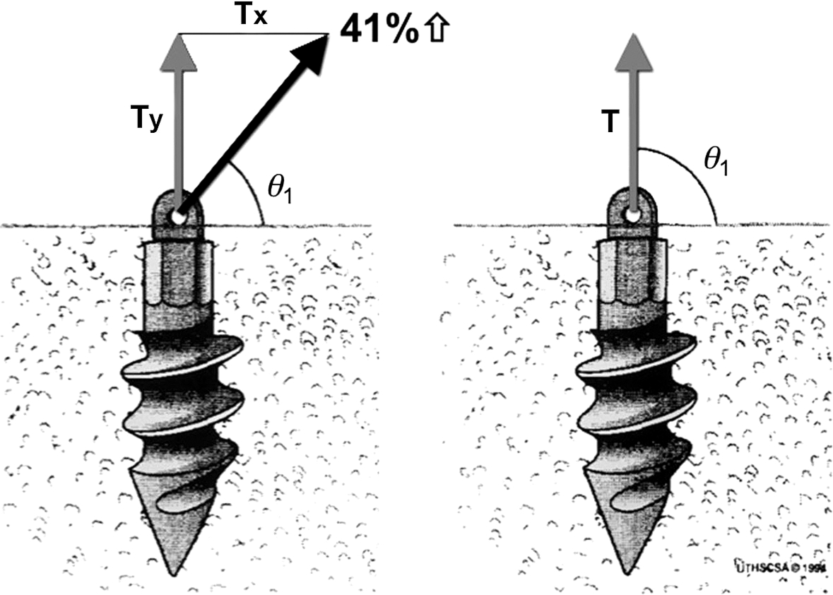
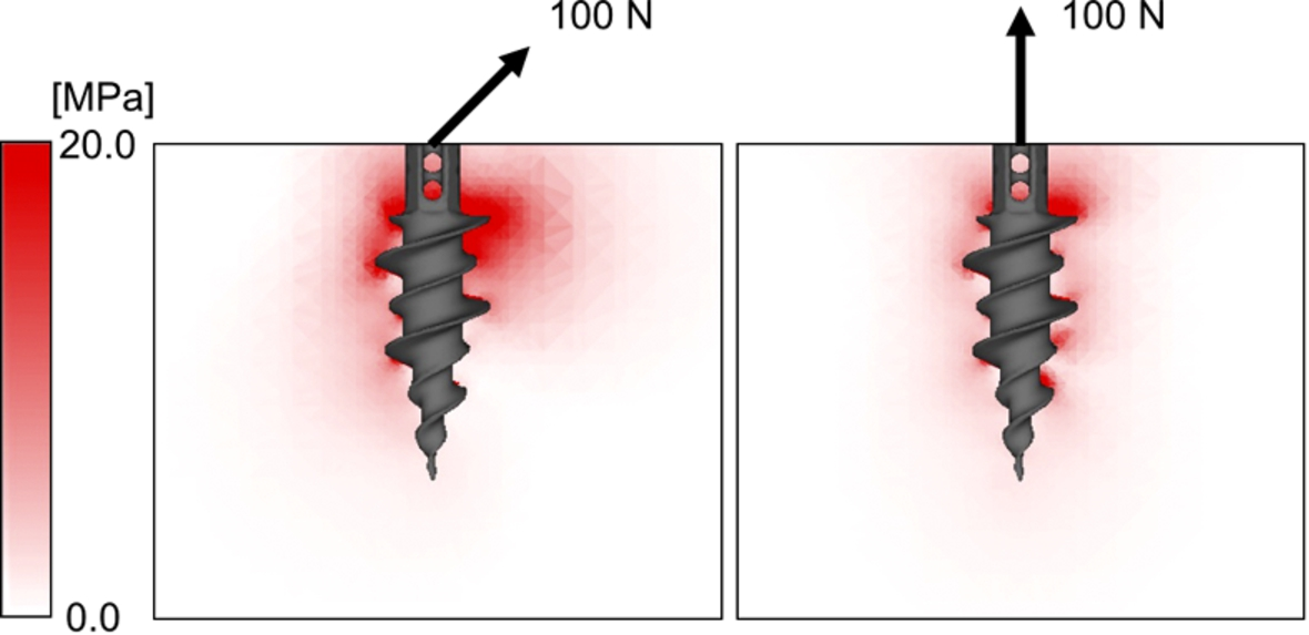
Contrary to , the description of was very limited in the original article [1]. As a result, all the biomechanical studies thereafter focused on . The previous biomechanical studies showed that the greatest pullout strength was observed when the anchor was inserted at 90° [3], 135° [5], or between 105° and 135° [4]. None of the studies showed that the pullout strength of the anchor inserted at 45° showed the greatest strength. When we try to pull out a tent peg that has been inserted into the ground, we pull it along the same line of insertion. This is because we all know that 100% of our force is used to pull out the peg if we pull it in the same direction of insertion. If we pull the 45° tent peg in 135° direction (perpendicular to the peg), we have to break the ground to pull it out, which needs far greater strength than pulling it in 45° direction (same direction of insertion). When comparing the pullout strength of a vertically inserted anchor (90° anchor) pulled either vertically (90° direction) or obliquely (135° direction), the pullout strength in the direction of 135° requires 41% more force than that in the direction of 90° to create the same amount of vertical force component based on the trigonometric function as explained in Burkhart’s article (Fig. 5). This is based on the assumption that the bone does not deform and the anchor comes out along the line of insertion; however, this is not what happens in reality. If an anchor inserted perpendicular to the bone is pulled in the 135° direction, the anchor starts to break the bone on the side of the pull, rotates inside the bone, and comes out in the direction of the pull [6]. A previous finite element model analysis has shown that the greatest amount of stress concentration is observed on the pulling side of the proximal anchor, which would break the bone and make the anchor rotate (Fig. 6) [6]. Another pullout test showed the same results: the suture anchors were pulled perpendicularly (90° pull; ) and obliquely (135° pull; ) using polyurethane foam block with various densities (Sawbones Laminated Test Blocks, Solid Rigid Type, Pacific Research Laboratories, Vashon, WA) [7]. With the low-density block, the 135° pull () (mean ± standard deviation) showed the pullout strength as 22% greater than the 90° pull (), which was almost one half the theoretical value of 41%. With the medium-density block, the 135° pull () required only 12% more force than the 90° pull (). With the high-density bone, the result became opposite to the trigonometric calculation: the 135° pull () required 19% less force compared to the 90° pull (). Using the greater tuberosity of porcine bone, the 135° pull (; ) required 7% less force than the 90° pull (; ) [15]. From these studies, it is obvious that the direction of pull affects the pullout strength, but it depends on the quality and strength of the bone. The trigonometric calculation is not always applicable in vivo setup because of bone deformation (Explanation #1).
Inclination of the pull. When you pull the anchor obliquely (), you need 41% more force than pulling it vertically. (Modified from Burkhart, 1995) [1].
Distribution of von Mises stress around the threaded anchor. When the anchor is pulled in-line with its insertion, a 100-N force creates a relatively small amount of stress concentration around the anchor. When it is pulled obliquely in the direction of 135° (), a much greater amount of stress concentration is observed at the proximal portion of the anchor eccentrically on the pulling side. (Modified from Sano et al. 2013) [6].
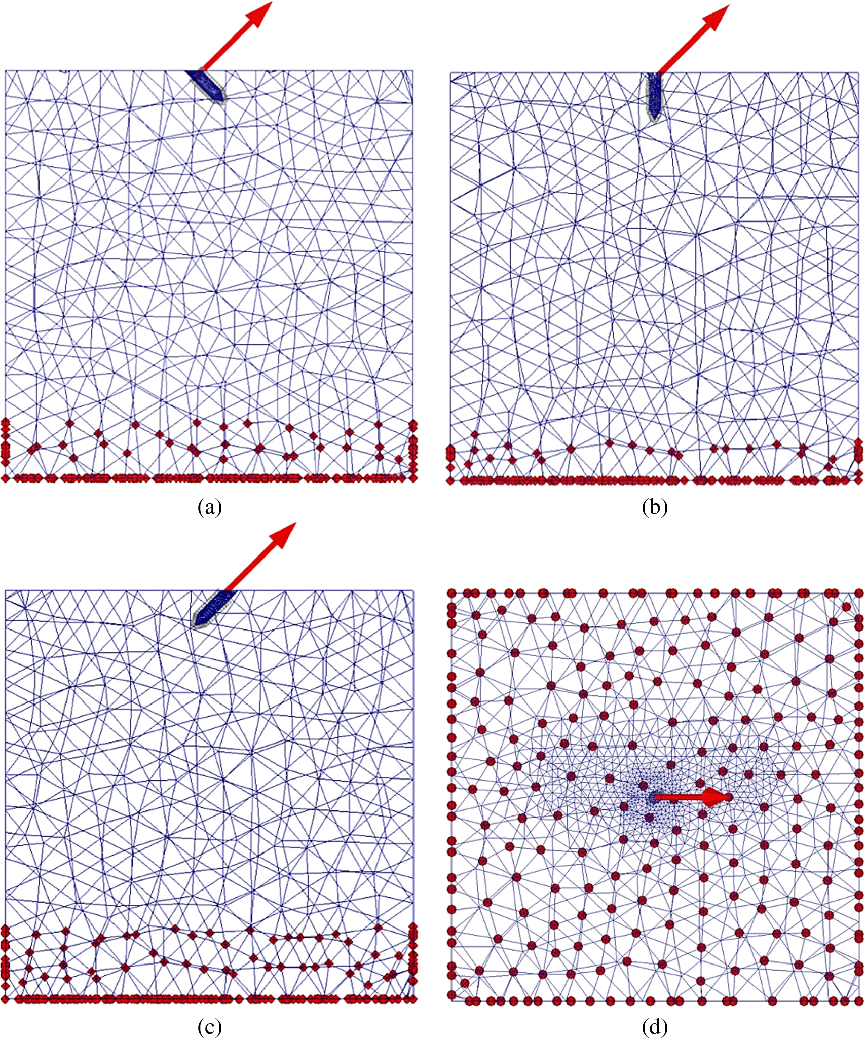
Mesh division and boundary condition of each model. The red arrow indicates the direction of tensile load applied to the inserted peg (always in the direction of 135°). The red dots show the constrained nodes to all directions during the analysis. (a) Lateral view of the model with the peg inserted at 45° (). (b) Lateral view of the model with the peg inserted at 90° (). (c) Lateral view of the model with the peg inserted at 135° (). (d) Top view of the model with the peg inserted at 90° ().
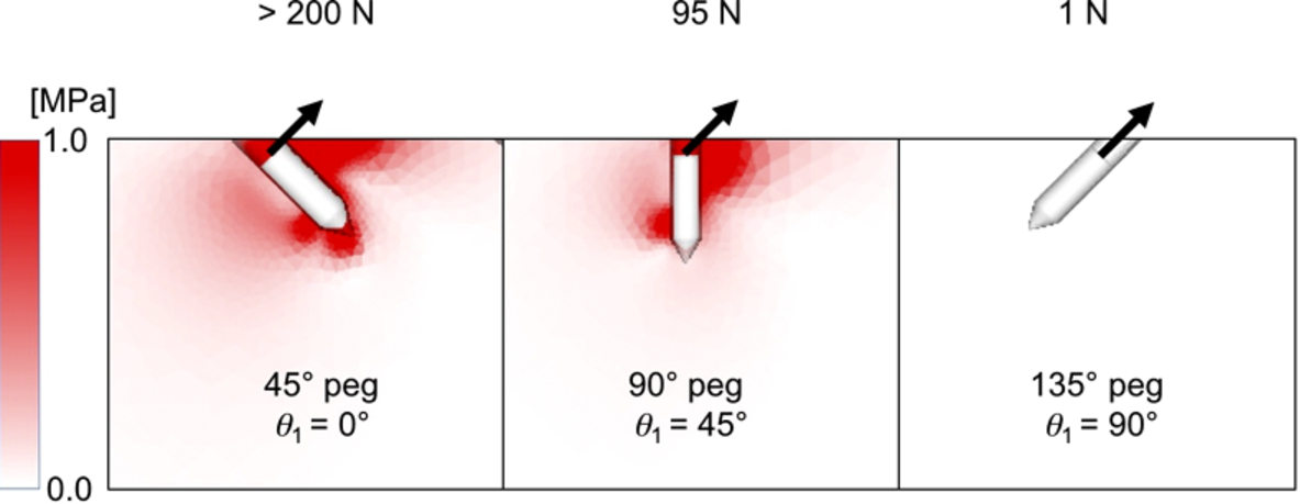
The next issue to be considered is the inclination of the anchor. When we insert a tent peg into the ground, we insert it obliquely so that the pull by the tent rope would be close to perpendicular to the tent peg. We do this because we intuitively know that the perpendicular pull of the tent peg would be most resistive to the pull by the rope. We verified this using the following finite element model analysis and biomechanical pullout test. First, we created a finite element model simulating a tent peg (thread-less anchor) inserted at three different angles (45°, 90°, and 135°) into the ground (bone). Each model consisted of the first-order tetrahedral elements in the present study (Fig. 7). The number of nodes and elements in each model are shown in Table 1. The material properties of bone and anchor were determined based on our previous study: the Young’s modulus and Poisson’s ratio were set at 1380 MPa and 0.30 for the bone and 110 GPa and 0.28 for the anchor, respectively [6]. Regarding the material failure, we hypothesized that an element crack in tension would occur when the maximum principal stress exceeded the element ultimate stress. Yield in compression was defined as occurring when the von Mises equivalent stress exceeded the element yield stress. Element failure during compression was defined as occurring when the negative value of the maximum principal strain exceeded a microstrain of 10,000 [16]. Elastic analysis was performed, and the distribution of the von Mises equivalent stress was calculated and compared among the three different angles of insertion (Fig. 8). The greatest pullout strength (>200 N) was observed when the peg was inserted at 45°, followed by the peg at 90° (95 N), and then the peg at 135° (1 N). These data perfectly matched our expectation. Next, we performed the pullout strength test using a thread-less anchor (ground the threads off the TwinFix 5.0 Ti, Smith & Nephew, Andover, MA). This thread-less anchor was inserted at three different inclinations (45°, 90°, and 135°) into a 2.0-mm drill hole created in the medium-density polyurethane foam (Sawbones, Pacific Research Laboratories, Vashon, WA) (Table 2). The pullout strength of the 45° anchor () was significantly greater than those of the 90° anchor () () and the 135° anchor () (), and that of the 90° anchor was significantly greater than that of the 135° anchor (). Using a larger drill hole of 2.5 mm with less friction between the anchor and the artificial bone, the pullout strength of the 45° anchor () was significantly greater than those of the 90° anchor () () and the 135° anchor () (), and that of the 90° anchor was significantly greater than that of the 135° anchor () (Table 2). The pullout strength of the 45° anchor was 115% that of the 90° and 175% that of the 135° anchor with use of a 2.0-mm drill hole, and 166% and 273% with use of a 2.5-mm drill hole: the pullout strengths of the 45° anchor relative to the 90° and 135° anchors were significantly greater with a 2.5-mm drill hole than with a 2.0-mm drill hole (, , respectively). The smaller the friction, the greater the advantage of inserting the anchor at 45° over 90° or 135°. These pullout tests and finite element model analyses demonstrated that an insertion angle of 45° was the best for a thread-less anchor (Explanation #2).
Details of the finite element models
Model
Number of nodes
Number of elements
45°
29,131
163,496
90°
22,294
127,078
135°
31,453
180,980
Distribution of von Mises stress around the peg. The greatest pullout strength (>200 N) was observed when the peg was inserted at 45°, followed by the peg at 90° (95 N), and then the peg at 135° (1 N). The tensile load was always applied in the direction of 135°.
Pullout strength of thread-less anchor
Insertion angle
Pullout strength (2.0-mm drill hole)
Pullout strength (2.5-mm drill hole)
45°
90°
135°
A–B: , A–C: , B–C: , D–E: , D–F: , E–F: .
The values are the mean ± standard deviation.
On the other hand, the previous biomechanical studies using threaded anchors revealed that the pullout strength was the greatest when the anchor was inserted at angles other than 45° [3–5]. Burkhart criticized these biomechanical studies, saying that the location of the suture anchor with the eyelet out of the bone should have created a greater torque to the anchor and have affected their outcome [11,12]. He also pointed out that it was essential to achieve an intra-cortical fixation of the anchor [9,12]. We performed a third biomechanical study with these two points taken into consideration. We used the laminated polyurethane foam, which was a combination of solid rigid polyurethane foam with a density of 5 pcf = 0.08 g/cm3 (low density) and 10 pcf = 0.16 g/cm3 (medium density) simulating an osteoporotic and the medium-density cancellous bone and a 2-mm e-glass-filled epoxy sheet with a density of 102 pcf = 1.63 g/cm3 simulating the cortical bone (Sawbones Laminated Test Blocks, Solid Rigid Type, Pacific Research Laboratories, Vashon, WA). The suture anchors (TwinFix 5.0 Ti, Smith & Nephew, Andover, MA) were completely inserted into this artificial bone at 45°, 90°, and 135°. The anchors were pulled in the direction of 135°, and 6 pullout tests were performed under each condition. Using the low-density bone, the pullout strength of the 90° anchor was significantly greater than those of the 45° anchor () and the 135° anchor (), but no significant difference between the 45° anchor and the 135° anchor () (Table 3). Using the medium-density bone, the pullout strength of the 90° anchor was significantly greater than those of the 45° anchor () and the 135° anchor (), and that of the 135° anchor was significantly greater than that of the 45° anchor () (Table 3). These biomechanical studies clearly showed that with a great amount of friction like a threaded suture anchor, the anchor inserted at 90° () showed the greatest pullout strength and the anchor inserted at 45° () showed the smallest pullout strength when pulled in the direction of 135°. The same results were reported when tested using human cadaveric humeri [3]. These results also satisfy the condition that should be equal to or less than 45° in the deadman theory, but does not support the interpretation that an anchor should be inserted at 45°. This discrepancy seems to come from the process of interpretation. The interpretation is that a 45° anchor would theoretically show the greatest pullout strength when pulled perpendicularly to the line of insertion (135° pull). Again, this process is based on the theoretical consideration, but in reality, the bone deforms and the anchor rotates in the bone, which causes different results from the theoretical calculation. Therefore, we can say that is true, but it is not equivalent to inserting an anchor at 45° () (Explanation #3).
Pullout strength of threaded anchors
Insertion angle
Pullout strength (low-density bone)
Pullout strength (medium-density bone)
45°
90°
135°
A–B: , B–C: , A–C: , D–E: , E–F: , D–F: .
The values are the mean ± standard deviation.
Clinical application
The original definition of the deadman theory is both and . This theory by this definition is true. However, if we interpret the deadman theory as inserting the anchor at 45°, this interpretation is not always true: it is true only when the friction at the bone–anchor interface is very small. We need to clearly understand the difference between and inserting the anchor at 45°.
As we demonstrated above, depends on the friction of the anchor–bone interface and the strength of the bone. Using the threaded suture anchors, a 90° insertion is shown to be the most resistive to the pullout force in the direction of 135°, which simulated the pull by the suture passed through the rotator cuff tendon. In the clinical setting, a suture anchor should, therefore, be inserted perpendicular to the bony surface. For medial row anchors during rotator cuff repair, it may not be easy to do so because of the acromion. In that case, bringing the arm into full adduction is recommended such that the anchor be inserted as close to the 90° direction as possible. For the lateral-row anchors on the facet or footprint anchors on the lateral cortex of the greater tuberosity, it can be inserted perpendicular to the bony surface without any difficulties.
is related to the inclination of the sutures through the rotator cuff tendon. Once the sutures are passed through the tendon and tied securely, the tendon may retract a little until the force balance reaches equilibrium. The thicknesses of the supraspinatus and infraspinatus tendons are less than 1 cm [17]. A suture is passed through the tendon almost perpendicularly with use of a biting-type suture passer, and obliquely with use of a needle type suture passer. In either case, by tying the knot securely, the tendon thickness would be decreased and the length of the suture inside the tendon would also be decreased. With such a short length of the suture, the tendon retraction caused by the inclination of the suture seems to be very small and insignificant. Thus, is most likely to be ignored during surgery because the intratendinous suture length is too short after being securely tied to affect the retraction of the tendon.
There are several limitations in this study. The finite element model analysis depends on the material properties of the structures tested. There is a limitation to simulate the exact material properties of the bone. Also, the pullout test was performed with a thread-less anchor inserted into the polyurethane foam, which is uniform in quality and widely accepted as a model for pullout test, but it may be different from the in vivo bone. We tested in three different angles (45°, 90°, and 135°) with one fixed pulling direction (135°) for the purpose of simplicity, but other insertion angles and pulling angles may show some other data.
Conclusions
Insertion angle of 45° is the strongest for a thread-less anchor, but 90° is the strongest for a threaded anchor. The pullout strength depends on the inclination of the anchor, friction of the anchor–bone interface, and quality of the bone.
Conflict of interest
The authors have no conflict of interest to report.
References
1.
BurkhartS.S., The deadman theory of suture anchors: Observations along a South Texas fence line, Arthroscopy: The Journal of Arthroscopic & Related Surgery: Official Publication of the Arthroscopy Association of North America and the International Arthroscopy Association11 (1995), 119–123.
2.
LiporaceF.A.BonoC.M.CarusoS.A.WeinerB.PennyK.FeldmanA.J.GrossmanM.G. and HaherT.R., The mechanical effects of suture anchor insertion angle for rotator cuff repair, Orthopedics25 (2002), 399–402.
3.
StraussE.FrankD.KubiakE.KummerF. and RokitoA., The effect of the angle of suture anchor insertion on fixation failure at the tendon–suture interface after rotator cuff repair: Deadman’s angle revisited, Arthroscopy: The Journal of Arthroscopic & Related Surgery: Official Publication of the Arthroscopy Association of North America and the International Arthroscopy Association25 (2009), 597–602.
4.
ClevengerT.A.BeebeM.J.StraussE.J. and KubiakE.N., The effect of insertion angle on the pullout strength of threaded suture anchors: A validation of the deadman theory, Arthroscopy: The Journal of Arthroscopic & Related Surgery: Official Publication of the Arthroscopy Association of North America and the International Arthroscopy Association30 (2014), 900–905.
5.
GreenR.N.DonaldsonO.W.DafyddM.EvansS.L. and KulkarniR., Biomechanical study: Determining the optimum insertion angle for screw-in suture anchors – Is deadman’s angle correct?, Arthroscopy: The Journal of Arthroscopic & Related Surgery: Official Publication of the Arthroscopy Association of North America and the International Arthroscopy Association30 (2014), 1535–1539.
6.
SanoH.TakahashiA.ChibaD.HattaT.YamamotoN. and ItoiE., Stress distribution inside bone after suture anchor insertion: Simulation using a three-dimensional finite element method, Knee Surgery, Sports Traumatology, Arthroscopy: Official Journal of the ESSKA21 (2013), 1777–1782.
7.
NagamotoH.YamamotoN.KurokawaD.TakahashiH.SanoH. and ItoiE., Is deadman’s angle really advantageous in suture anchor insertion? A biomechanical study, in: 60th Annual Meeting of ORS, New Orleans, March 15–18, 2014.
8.
ReedS.C.GlossopN. and Ogilvie-HarrisD.J., Full-thickness rotator cuff tears. A biomechanical comparison of suture versus bone anchor techniques, The American Journal of Sports Medicine24 (1996), 46–48. doi:10.1177/036354659602400108.
9.
BurkhartS.S., Suture anchor insertion angle and the deadman theory, Arthroscopy: The Journal of Arthroscopic & Related Surgery: Official Publication of the Arthroscopy Association of North America and the International Arthroscopy Association25 (2009), 1365; author’s reply 1365–1366.
10.
KummerF., Suture anchor insertion angle and the deadman theory. Author’s reply, Arthroscopy: The Journal of Arthroscopic & Related Surgery: Official Publication of the Arthroscopy Association of North America and the International Arthroscopy Association25 (2009), 1365–1366.
11.
BurkhartS.S., The deadman theory is alive and well, Arthroscopy: The Journal of Arthroscopic & Related Surgery: Official Publication of the Arthroscopy Association of North America and the International Arthroscopy Association30 (2014), 1049–1050.
12.
BurkhartS.S., Can the deadman be killed?, Arthroscopy: The Journal of Arthroscopic & Related Surgery: Official Publication of the Arthroscopy Association of North America and the International Arthroscopy Association31 (2015), 181–182.
13.
GreenR.N.DonaldsonO.W.EvansS.L. and KulkarniR., Author’s reply: The “deadman” concept in practice: Should we believe a mathematical theory or accept the experimental evidence?, Arthroscopy: The Journal of Arthroscopic & Related Surgery: Official Publication of the Arthroscopy Association of North America and the International Arthroscopy Association31 (2015), 182–183.
14.
RossiM.J.BrandJ.C.ProvencherM.T. and LubowitzJ.H., A cavalcade of shoulder controversies: Deadman angle revisited… divergent anchor angles and depths, and rotator cuff vectors confuse comparison… and more, Arthroscopy: The Journal of Arthroscopic & Related Surgery: Official Publication of the Arthroscopy Association of North America and the International Arthroscopy Association30 (2014), 1529–1532.
15.
NagamotoH.ShiotaY.KawakamiJ.MinetaM.ItoiE.SanoH.TakahashiH. and KurokawaD., Is suture anchor insertion of 45 degrees appropriate?, in: 41st Annual Meeting, Japan Shoulder Society, Saga, October 24–25, 2014.
16.
SanoH.ImagawaK.YamamotoN.OzawaH.YokoboriA.T. and ItoiE., Predicting failures of suture anchors used for rotator cuff repair: A CT-based 3-dimensional finite element analysis, Bio-Medical Materials and Engineering25 (2015), 371–380. doi:10.3233/BME-151535.
17.
TuohetiY.ItoiE.MinagawaH.WakabayashiI.KobayashiM.OkadaK. and ShimadaY., Quantitative assessment of thinning of the subscapularis tendon in recurrent anterior dislocation of the shoulder by use of magnetic resonance imaging, Journal of Shoulder and Elbow Surgery/American Shoulder and Elbow Surgeons… [et al.]14 (2005), 11–15. doi:10.1016/j.jse.2004.04.009.