
Abstract
BACKGROUND:
Inertial measurement unit (IMU)-based motion sensors are affordable, and their use is appropriate for rehabilitation. However, regarding the accuracy of estimated angle information obtained from this sensor, it is reported that it is likely affected by velocity.
OBJECTIVE:
The present study investigated the reliability and validity of the angle information obtained using IMU-based sensors compared with a three-dimensional (3D) motion analyzer.
METHODS:
The Euler angle obtained using the 3D motion analyzer and the angle obtained using the IMU-based sensor (IMU angle) were compared. Reliability was assessed by comparing the Bland–Altman analysis, intra-class correlation coefficient (ICC) (1,1), and cross-correlation function. The root mean square (RMS) error, ICC (2,1), and cross-correlation function were used to compare data on the Euler and IMU angles to evaluate the validity.
RESULTS:
Regarding reliability, the Bland–Atman analysis indicated no fixed or proportional bias in the angle measurements. The measurement errors ranged from 0.2° to 3.2°. In the validity, the RMS error ranged from 0.3° to 2.2°. The ICCs (2,1) were 0.9. The cross-correlation functions were >0.9, which indicated a high degree of agreement.
CONCLUSION:
The IMU-based sensor had a high reliability and validity. The IMU angle may be used in rehabilitation.
Introduction
Quantitative evaluation of human movement during rehabilitation is essential for gaining insight into the structure of disability and facilitating the development of appropriate therapeutic strategies. Various measurement equipment, such as optoelectronic systems, electromagnetic systems, image processing systems, and inertial measurement units (IMU), have been developed to quantify human motion on the skin [1]. Motion capture systems can be classified into marker-based and marker-less systems, with optoelectronic systems considered the gold standard for quantitative evaluation of human motion on skin, belonging to the marker-base group [2–4]. These systems have the advantage of recording the spatiotemporal parameters of various motion tasks with high accuracy; however, they are associated with several disadvantages, such as the need for a dedicated space (e.g., laboratory) and high associated costs, which prevent wider adoption in clinical practice [5–10].
In contrast, wearable sensors, such as IMU, represent a promising form of marker-less motion capture [3,11–14] by recording acceleration, angular velocity, and geomagnetism along three axes [10,15]. Compared to optoelectronic systems, IMU-based sensors offer several clear advantages, including affordability, low weight, and versatility in placement, thereby leading to broader adoption in rehabilitation settings [16]. However, obtaining direct angle information from IMUs has proven challenging and typically necessitates the integration of angular velocity [17,18]. However, it tends to be less reliable due to the drift effect, although, various algorithms have been developed to minimize this [19–21]. Moreover, geomagnetism facilitates sensor orientation along the global coordinates [22]. Sensor fusion through the combination of acceleration, angular velocity, and geomagnetic data has improved data reliability [23], although its limitations have prevented widespread use in rehabilitation [24].
Although IMU-based sensors capable of calculating quaternions from tri-axial data and estimating angles have been developed recently [15], these estimates remain susceptible to influences from the underlying acceleration and angular velocity measurements, thereby affecting accuracy [15,25]. Therefore, before considering these systems as evaluation tools for rehabilitation, examining these influences using appropriate engineering methods is essential.
Therefore, the current study aimed to evaluate the reliability and validity of the estimated angles of IMU-based sensors by comparing them with the Euler angles obtained from a three-dimensional (3D) motion analyzer.
Methods
Measuring equipment
Direct current-drive motors
Two types of direct current (DC)-drive motors were used to produce a 5-rpm motor (Uxcell) and a 100-rpm motor (Jieotwice), both of which could be adjusted up to 12 V (Fig. 1a). A variable-voltage alternating-current (AC)–DC converter (Zerodis) was used to rotate the motors (Fig. 1b).
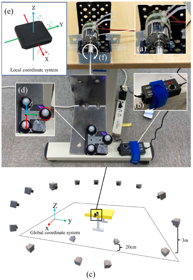
Uniform circular motion system using a DC drive motor. a: DC drive motors (5 and 100 rpm). b: The variable-voltage AC–DC converter. c: Measurement environment. d: A reflective marker affixed to the IMU-based sensor. e: The IMU-based sensor. f: Direction of rotation for the DC drive motor. AC, alternating-current; DC, direct current; IMU, inertial measurement unit.
VICON MX-T (Vicon Motion Systems Ltd, Oxford, UK), a 3D motion analyzer comprising 16 cameras, was used (Fig. 1a). The sampling frequency was 100 Hz.
IMU-based sensor
One Leomo system (TYPE-s, Leomo, Tokyo, Japan) (size: 37 mm (W) × 37 mm (D) × 7.8 mm (H), weight: 12 g) (Tokyo, Japan) was used in the study. The IMU-based sensor can measure three-axis acceleration, angular velocity, and quaternion. The angle directly obtained from the IMU-based sensor is the X-axis rotation information. The sampling frequency was 100 Hz.
Tasks
The rotational speeds of the DC drive motors were set to 4, 8, and 12 V, respectively, for 5- and 100-rpm motors using a variable-voltage AC–DC converter. The measurements for each voltage on both motors for 30 measurements were taken five times (5 rpm, 100 rpm × voltage (4 V, 8 V, and 12 V) × five times).
Measurement procedure
A workbench was placed at the center of the measurement space, and a DC drive motor was installed on the workbench. The workbench was leveled with a leveler to ensure that it was horizontal. The infrared cameras were positioned 3 m from the floor, 360° around the workbench. In total, 2 of 16 cameras were placed 20 cm from the floor to capture the markers from below (Fig.1c).
The IMU-based sensor was set up by fixing a T-shaped stainless-steel plate (48 mm [W] × 40 mm [H]) with a double-sided tape. Thus, its long axis was aligned with the X-axis of the IMU-based sensor’s local coordinates (Fig. 1c). Next, the IMU-based sensor was fixed to an L-shaped stainless-steel plate with double-sided tape. Therefore, its local coordinate system could match the global coordinate system (Fig. 1d). The DC drive motor and the L-shaped stainless-steel plate were connected with shaft joints at both ends of the stainless-steel plate. The DC drive motor rotated to the right (X-axis rotation) when viewed from the shaft end (Fig.1f).
Analytical method
The analyzed angles used were the Euler angle (angle of continuous rotation around the X, Y , and Z axes) from the 3D motion analyzer and the estimated angle (IMU angle) calculated from the quaternion of X-axis rotation from the IMU-based sensor. The analysis items were angular velocity, angular change, and time-series waveform of the angle. A 6-Hz low-pass filter (Butterworth filter) was used.
The motion start rule of the 3D motion analyzer was defined as the time when the infrared marker circled in red, as shown in Fig. 1d, deviated from the average Z-axis coordinate value for 1 s before the start of motion, plus three times the standard deviation (Fig. 2a) [26]. The data analysis range was defined as one cycle until the infrared marker coordinate values again reached the values at the start of motion (Fig.2a).
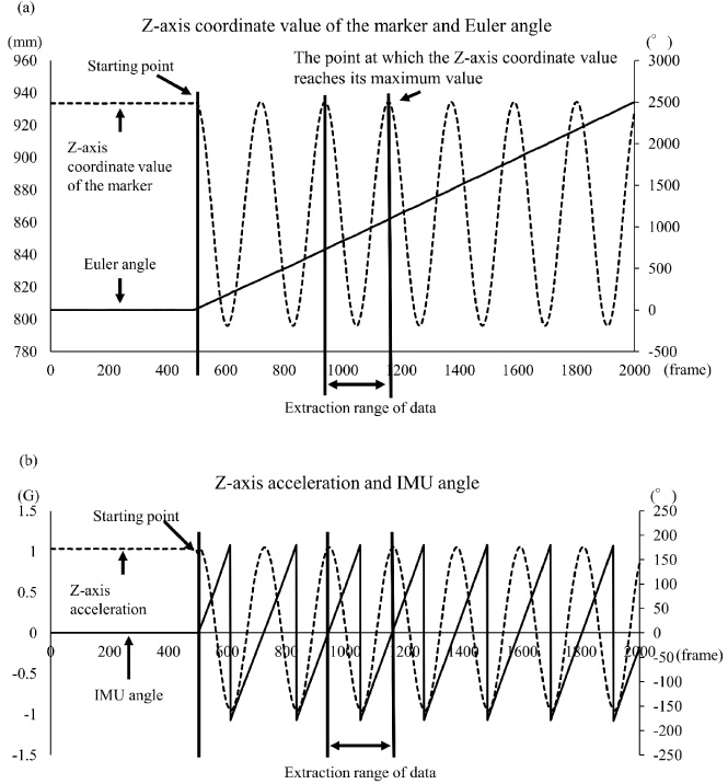
Analysis procedure of the Euler and IMU angle for uniform circular motion. (a) Z-axis coordinate values (dotted lines) of the marker and Euler angles (solid lines), as obtained from the three-dimensional motion analysis system. The horizontal, left vertical and right vertical axes represent the frame number, Z-axis coordinate values of the markers, and accumulated angles, respectively. (b) Z-axis acceleration values (dotted lines) and IMU angles (solid lines), as obtained from the motion sensor shown in Fig. 1d. The horizontal, left vertical and right vertical axes represent the frame number, Z-axis acceleration values and angles, respectively. In the case of a right rotation, the IMU angle outputs a range of 0°–−180° from its initial position, followed by a range of 180°–0°, thereby completing a full rotation of 360°. IMU, inertial measurement unit.
The motion start rule of the IMU-based sensor was defined as the time when the mean value of the Z-axis acceleration obtained from the IMU-based sensor before the motion started, plus three times the standard deviation, deviated from it (Fig. 2b) [26]. The data analysis range was defined as one cycle until the acceleration value of the IMU-based sensor again reached the value at the start of the exercise (Fig. 2b). The range of motion (ROM) was defined as the change from the start position (0°) at the end of the exercise. The analysis range of the time-series waveforms of the angles was one cycle from the start to the end of the IMU-based sensor motion.
The R statistical software was used (4,2,1).
Reliability
Bland–Altman analysis, intra-class correlation coefficient (ICC) (1,1), and cross-correlation function (CCF) were used to compare the first and second MS angle data obtained from the IMU-based sensor. Bland—Altman analysis was used to assess absolute reliability to determine the presence of fixed or proportional bias in the angular change of the IMU angle obtained from the first and second measurements. After confirming the absence of error, the measurement error was calculated. The agreement between the angular change of the IMU angle obtained from the first and second measurements was assessed using ICC (1,1) as a measure of relative reliability; CCF was used to examine the agreement between the time-series waveforms of the IMU angle obtained from the first and second measurements. The strength of agreement in ICC was defined as follows: 0.81–1.0, almost perfect; 0.61–0.80, standard; 0.41–0.60, moderate; 0.21–0.40 fair; and 0.0–0.20, slight [27].
Validity
Data on the Euler and IMU angles were compared to examine validity using the root mean square error (RMSE), ICC (2,1), and CCF. In RMSE, the error in the angular change in the IMU and Euler angles was calculated. In ICC (2,1), the degree of agreement between the angular changes in the Euler and IMU angles was examined. The degree of agreement between the time-series waveforms of the Euler and IMU angles was assessed in CCF.
Results
Angular velocity of the 5- and 100-rpm motors
Table 1 shows the angular velocities of the 5- and 100-rpm motors; the 5 rpm motor at 4 V was the slowest, and the 100-rpm motor at 12 V was the fastest.
Angular velocity for uniform circular motion
Angular velocity for uniform circular motion
rpm, rotations per minute; SD, standard deviation.
ROM
Bland–Altman analysis showed no fixed or proportional bias for either the 5- or 100-rpm motors. The measurement errors were the smallest at 4 and 8 V for the 5-rpm motor and the largest at 12 V for the 100-rpm motor (Table 2). Since fixed and proportional errors were not observed, reliability was examined at ICC (1,1). However, all measurements showed low values (Table 3).
Bland–Altman analysis of ROM for uniform circular motion
Bland–Altman analysis of ROM for uniform circular motion
ROM, range of motion; rpm, rotations per minute.
ICC of ROM for uniform circular motion
ICC, intraclass correlation coefficient; ROM, range of motion; rpm, rotations per minute; CI, confidence interval.
The agreement between the time-series waveforms of the first and second measurements of the IMU angle for each motor was high at 0.99 (Table 4).
Reliability of the waveform for uniform circular motion
Reliability of the waveform for uniform circular motion
rpm, rotations per minute; CCF, cross-correlation function.
ROM
The ICC (2,1) showed a high degree of agreement, >0.9 for all measurements. The RMSE ranged from 0.1° to 2.2° (Table 5).
Validity of ROM for uniform circular motion
Validity of ROM for uniform circular motion
ROM, range of motion; rpm, rotations per minute; ICC, intraclass correlation coefficient; CI, confidence interval; RMSE, root mean squared error.
The agreement between the time-series waveforms of the Euler and IMU angles for each motor was high at 0.99 (Table 6).
Validity of the waveform for uniform circular motion
Validity of the waveform for uniform circular motion
rpm, rotations per minute; CCF, cross-correlation function.
The present study aimed to examine the absolute reliability and validity of the IMU-based sensor for accurately measuring X-axis rotation using a DC drive motor. The results showed that the absolute reliability and validity were high, while the relative reliability was low. Moreover, the time-series waveform agreement was high for both reliability and validity.
The Bland–Altman analysis [28,29] was used to examine the absolute reliability of the estimated angle obtained from the IMU-based sensor, and the results showed that neither fixed nor proportional biases were present. The measured values obtained from instruments include the true values errors that can be classified as systematic biases or random errors. The systematics error can further be classified into fixed and proportional biases, wherein systematics error includes errors that occur in a specific direction regardless of the true value, and random errors include errors that increase in proportion to the magnitude of the true value. As systematic biases were not observed in the current findings, consideration of the influence of random errors, including individual (i.e., biological) differences and measurement errors, was essential. However, the influence of individual differences was likely to be minor in the current study due to the use of motors, and, therefore, the influence of measurement error was examined and found to be a maximum of 3.2°. Evaluations using a goniometer routinely used to measure human joint angles, typically standardize measurements into 5° increments [30], and any values less than this are considered errors. Therefore, the current study’s findings were considered to be within the acceptable range for use in rehabilitation. Thus, the relative reliability was validated using ICC (1,1). However, the ICC of all measurements was low (Table 3). Sample-to-sample and measurement-to-measurement variability and error are used to calculate the ICC (1,1) [31]. Therefore, the ICCs (1,1) are affected by sample-to-sample variation and measurement-to-measurement variation [32]; however, the measurement-to-measurement variation was extremely minimal. Hence, the ICC in the current measurement results is considered low, as shown in Fig. 3. However, as depicted in Fig. 4, the 95% confidence interval of the standard error of the mean was low. As shown in Table 2, the measurement errors ranged from 0.2° to 3.2°. Thus, the accuracy of the IMU-based sensor meets a certain level. The time-series waveforms had a high degree of agreement at 0.99 for all measurements, and no effect on angular velocity was observed.
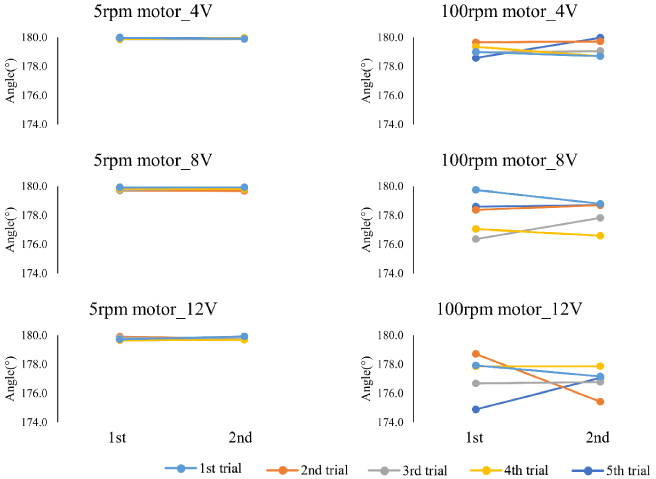
Measurement for the 5-and 100-rpm motors. The left column shows the results for the 5-rpm motor, and the right column shows the results for the 5-rpm motor. The vertical axis of each figure shows the angle. The first horizontal axis shows the results of the first measurement, and the second horizontal axis shows the results of the second measurement. rpm, rotations per minute.
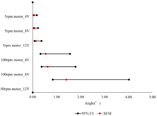
95%CI of SEM for uniform circular motion. The 95% CI of SEM for each measurement is shown. Black circles indicate the upper and lower limits of 95% CI. Red circles indicate SEM. rpm, rotations per minute; CI, confidence interval; SEM, standard error of the mean.
Next, the validity of the MS angle in constant-velocity rotational motion was examined using the Euler angle obtained using the 3D motion analyzer. The agreement between the IMU and Euler angles in the ROM was high, with an ICC (2,1) of >0.9. The errors ranged from 0.3° to 2.2°. A previous study [33] assessed the accuracy of angles obtained using IMU-based sensors. Results showed a maximum measurement error of 5.4° at an angular velocity of 180°/s and a maximum error of 11.6° at an angular velocity of 360 °/s. In another study [12], the measurement error was 0.9° at an angular velocity of 180°/s. The measurement error was 0.9° at an angular velocity of 360 °/s. The measurement error was 0.9° at an angular velocity of 180°/s. Other studies have reported measurement errors of 0.7°–1.4° for angular estimates using quaternions calculated based on information obtained from IMU-based sensors [34]. Considering that the average angular velocity of the 12-V motor with the 100-rpm motor used in this study was 608.3 °/s ± 12.2 °/s and the error at this time was 2.2°, the IMU-based sensor used in this study was highly valid. The agreement of the time-series waveforms of the IMU and Euler angles was high at >0.9 for all measurements, and there was no effect on angular velocity.
Various devices, including the IMU-based sensor used in this study, have been developed to quantitatively evaluate human movement during rehabilitation. However, the accuracy of the estimated angular information obtained using motion sensors can be influenced by movement speed [15,25], potentially depending on the specific task performed. In the field of rehabilitation, evaluations span a wide range of movements, from slow activities of daily living to rapid recreational and sport activities. In a previous study focusing on slow movements, Wang and colleagues [35] investigated the angular velocities of the trunk and lower extremity during sit-to-stand and stand-to-sit movements at different speeds. They found that during sit-to-stand movement, trunk extension had the slowest angular velocity at maximum speed of 51.8 °/s ± 11.8 °/s, while knee extension had the fastest at 172.8 °/s ± 38.1°/s. Conversely, during stand-to-sit movement, trunk flexion had the slowest angular velocity at optimal speed of 47.2 °/s ± 13.0 °/s, while knee flexion had the fastest at 149.9 °/s ± 32.8 °/s. Another study reported the angular velocities of low-extremity joints during stair climbing, in which the angular velocities of the hip and knee joints were 10 °/s and 40 °/s, respectively, during ascent and 25 °/s and 50 °/s, respectively, during descent [36]. In contrast, research focusing on rapid movements, such as the study by Mentiplay et al. [37], reported peak pre-swing ankle joint plantar flexion angular velocity of 384.05 °/s ± 45.74 °/s when walking at 1.40–1.60 m/s, while Struzik et al. [38] observed maximum knee joint angular velocity of 934.7 °/s ± 199.2 °/s when running at 28.6 ± 2.9 km/h over 30 m. Therefore, for fast movements like running, increasing the motors rotation speed further is necessary to verify the measurement accuracy. However, for evaluating daily activities like sit-to-stand, stand-to-sit, climbing stairs, and walking, the motor’s rotation speed used in this study was sufficient, and clinical application was feasible.
The present study had several limitations. That is the IMU-based sensor used only estimated angles in the X-axis. Therefore, the Y - and Z-axis rotation details were unknown, and complex motion on all three axes could not be evaluated.
This study compared the reliability and validity of the angle information obtained using an IMU-based sensor and that obtained using a 3D motion analyzer. The absolute and relative reliability of the IMU-based sensor used in this study was high.
The IMU-based sensor equipped with an inertial measurement device has few restrictions on the measurement environment and, thus, can be used in various environments. In future studies, investigating the reliability and validity of velocity-based motion measurements will be essential to advance clinical applications in rehabilitation.
Footnotes
Acknowledgements
The authors have no acknowledgements.
Conflict of interest
The authors declare that they have no conflict of interest.
Funding
The authors report no funding.