
Abstract
BACKGROUND:
The main responsibility of the anterior cruciate ligament (ACL) is to restore normal knee kinematics and kinetics. Although so far different research has been carried out to measure or quantify the stresses and strains in the ACL experimentally or numerically, there is still a paucity of knowledge in this regard under different flexion angles of the tibiofemoral knee joint.
OBJECTIVE:
Understanding the stresses and strains within the ACL under various loading and boundary conditions may have a key asset for the development of an optimal surgical treatment of ACL injury that can better restore normal knee function. This study aimed to calculate the stresses and strains within the ACL under different flexion angles using a patient-specific finite element (FE) model of the human tibiofemoral knee joint.
METHODS:
A patient-specific FE model of the human tibiofemoral knee joint was established using computed tomography/magnetic resonance imaging data to calculate the stresses and strains in the ACL under different flexion angles of 0, 10, 20, 30, and 45
RESULTS:
Although the role of the flexion angle in the induced stresses and strains of the ACL was insignificant, the highest stress and strain were observed at the flexion angle of 0
CONCLUSIONS:
The results have implications not only for understanding the stresses and strains within the ACL under different flexion angles, but also for providing preliminary data for the biomechanical and medical experts in regard of the injuries which may occur to the ACL at relatively higher flexion angles.
Introduction
The human anterior cruciate ligament (ACL) plays an essential role in maintaining knee stability in multiple directions and is one of the most frequently injured ligaments of the knee [1, 2]. Understanding the stresses and strains within the ACL of the human during knee motion is important, as the data can be used to better understand the mechanism of injury, to improve the design of ACL reconstruction procedures, to optimize rehabilitation protocols, and to provide a basis for the close examination of cellular responses to external forces [3].
Material properties and number of elements/nodes of the FE model
Material properties and number of elements/nodes of the FE model
(a) The FE model of the femur, tibia, cartilage, and anterior cruciate ligament. The force was applied to the proximal end of the femur and the distal end of the tibia was fixed in all directions. (b) The reproduced femur models at each flexion angle [20].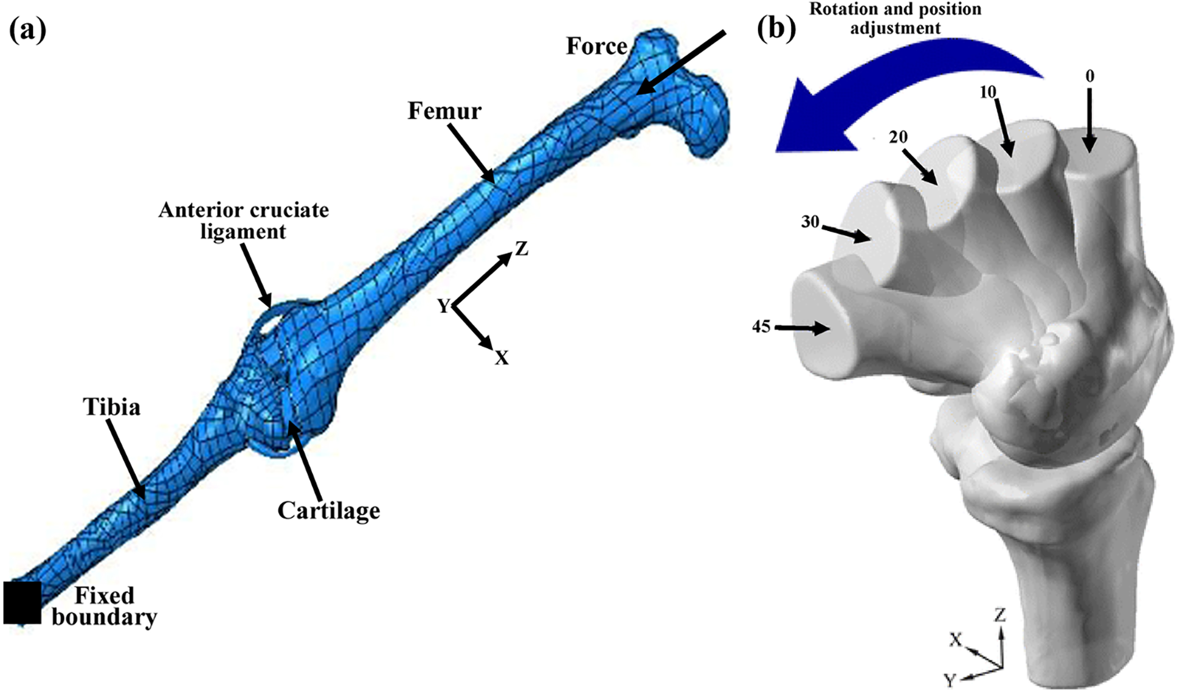
The contours of the von Mises stress under different flexion angles of (a) 0, (c) 10, (e) 20, (g) 30, and (i) 45. The contours of the strain under different flexion angles of (b) 0, (d) 10, (f) 20, (h) 30, and (j) 45.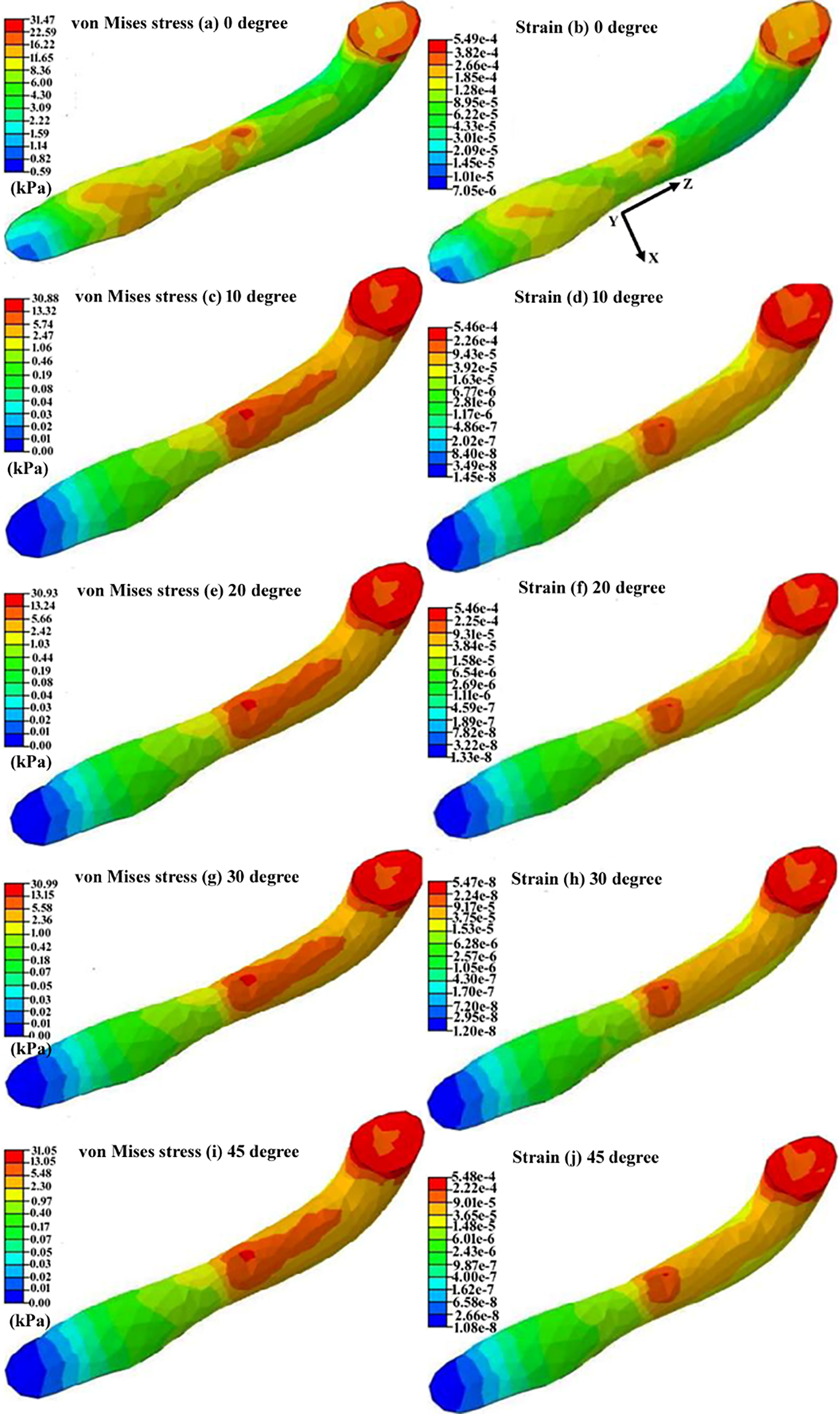
Much effort has been done to experimentally measure the stresses and strains within the ACL [4, 5, 6]. However, experimental techniques cannot determine the stresses and strains distributions within the ACL under various forces and boundary conditions. Therefore, the application of numerical techniques, especially finite element method (FEM), is preferable as they enable us to map the stresses and strains within the ACL under different flexion angles and boundary conditions. Several researchers to calculate the stresses in the ACL have used FE [7, 8, 9]. These studies utilized a patient-specific three-dimensional (3D) FE model of the ACL reconstructed from computed tomography (CT) images. Thereafter, the stresses and deformations in the ACL under various forces and boundaries were calculated and reported. A few other studies work on the mechanical properties of the ACL by itself to help predict joint kinematics and ligament forces [10, 11, 12]. Although different studies have been done so far with regard to the stress and strain as well as mechanical calculations in the ACL, there is still a lack of knowledge on the stresses and strains within the ACL of the human knee joint under different flexion angles. The knee subjects to various loading conditions on a basis of the daily activities, such as climbing the stairs, seating, standing, etc. These movements apply forces at different directions to the ACL, which cannot be quantified experimentally. Experimental measurement has been limited in conducting parametric studies of the various factors in ACL injury and reconstruction. In addition, the behavior of the knee in rotations as well as other degrees of freedom could have important influences on all the aspects of knee function, such as the contact stresses of the articular joint. Therefore, this study aimed to establish a patient-specific FE model of the tibiofemoral knee joint, including the femoral and tibial bones, cartilage, and ACL, to compute the stresses and strains in the ACL under different flexion angles of 0, 10, 20, 30, and 45
The FE model of the tibiofemoral knee joint, including the femur, tibia, cartilage, and ACL, were established on the basis of the CT/MRI data as displayed in Fig. 1a. The CT/MRI images were attained from a healthy male individual with the weight and age of 80 kg and 41 years, respectively. Our institutional review board approved the experimental design prior to the study. Written informed consent was obtained from the participants and the study adhered to the Declaration of Helsinki 2008. In short, the digital imaging and communications in medicine (DICOM) images were taken using the contrast resolution of 2 mm@0.3% (Activion 16 Multislice CT, Toshiba Medical Systems Corporation, Tokyo, Japan). The images were analyzed in MIMICS software (MIMICS 10.0, Materialise Inc., Belgium) to establish a model of the tibiofemoral knee joint. The model was reconstructed and modified in Solidworks (Dassault Systèmes, Vélizy-Villacoublay, France). Thereafter, it was assembled, meshed, and solved in Abaqus (Dassault Systèmes, Vélizy-Villacoublay, France). The mechanical properties and number of elements/nodes of the FE model components are listed in Table 1.
The loading and boundary conditions of the model are indicated in Fig. 1a. Load of 400 N to represent a body weight was applied to the proximal end of the femur. The distal end of the tibia was fixed in all directions. The contact between the femur/tibia and cartilage were defined to be tied. Different flexion angles, including 0, 10, 20, 30, and 45
Results and discussions
The biomechanical functions of the knee may be affected by different parameters, the role of the ACL due to its responsibility in restoring the normal knee kinematics and kinetics is crucially important. Construction of a suitable numerical model, which can mimic the biomechanical performance of the ACL in the tibiofemoral knee joint, has a key asset as it allows us to have a parametric study on ACL injury or reconstruction. However, establishing such a model which can closely go along the clinical data under various external loads and flexion angles has always been a challenge in computational biomechanics [13, 14]. This study utilized CT/MRI data of a healthy male individual to establish a 3D FE model of the tibiofemoral knee joint (Fig. 1a), including the femoral and tibial bones, cartilage, and ACL, to compute the stresses and strains within the ACL under different flexion angles (Fig. 1b). To investigate the joint response at different flexion angles, the tibia was restrained in the anterior translation to counterbalance the extensor moment of quadriceps forces while preserving the joint flexion at a desired level [15, 16, 17]. This constraint, however, apart from generating the desired extensor moment, introduces posterior forces on the tibia, the magnitude of which depends on the distal location of restraint and the extensor moment [18]. Here, we restrained the distal end of the tibia as the fixed boundary condition throughout the simulation while changing the effective point of stress at the proximal end of the femoral bone (Fig. 1b). It has been shown that the most ACL tearing occurs near the femoral insertion site and in the mid-substance [3, 19]. Our results also showed the highest stresses and strains at the proximal end of the ACL, where it attaches to the distal end of the femoral bone (Fig. 2). The highest stress and strain values were 31.47 kPa and 5.49
Despite the advantages of using a 3D computational knee joint model, there are certain limitations in the current modeling method. It is noted that the model was validated under a 400 N load, which is lower than the physiological loading magnitudes estimated for daily activities, such as walking. Current in vitro experiments are also limited to low loading conditions. Therefore, the model needs to be further validated under physiological loading levels in order to predict knee responses during daily activities. In addition, this study could benefit from neuro-musculoskeletal multibody modeling [20, 21, 22] to add the forces acting on the tibiofemoral joints which trigger more accurate stress and strain mapping in the ACL.
Conclusions
This study aimed to calculate the stresses and strains within the ACL under different flexion angles. To do this, a patient-specific FE model of the knee joint, including the femoral and tibial bones, cartilage, and ACL, was established using CT/MRI data of a healthy male individual. The results showed an insignificant role of the flexion angle in the induced stresses and strains of the ACL. The concentrations of the stresses and strains in the ACL were in its attachment site to the distal end of the femoral bone, which the clinical studies reported as the most vulnerable site of ACL rupture.
Footnotes
Conflict of interest
None declared.