
Abstract
The minimum flexural reinforcement requirement has been used in the current bridge design specifications to protect the member from brittle failure after the formation of the first flexural cracks. Several variables have been reported to affect this requirement, such as concrete strength, amount of prestressing in the member, and type of cross section. Recently, the Precast/Prestressed Concrete Institute (PCI) developed a new type of beam section (NEXT beam) to accelerate bridge construction and enhance the sustainability of bridges. As a newly developed beam section, no research on the minimum flexural reinforcement has been reported for NEXT beam bridges. This paper aimed to examine the minimum flexural reinforcement requirements in the current AASHTO LRFD Bridge Design Specifications for NEXT beam bridges. A comprehensive parametric study was analytically conducted with various parameters, including bridge section, beam section, concrete strength, and span length. The results from this study showed that the current minimum flexural reinforcement requirements were met for all bridges examined herein; the concrete strength, beam cross section, and span length could affect the levels of safety against brittle failure after first flexural cracks for NEXT beam bridges.
Introduction
Using precast concrete elements in bridge structures could provide better durability and less construction time compared to cast-in-place (CIP) concrete [e.g., 1, 2]. Many bridges in the US and abroad have been suffering from steel corrosion, which has caused a great number of bridges to need immediate maintenance, repair and/or strengthening. Accelerating the bridge construction speed could offer several benefits, such as reducing direct costs and indirect costs associated with the environmental, social, and economic impacts due to traffic delays [3]. To date, several different types of prestressed precast concrete beams have been used in bridges, e.g., I-girder, U-beam, box beam, and voided slab [4, 5]. Adjacent box beam bridges have been popularly used for medium-span bridges in the northeast US; however, several limitations were observed for this type of bridges, such as difficulty of fabrication, issues with grouting procedures during field construction, and difficulty of accommodating utility across the width of the bridge [6]. In addition, various durability problems have been identified for adjacent box beam bridges [7]. Recently, a novel beam section, called the northeast extreme tee (NEXT) beam, was developed by the Precast/Prestressed Concrete Institute (PCI), as shown in Fig. 1 [6, 8]. Table 1 shows the details of various NEXT F beam sections. Note that the minimum and maximum beam widths are 8 ft and 12 ft, respectively; the beam section is named after the beam depth, for example, NEXT 24F beam has a beam depth of 24 in (609.6 mm); currently there are four different beam depths available, i.e., 24 in (609.6 mm), 28 in (711.2 mm), 32 in (812.8 mm), and 36 in (914.4 mm) [6]. Bridges made of NEXT F beams could achieve many benefits, including ability to support utilities between beam stems, no need for intermediate diaphragms and shear keys, and no need for concrete deck formwork [6, 9]. Gardner and Hodgdon reported an example of a bridge replacement project, in which it was estimated that using NEXT beams saved about seven weeks on the erection of beam superstructure, if compared to Northeast Bulb Tee beam superstructure [9]. Figure 2 shows an example NEXT beam bridge [9].
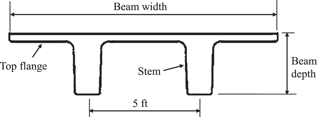
NEXT F beam cross section (Adapted from [6]; Note: 1 ft = 304.8 mm).

NEXT beam bridge in York, Maine [9] (note that this was originally published in the PCI Journal).
NEXT F beam section properties (Adapted from [6])
(Note: I = moment of inertia; Yb = distance from bottom of beam to center of gravity; 1 in = 25.4 mm).
The safe design of a prestressed concrete beam requires the member to possess sufficient strength and ductility; the minimum flexural reinforcement requirements have been used in the design codes and specifications to ensure the member will not fail in a brittle manner after the formation of the first flexural cracks [5]. The ratio of Mo/Mcr has been commonly used to ensure the safety of prestressed concrete beams with minimum flexural reinforcement, where Mo is the flexural strength at the ultimate limit state and Mcr is the moment at the first flexural cracks; the codes and specifications require Mo to be above a certain percentage of Mcr so that the member is protected from experiencing sudden failure [5]. Several variables may affect this requirement, including concrete compressive strength, concrete cracking strength, amount of prestressing in the member, use of unbonded tendons, and type of cross section [5]. A recent parametric study based on the AASHTO LRFD specifications showed that the ratio of Mo/Mcr varied from 1.2 to 1.57 for beams with different concrete strengths and cross sections (i.e., I-girder, U-beam, box beam, voided slab, spliced girder, segmental) [5]. It is worth noting that the NEXT beam sections were newly developed and no research on the minimum flexural reinforcement has been reported. Therefore, this paper aimed to examine the minimum flexural reinforcement requirements in the current AASHTO Design Specifications [4] for NEXT beam bridges. A comprehensive parametric study was conducted with various parameters, including bridge section, beam section, concrete strength, and span length. The results from this study showed the effects of different parameters on the level of safety against brittle failure after first flexural cracks for NEXT beam bridges. The research findings shed light on the design of NEXT beam bridges for bridge engineers.
Scope of work
In this paper, two different bridge sections (i.e., I, II) were examined: bridge section I is made with four 8 ft wide NEXT beams, while bridge section II is made with four 12 ft wide NEXT beams, as shown in Fig. 3. For each bridge section, four beam sections (i.e., NEXT 24, NEXT 28, NEXT 32, and NEXT 36) were explored; for each beam section, two different span lengths were examined. For each case, three different concrete strengths were investigated. Thus, a total of 48 NEXT F beam bridges (non-skewed) were analytically examined herein, as shown in Table 2.
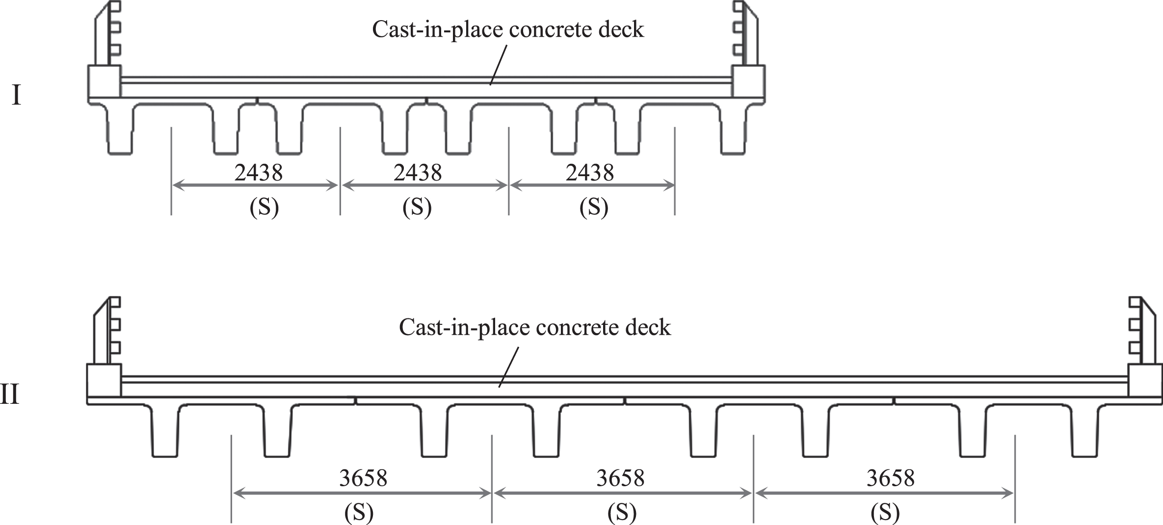
NEXT F beam bridge sections examined herein (Adapted from [6]; Unit: mm; S = beam spacing).
Bridge section, concrete strength, beam section, and span length for the NEXT F beam bridges examined herein
(Note: 1 ft = 304.8 mm; 1 ksi = 6.895 MPa).
Per AASHTO LRFD bridge design specifications [4]: the amount of prestressed and non-prestressed tensile reinforcement shall be adequate to develop a factored flexural resistance (M r ) at least equal to the lesser of “1.33M u ” and “1.2M cr ”, where M u = the factored moment required by the applicable strength load combination; M cr = cracking moment [4].
The following Equations (1–5) show the calculation of M
r
[4]:
M r = factored flexural resistance
φ= resistance factor
M n = nominal flexural resistance
A ps = area of prestressing steel
f ps = average stress in prestressing steel at nominal bending resistance
d p = distance from extreme compression fiber to the centroid of the prestressing tendons
a= depth of the equivalent stress block
A s = area of nonprestressed tension reinforcement
f s = stress in the nonprestressed tension reinforcement at nominal flexural resistance
d s = distance from extreme compression fiber to the centroid of nonprestressed tensile reinforcement
= area of compression reinforcement
= stress in the nonprestressed compression reinforcement at nominal flexural resistance
= distance from extreme compression fiber to the centroid of compression reinforcement
α1= stress block factor
= design concrete compressive strength
b= width of the compression face of the member
b w = web width
h f = compression flange depth
f pu = specified tensile strength of prestressing steel
k= 0.28 for low relaxation strand
c= distance from extreme compression fiber to the neutral axis
β1= stress block factor
Note that for a rectangular section behavior, “b
w
” shall be taken as “b ” in Equation (2) and Equation (5) [4]. The cracking moment M
cr
may be calculated with the following Equation (6) [4]:
f r = modulus of rupture of concrete
f cpe = compressive strength in concrete due to effective prestress forces only at extreme fiber of section where tensile stress is caused by externally applied loads
M dnc = total unfactored dead load moment acting on the monolithic or non-composite section
S c = section modulus for the extreme fiber of the composite section where tensile stress is caused by externally applied loads
S nc = section modulus for the extreme fiber of the monolithic or non-composite section where tensile stress is caused by externally applied loads
γ1= flexural cracking variability factor (1.2 for precast segmental structures; 1.6 for all other concrete structures)
γ2= prestress variability factor (1.1 for bonded tendons; 1.0 for unbonded tendons)
γ3= ratio of specified minimum yield strength to ultimate tensile strength of the nonprestressed reinforcement (γ3= 1.0 for prestressing steel)
In this study, it is assumed that the NEXT beams (non-segmental) are made with bonded prestressing strands. Thus, γ1= 1.6, γ2= 1.1, and γ3= 1.0 are used in this study. The current modulus of rupture of concrete (f r ) in AASHTO LRFD is (ksi), where = compressive strength of concrete used in design [4].
This study intended to evaluate the minimum flexural reinforcement requirements for NEXT beam bridges, therefore, a complete flexural design was performed for each bridge examined herein (see Table 2). Note that the design needs to be performed by satisfying the stress limits at transfer, service, and fatigue limit states and meeting the requirements for moment at the strength limit state and for the minimum flexural reinforcement [4, 10]. Two different span lengths were examined for each beam section (see Table 2), where the larger length is about the maximum beam length that the bridge can be designed by meeting all requirements as mentioned above. Based on the recent research from Ref. [11], the AASHTO LRFD live load distribution factors (LLDF) for moment for types i and k bridge cross-sections were used herein to calculate the live load moments in the exterior and interior beams in a bridge. Table 3 shows the AASHTO LRFD LLDF for moment for types i and k bridge cross-sections [4]. The design of prestressing strands in each NEXT beam was based on the typical reinforcement details in a NEXT F beam from Ref. [6], as shown in Fig. 4. Only prestressing strands were used in the beams (no longitudinal mild steel reinforcements); the prestressing strands in each stem are spaced at 2 in. on centers; all prestressing strands are straight (debond up to 25% of strands) and have a diameter of 0.6 in [6]. In addition, the following parameters are assumed with reference to [4, 10]: the thickness of the concrete deck is 8 in. (including half inch wearing surface) and the compressive strength of deck concrete is 4 ksi; three different compressive strength of beam concrete are assumed (see Table 2); the unit weight for future wearing surface is 25 psf; the barrier has a weight of 300 lb/ft and a base width of 18 in.; the prestressing strands used herein are seven-wire low-relaxation type and have a specified tensile strength f pu = 270 ksi [4, 10]. The LRFD approximate estimate of time dependent loss was used to compute the prestress loss [4]. Based on the assumptions mentioned above, the complete design of the 48 NEXT F beam bridges was performed with reference to [4, 10], after which M r , M cr , and M u at the mid-span section were compiled for comparison studies, as disccussed in the next section.
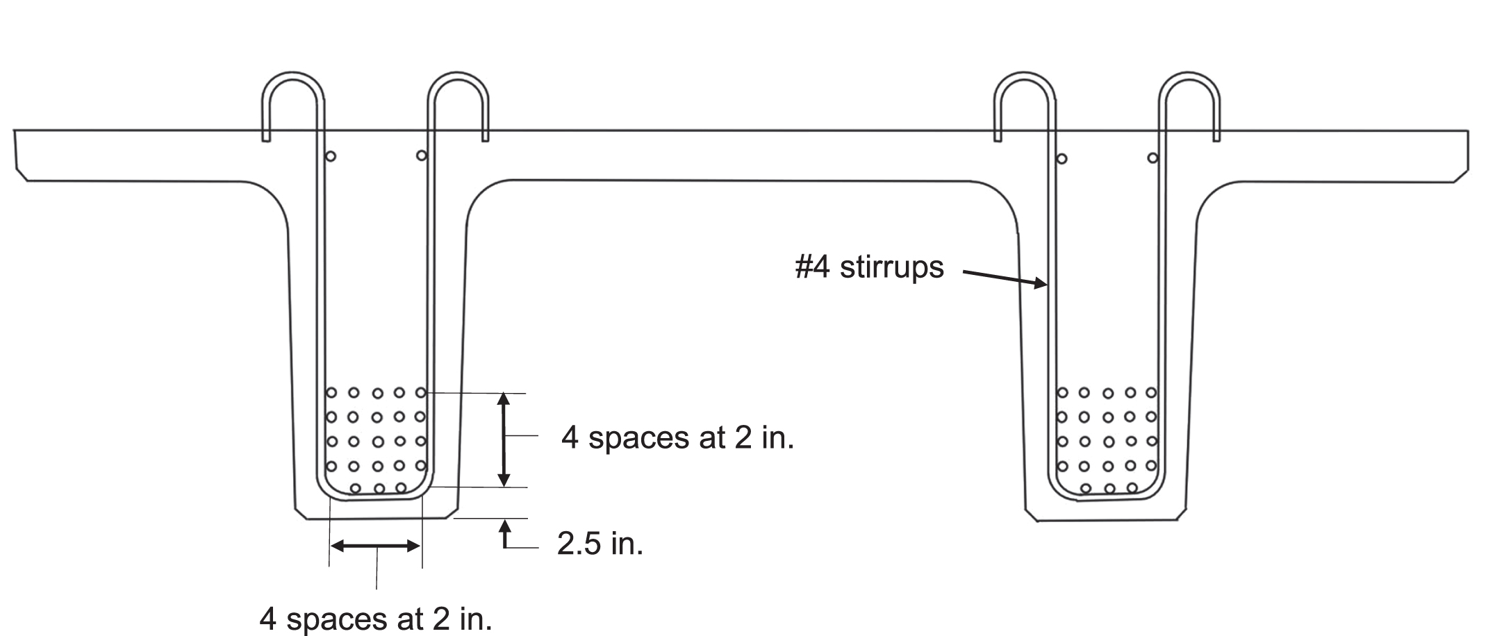
Typical reinforcement details in a NEXT F beam (Adapted from [6]; Note: 1 in = 25.4 mm).
AASHTO LRFD LLDF for moment for types i and k bridge cross-sections (Adapted from [4])
Note: Nb = number of beams; S = beam spacing (ft); L = span length (ft); ts = depth oconcrete slab (in) (Unit conversion: 1 ft = 304.8 mm; 1 in = 25.4 mm).
“1.33M u ” and “1.2M cr ” for exterior and interior beams
The requirement for the minimum flexural reinforcement in the AASHTO LRFD bridge design specifications is that Mr should be greater or equal to the lesser of “1.33 Mu” and “1.2Mcr” [4]. Thus, the values of “M
u
” and “M
cr
” were recorded for exterior and interior beams for each bridge designed herein. Thereafter, “1.33M
u
” and “1.2M
cr
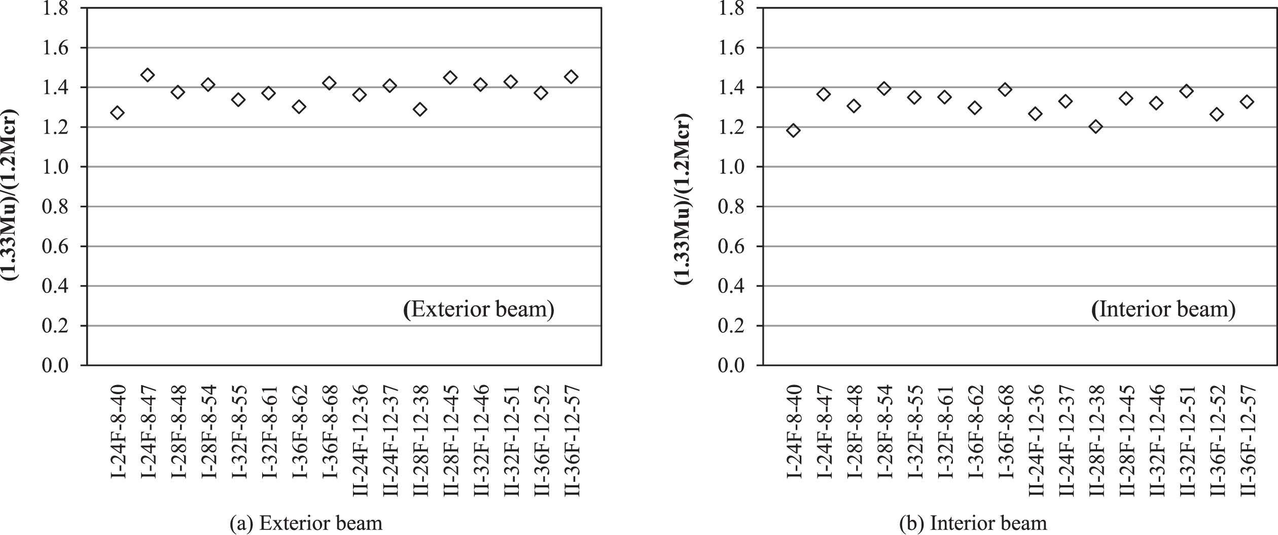
” were computed for comparisons. Figure 5 shows the ratio of (1.33Mu)/(1.2Mcr) for the bridges having a final concrete compressive strength of 6 ksi (i.e., = 6 ksi) with an initial concrete strength of 4 ksi (i.e.,
Ratio of “1.33Mu” to “1.2Mcr” ().
Ratio of “1.33Mu” to “1.2Mcr” ().
For bridges with = 6 ksi (see Fig. 5), the ratio of (1.33Mu)/(1.2Mcr) ranges from 1.27–1.46 and 1.18–1.39 for the exterior and interior beams, respectively. For bridges with = 8 ksi (see Fig. 6), the ratio of (1.33Mu)/(1.2Mcr) ranges from 1.34–1.51 and 1.30–1.44 for the exterior and interior beams, respectively.
For bridges with = 10 ksi (see Fig. 7), the ratio of (1.33Mu)/(1.2Mcr) ranges from 1.4–1.49 and 1.36–1.45 for the exterior and interior beams, respectively. As can be seen, all bridges examined herein have a ratio of (1.33Mu)/(1.2Mcr) greater than 1.0, for both exterior or interior beams, which means “1.2Mcr” controls the design for the minimum flexural reinforcement. Therefore, “Mcr” was used for checking the minimum reinforcement requirements, as discussed in the next section.

Ratio of “1.33Mu” to “1.2Mcr” ().
Figures 8–10 show the ratios of Mr/Mcr for the bridges with concrete strengths of 6 ksi, 8 ksi, and 10 ksi, respectively. In these figures, the Y-axis represents the ratio of Mr/Mcr, whereas the X-axis shows the bridges examined (the same as Figs. 5–7, each bridge is named by “bridge section –beam section –beam width –span length”).
Ratio of “Mr” to “Mcr” ().

Ratio of “Mr” to “Mcr” ().
Ratio of “Mr” to “Mcr” ().
For bridges with = 6 ksi (see Fig. 8): for exterior beams, the ratio of Mr/Mcr ranges from 1.33–1.5 and 1.24–1.39 for the bridges with section I and II, respectively; for interior beams, the ratio of Mr/Mcr ranges from 1.32–1.49 and 1.21–1.37 for the bridges with section I and II, respectively.
For bridges with = 8 ksi (see Fig. 9): for exterior beams, the ratio of Mr/Mcr ranges from 1.41–1.55 and 1.3–1.48 for the bridges with section I and II, respectively; for interior beams, the ratio of Mr/Mcr ranges from 1.41–1.55 and 1.24–1.46 for the bridges with section I and II, respectively.
For bridges with = 10 ksi (see Fig. 10): for exterior beams, the ratio of Mr/Mcr ranges from 1.43–1.57 and 1.41–1.55 for the bridges with section I and II, respectively; for interior beams, the ratio of Mr/Mcr ranges from 1.42–1.57 and 1.38–1.52 for the bridges with section I and II, respectively.
As can be seen, all beams in the bridges examined herein have a ratio of Mr/Mcr greater than 1.2, and the ratios of Mr/Mcr for the exterior and interior beams in each bridge are comparable. It is worth mentioning that the ratio of Mr/Mcr is an indicator of the level of safety against brittle failure after the first flexural cracks; a higher ratio of Mr/Mcr provides a higher level of safety against sudden failure after first flexural cracks [5]. Note that the beam may fail in shear, which is in a brittle manner [5]. Huang (2022) conducted a parametric study on the shear design of 48 NEXT beam bridges, which indicated that providing the minimum transverse shear reinforcement could offer a sufficient safety margin for shear for NEXT beam bridges [12]. Recent experimental research on post-tensioned girder specimens with reinforcement that is less that the AASHTO LRFD minimum required showed that the flexural cracking could propagate into inclined shear cracking toward mid-span and continued as a horizontal crack along the bottom of the top flange [5]. In this sense, providing transverse reinforcements in the beam could be potentially beneficial.
Overall speaking, bridges with section I (8 ft wide NEXT beams) have a ratio of 1.32–1.57; whereas bridges with section II (12 ft wide NEXT beams) have a ratio of 1.21–1.55; bridges with 8 ft wide beams tends to have higher ratio of Mr/Mcr than those bridges with 12 ft wide beams; in addition, the ratio of Mr/Mcr increases as the span length increases when the bridges have the same bridge section and beam section (e.g., “I-36F-8-81” vs. “I-36F-8-86”). It is also observed that the bridges with a concrete strength of 10 ksi appear to have a higher ratio of Mr/Mcr, and the ratios are more consistent among the bridges. For bridges with section II, several bridges have a ratio below 1.3 (i.e., 1.21 –1.29) for = 6 ksi; one bridge (i.e., “II-24F-12-40”) has a ratio below 1.3 for = 8 ksi; and no bridge has a ratio lower than 1.3 for = 10 ksi. For bridges with section I, all ratios of Mr/Mcr are greater than 1.30 for all concrete strengths. Based on the observations above, 12 ft wide NEXT beams may not be suitable for short-span bridges when < 8 ksi.
In this paper, the minimum flexural reinforcement requirements for NEXT F beam bridges were evaluated by a comprehensive parametric study, which included parameters of concrete strength, bridge section, beam section, and span length. A total of 48 NEXT F beam bridges were examined for both exterior and interior beams. Based on the results from this study, the following conclusions can be made: The ratios of Mr/Mcr for the exterior and interior beams are comparable for each bridge examined herein. The ratio of Mr/Mcr increases as the span length increases when the bridges have the same bridge section and beam section. Bridges with 8 ft wide beams tend to have a higher ratio of Mr/Mcr than those bridges with 12 ft wide beams. The ratios of Mr/Mcr for bridges with section I (8 ft wide beams) are greater than 1.30, regardless of the concrete strength. For bridges with section II (12 ft wide beams), several bridges have a Mr/Mcr ratio lower than 1.3 for = 6 ksi; one bridge has a ratio below 1.3 for = 8 ksi; and no bridge has a ratio lower than 1.3 for = 10 ksi. The bridges with a concrete strength of 10ksi tend to have a higher ratio of Mr/Mcr for bridges examined herein; and the ratios are more consistent among the bridges with = 10 ksi.
Even though all bridges examined herein have met the minimum reinforcement requirements (i.e., Mr/Mcr > 1.2), some bridges have a much lower ratio of Mr/Mcr than others. When < 8 ksi, 12 ft wide NEXT beams may not be suitable for short-span bridges. The research findings from this study could be useful for bridge engineers when designing a NEXT beam bridge.