Abstract
The inverse kinematics of robotic manipulators consists of finding a joint configuration to reach a desired end-effector pose. Since inverse kinematics is a complex non-linear problem with redundant solutions, sophisticated optimization techniques are often required to solve this problem; a possible solution can be found in metaheuristic algorithms. In this work, a modified version of the firefly algorithm for multimodal optimization is proposed to solve the inverse kinematics. This modified version can provide multiple joint configurations leading to the same end-effector pose, improving the classic firefly algorithm performance. Moreover, the proposed approach avoids singularities because it does not require any Jacobian matrix inversion, which is the main problem of conventional approaches. The proposed approach can be implemented in robotic manipulators composed of revolute or prismatic joints of
Introduction
Many robotics applications such as visual guided tasks, object grasping, trajectory tracking, and control problems require the solution of the inverse kinematics of robot manipulators. Robot manipulators can have redundant joint configurations leading to the same end-effector pose [1]. Moreover, the inverse kinematics is a nonlinear problem, and due to its redundancy solution, this problem is a difficult task to solve [2]. Multiple joint configurations can be used to overcome issues such as robotic manipulators working in environments with the presence of obstacles, joint solutions of impossible execution due to physical restrictions, or joint configurations with abrupt changes during a trajectory planning task. For these reasons, it is crucial to find a set of joint configurations that reach the same end-effector pose to choose a suitable solution for the inverse kinematics task.
Conventional closed-form approaches such as the geometric and algebraic methods can be used to solve the inverse kinematics [3]. These approaches provide exact solutions. Moreover, some kinematics equations can provide multiple joint solutions for the same end-effector pose. However, as the total number of degrees of freedom (DOF) of the manipulator increase, the closed-form method becomes difficult to implement. Consequently, closed-form approaches are difficult to generalize. Other conventional approaches based on differential kinematics use a Jacobian matrix to solve the inverse kinematics [4]. These methods are commonly used because they provide remarkable approximations, and they can be generalized to different manipulator structures. The main inconvenience with these approaches is the singularities. These methods require the inversion of the Jacobian matrix, which depends on the actual joint configuration. However, some joint configurations provoke the Jacobian matrix to become rank deficient. This inconvenience produces a high demand for joint velocities of inadmissible execution. Additionally, these approaches only provide a single solution for the inverse kinematics. Due to the complexity and nonlinearities [5], metaheuristics algorithms should be considered to solve this problem [6].
Metaheuristics algorithms have been widely used to solve optimization problems in different researches areas [7]. In the field of robotics, researches implement these approaches to solve other robotic applications such as mobile robot control [8, 9], mobile robot navigation [10, 11], control of parallel robot platform [12], online optimization of manipulator trajectories [13], online tuning of a PID for mobile robots [14], training of a neural network to obtain the kinematic modeling of robot manipulators [15], and others [16]. These metaheuristics are often required to deal with problems that are generally difficult to solve.
The use of metaheuristics algorithms overcomes the inconvenience of singularities. Several authors have commonly implemented particle swarm optimization (PSO) to solve the inverse kinematics for different manipulator structures [2, 17, 18, 19]. The Genetic Algorithms (GA) and their modifications have also been implemented [20, 21, 22, 23]. Moreover, comparative studies have been realized to compare the performance of different metaheuristics such as Differential Evolution (DE), Gravitational Search Algorithm (GSA), Artificial Bee Colony (ABC), Firefly Algorithm (FA), Cuckoo Search (CS), and others [24, 25, 26]. The FA algorithm has been applied to solve the inverse kinematics for redundant manipulators [27, 28]. Other metaheuristic approaches have proved to be superior to other compared metaheuristics [29, 30, 31, 32, 33, 34, 35, 36, 37, 38, 39]. However, these approaches are used for global optimization.
In multimodal optimization, we can simultaneously find many global and local optima for a given optimization problem [40]. There are several metaheuristics algorithms to search for multiple optima. Adaptations of DE and GA have been implemented based on the crowding methods [41, 42]. A modification to DE has been developed for multimodal optimization based on the fitness sharing scheme [41, 43]. There exists a version of PSO adapted to multimodal optimization based on speciation strategy [44]. Another strategy has been implemented in Flower Pollination Algorithm (FPA) and CS to provide multimodality. This strategy consists of three fundamental parts: a memory mechanism, an acceleration process for detecting potential local minima, and a depuration procedure to eliminate similar solutions. The modified algorithm is called MFPA [45] and MCS [46]. They have been compared against crowding, fitness sharing and speciation methods, where they proved to be superior regarding more consistent optima solutions. Other approaches based on niching methods such as real-coded GA [47, 5] have been implemented to solve inverse kinematics tasks. However, these approaches solved the required position of the end-effector without considering its orientation. The applicability of these methods is limited to manipulator structures with revolute joints and simulations without considering real joint limits.
Previously, we used metaheuristics algorithms to solve the inverse kinematics for robot manipulators [48], mobile manipulators [49], and dual-arm robotic systems [50]. These approaches provide single joint solutions since they solve the inverse kinematics as a global optimization problem. In this work, we propose to use a modified version of FA to provide multiples solutions simultaneously. The proposed modified version improves the FA multimodal capability without losing the balance between exploration and exploitation, where good communication among fireflies is maintained. The FA algorithm has been designed with multimodal capacities [51], an advantage over the revised multimodal algorithms. FA has an update mechanism that already deals with multimodality, while the revised methods were adapted to deal with multimodal optimization. Moreover, FA has been used to solve the inverse kinematics [26, 52]. However, these approaches provide only an optimal global solution. Similarly, there exist several modifications to FA [53, 54, 55], but these methods focus on improving its single global solution instead of improving its multimodality capability.
The contributions of this paper are given below. The proposed approach solves the inverse kinematics as a multimodal constrained optimization problem. Thanks to the modified FA version, the proposed method can provide multiple joints configurations under joint limits constrains, which reach the same end-effector pose. Moreover, the proposal is based on the Denavit-Hartenberg (DH) convention because the forward kinematics always have a solution. The proposed method does not require any inversion of a Jacobian matrix; for this reason, it does not suffer from singular configurations. Additionally, this method can be implemented under robotic manipulators with
This paper is organized as follows: The next Section will introduce the basic concepts about the forward and inverse kinematics for robotic manipulators. In Section 3, the description of FA and its modification are given. Then, we give a detailed description of the proposed approach in Section 4. In Section 5, simulations, comparisons, non-parametric statistical tests, and real experiments are presented. Finally, we give conclusions in Section 6.
Robotic manipulator kinematics
Robotic manipulators are composed of a series of links connected by joints, which form an open kinematic chain [1]. The last element in the kinematic chain is called end-effector. Each joint is associated with an articulation, and they define a joint configuration
Kinematic chain of a serial robotic manipulator. 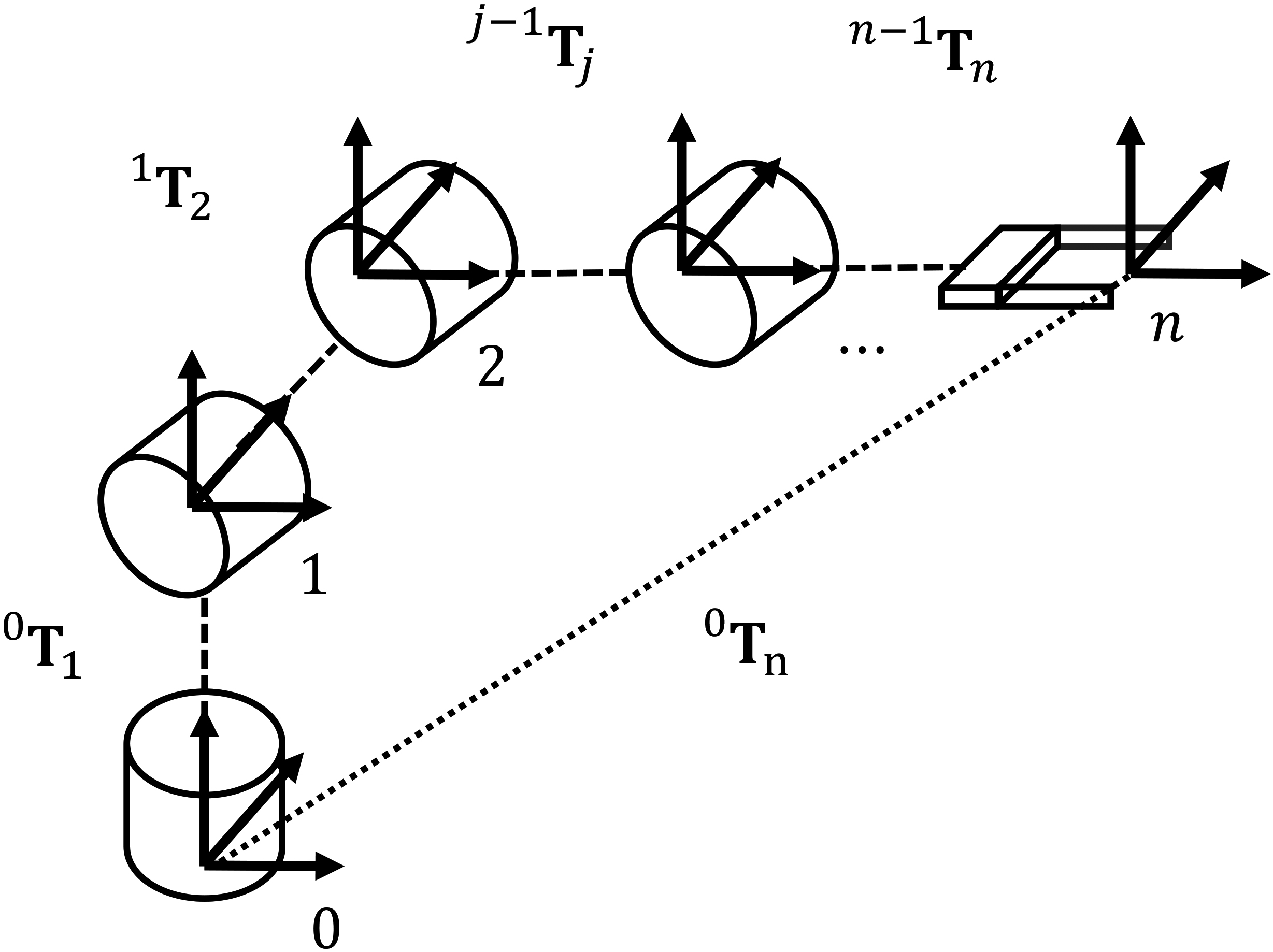
There are two types of articulations, the revolute and prismatic joints. A joint variable
where
Forward kinematics consists of computing the end-effector pose given a joint configuration. Forward kinematics is a straight forward problem that always has a solution. Forward kinematics can be expressed as follows
where each link
Based on the Denavit-Hartenberg (DH) model, we can express the homogeneous matrix
where the
The homogeneous matrix
where
Inverse kinematics consists of computing the required joint configuration to reach the given end-effector pose. Inverse kinematics is not a straight forward problem, and it may have multiple solutions. The geometric and algebraic approaches produce the exact solution for the inverse kinematics problem, and they can provide multiple joint solutions. However, these methods become complicated to implement in complex kinematics structures with high DOF, and there is not always a closed-form solution. Numerical methods produce significant approximations for the inverse kinematics. The main disadvantage in these approaches is the singularities. They require the inversion of a Jacobian matrix that can become rank deficient. Additionally, these methods provide a single joint solution.
The inverse kinematics can be solved by minimizing an error between the desired and the actual end-effector positions. Multiple joint configurations may lead to the same end-effector position since the inverse kinematics is a nonlinear problem. Figure 2 illustrates the multimodal function given by an error function of a 2 DOF planar manipulator. This manipulator is composed of two links with
The multimodal function of the inverse kinematics problem of a 2 DOF planar manipulator.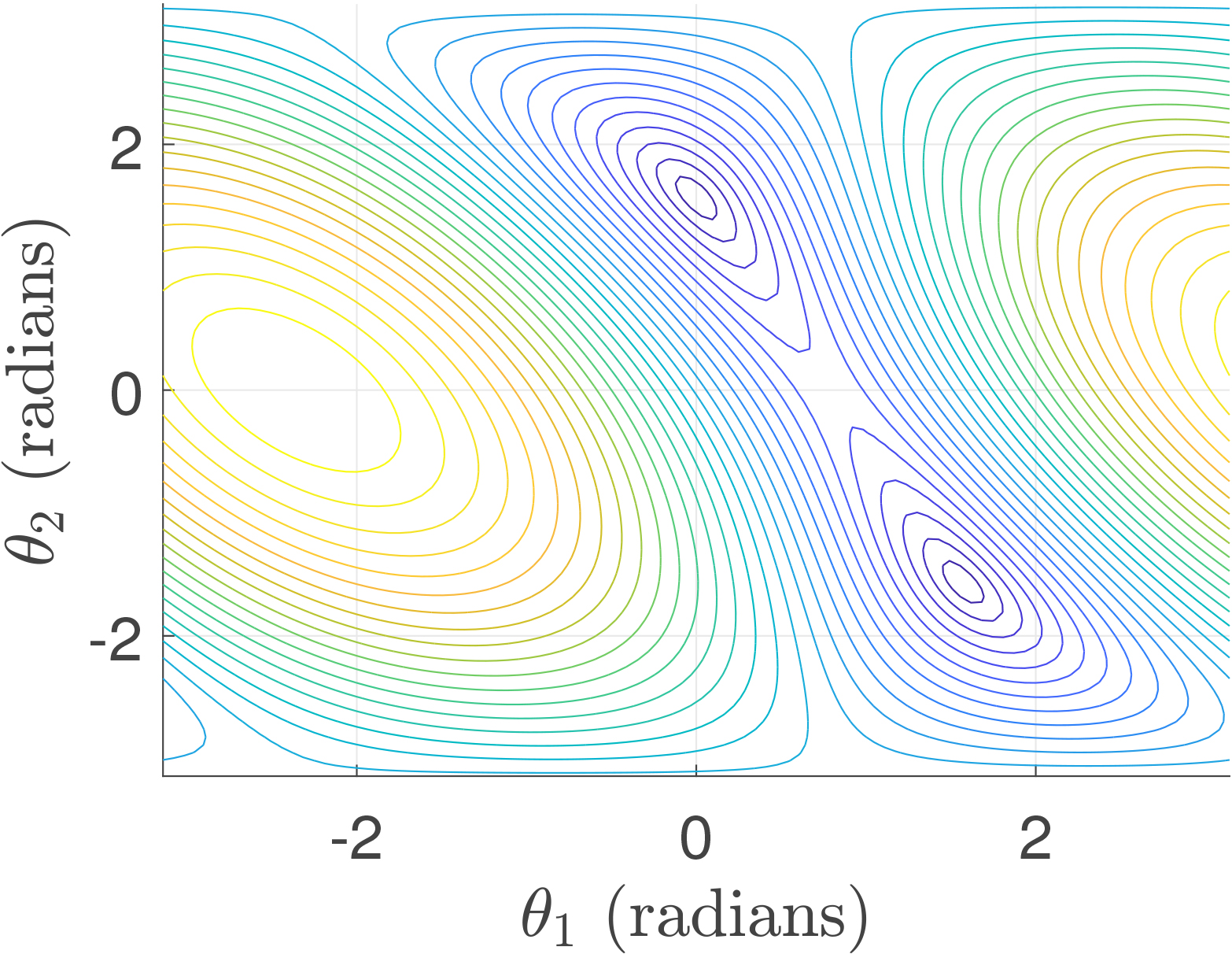
In this work, a modified version of FA is proposed to deal with multiples joint configuration. Moreover, the proposed approach solves the inconveniences of conventional methods.
A detailed description of the forward and inverse kinematics can be found in [1, 3, 4].
The Firefly Algorithm (FA) is a metaheuristic method inspired by the attraction behavior among fireflies [51]. FA is conformed by a population of fireflies, where every firefly is associated with a brightness intensity. The landscape of an objective function produces this bright intensity. If a firefly is located near a local or global optimum, its bright intensity becomes higher. Those fireflies with high brightness intensity are more attractive. In other words, a firefly is attracted to another that is brighter than itself. Moreover, the attraction behavior exponentially decreases by the distance among fireflies.
In FA, a firefly
where
When
The distance among two fireflies
Another important characteristic in FA is the reduction of the parameter
where
For further information about FA, please go to references [51, 56].
Classical FA has a good balance between exploration and exploitation controlled by the parameters
There are different strategies to provide a good performance about feedback behavior in metaheuristic. In PSO, every particle knows its current position but also knows its best position acquired so far. PSO uses this information to avoid losing the quality of the position in the swarm population. Other evolutionary computing algorithms, such as DE and Evolution Strategies (ES) [57], performed a selection operation to provide feedback characteristics. This selection operation consists of comparing offspring solutions against parent solutions. Offspring replace parent solutions only if they yield better solutions. Teaching-Learning Based Optimization (TLBO) [57] and ABC also performed a similar operation. These algorithms produce new candidate solutions, but they are abandoned if they perform poorly. This selection operation is simple, and it provides excellent results.
In this work, we proposed a simple modification to the classical FA to provide a better feedback characteristic inspired by the selection operation. By modifying the feedback behavior, FA will improve its multimodal capability without losing its performance in exploration, exploitation, and communication behaviors.
The modification to the classical FA is simple, and it is conducted as follows. We proposed to update the position of a firefly
where
where firefly
In Eq. (8), a firefly
The definition of an end-effector pose is needed to solve the inverse kinematics. The end-effector pose is represented as
where
An objective function is defined as an error between the desired
where
where it is considered the error between the desired
Robotic manipulators with at least 6 DOF can reach any desired end-effector pose inside of its workspace. For this case, the objective function Eq. (12) is highly recommended because the manipulator can solve the required end-effector position and orientation. However, several robotic manipulators have less than 6 DOF, where it is not possible to reach some specific end-effector poses. For this reason, most of these manipulators only solve the desired position. In this case, the objective function Eq. (13) is adequate to solve the inverse kinematics.
In this work, we proposed to solve the inverse kinematics as a constrained optimization problem defined as
where
FA was designed to work in continuous spaces without considering constraints. To include the constrains in mFA optimization process, we propose to follow the next scheme
where
where
The proposed algorithm to solve the inverse kinematics of robot manipulator based on mFA is shown in Algorithm 4.
[htb] [1] initialize
Simulation and real experiments were carried out to test the performance of the proposed approach for solving the inverse kinematics of robotic manipulators. We are interested in testing the capability for finding multiple joint solutions for the same desired end-effector pose. These joint solutions must provide accurate results concerning the desired end-effector pose. We also consider testing the robustness to solve the inverse kinematics of different robotic manipulator structures.
Simulation results
Simulations aim to test the performance of the proposed mFA against the classical FA for solving the inverse kinematics problems. We also consider comparing the mFA against MFPA and MCS multimodal algorithms. There is a constrained version of FA [58], where a random vector is computed considering each position of fireflies and the value of the search space boundaries. This random vector indicates how the firefly needs to move to handle the given constraints. Since the proposed approach also handles constraints, the constrained FA is also considered for comparisons. We called this method CFA.
The common parameter settings of the considered algorithms are the total numbers of iterations and population members. We defined a total of
Simulations are conducted as follows: In the first part, the inverse kinematics tasks require solving the end-effector desired position. On the other hand, the second part requires both the desired position and orientation of the end-effector for the given inverse kinematics tasks.
To present the obtained results of simulations to show accuracy, we proposed to measure the following errors
where
To estimate the number of joint solutions found by the multimodal algorithms, we proposed to use two well-known algorithms for clustering, which are Subtractive Clustering (SC) [59] and Density-Based Spatial Clustering of Applications with Noise (DBSCAN) [60]. The input data are the final population members, and the center of each cluster represents the final joint solution. These clustering algorithms are necessary because no priority knowledge about the total number of joint solutions is provided. In the case of SC, we set a range of influence to 0.9. For DBSCAN, we set a search radius to 0.9 as well. It is important to mention that the joint solutions with position errors above 10 millimeters are not considered for clustering.
DH table for a Planar manipulator of 2 DOF
DH table for a Planar manipulator of 3 DOF
DH table for an Anthropomorphic manipulator of 3 DOF
The robotic manipulators considered for these simulations are two Planar manipulators of 2 DOF and 3 DOF, an Anthropomorphic manipulator of 3 DOF, a Scara manipulator of 4 DOF, and a Puma 560 manipulator of 6 DOF. The DH tables of these manipulators are presented in Tables 1–5, respectively. These robots are often used as educational examples in robot kinematics [1, 3].
DH table for Scara manipulator of 4 DOF
DH table for Puma 560 manipulator of 6 DOF
Another important aspect to mention is the restrictions. For these simulations, the joint limits were selected as
where
The simulations were implemented in Matlab™. Every multimodal algorithm ran 25 times, and their results were illustrated using box plots. We used box plots to display graphically statistical variation for the considered algorithm results. In the simulations, the number of solutions found, the position and orientation errors are presented into box plots. We are interested in finding the algorithm with the smaller data distribution, the lower value results, and fewer outliers.
For the first part of the simulations, we considered the following robotic manipulators and their respective desired position of the end-effector
Planar manipulator of 2 DOF with the desired position Anthropomorphic manipulator of 3 DOF with the desired position Puma 560 manipulator of 6 DOF with the desired position
The simulation results for the Planar manipulator of 2 DOF are presented in Fig. 3. For both SC and DBSCAN algorithms, the MFPA, MCS, and mFA methods reported two joint configurations leading the same end-effector pose, while FA and CFA reported only one solution. With respect to the position error provided by SC algorithm in Fig. 3(c), the results reported a high value for MCS and CFA compared against MFPA, FA and mFA; however, MFPA presented outliers. Indeed, FA and mFA provided error values under 0.5 millimeters. The results of CFA, MFPA, and MCS also reported a large data distribution. In Fig. 3(d), CFA showed larger data distribution in the position error provided by DBSCAN. However, the other algorithms reported results below 0.1 millimeters of error.
Inverse kinematics results for the Planar manipulator of 2 DOF, where only a desired position of the end-effector was required. The number of solutions clustered by SC is presented in (a) and by DBSCAN in (b). The position error for the center of the clusters provided by SC and DBSCAN is presented in (c) and (d), respectively. 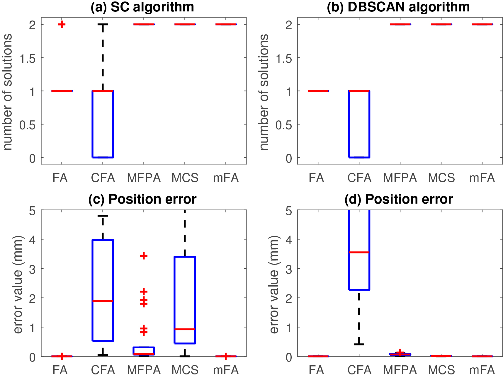
In Fig. 4, the simulation results for the Anthropomorphic manipulator of 3 DOF are reported. MFPA, MCS, and mFA founded four joint solutions. In contrast, FA algorithms reported large data distribution with a median value of two solutions, see Fig. 4(a). CFA also reported a large data distribution. On the other hand, four joint solutions are also reported by DBSCAN for MFPA, MCS and mFA approaches. Only one solution is reported by FA, see Fig. 4(b). In Fig. 4(c), MCS reported the larger data distribution with 4 millimeters of error. FA and mFA showed similar results with an error below to 0.01 millimeters. Similar results for FA and mFA are presented in Fig. 4(d). In this case, these two approaches performed better than the others. MFPA and MCS illustrated a large data distribution, but the error results of both approaches are presented under an error of 0.8 millimeters. The performance of CFA for position error is poorly compared against the others.
Inverse kinematics results for the Anthropomorphic manipulator of 3 DOF, where only a desired position of the end-effector was required. The number of solutions clustered by SC is presented in (a) and by DBSCAN in (b). The position error for the center of the clusters provided by SC and DBSCAN is presented in (c) and (d), respectively.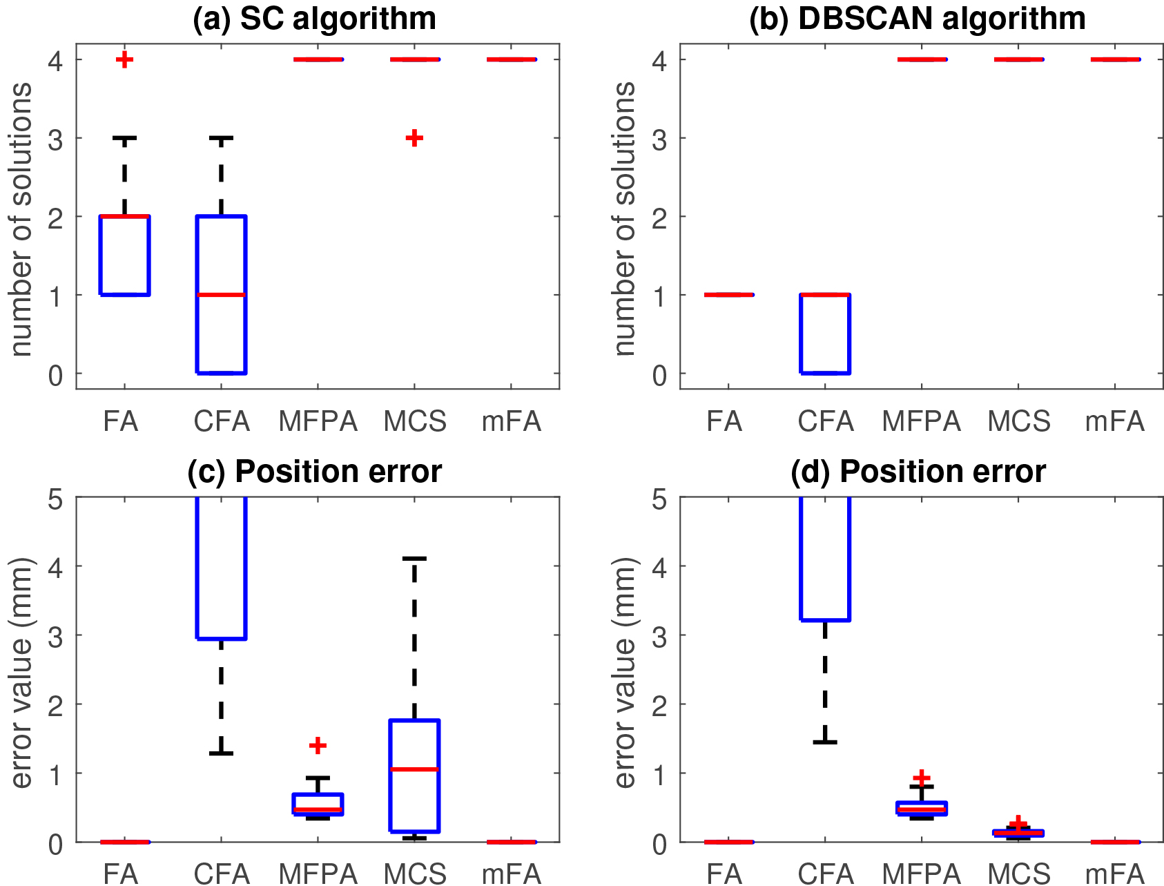
Figure 5 shows the simulation results for the Puma 560 manipulator of 6 DOF. MFPA and CFA did not report joint solutions in this test. The boxplots for both clustering algorithms showed outlier data for MFPA. Moreover, MFPA found a solution that is not considered as a result. Similarly, there are cases when CFA did not report solutions. For these reasons, Fig. 5(c) and (d) did not show any results for MFPA and CFA. MCS reported in Fig. 5(a) a large data distribution in the number of joint solutions found by SC. In this case, the minimum number of the solution was two, and the maximum was seven. However, Fig. 5(b) shows a small data distribution with a median value of 4 solutions. The number of clusters reported by SC might be more than expected. In Fig. 5(c) and Fig. 5(d), the FA and the mFA performed better than MCS with error values below to 1 millimeter. However, FA reported one solution clustered by DBSCAN and a median value of two solutions by SC. As we can see, MFPA performed poorly in this test. In contrast, the proposed mFA outperformed the other compared approaches.
Inverse kinematics results for the Puma 560 manipulator of 6 DOF, where only a desired position of the end-effector was required. The number of solutions clustered by SC is presented in (a) and by DBSCAN in (b). The position error for the center of the clusters provided by SC and DBSCAN is presented in (c) and (d), respectively.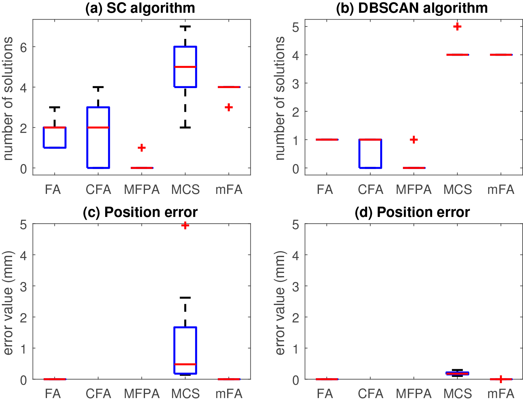
For the second part of simulations, we considered the following robotic manipulators and their respective desired position and orientation of the end-effector
Planar manipulator of 3 DOF with the desired pose
Scara manipulator of 4 DOF with the desired pose
Puma 560 manipulator of 6 DOF with the desired pose
The simulation results for the Planar manipulator of 3 DOF are given in Fig. 6. FA reported a larger data distribution for the joint solution clustered by SC, with a minimum value of one solution and a maximum of three solutions, see Fig. 6(a). However, DBSCAN reported only one joint solution, see Fig. 6(b). Moreover, MFPA, MCS, and mFA reported similar results where SC and DBSCAN provided two joint solutions. CFA presents the largest data distribution. The position and orientation errors for both SC and DBSCAN clusters are very similar, see Fig. 6(c)–(f). In all cases, FA and mFA outperformed the other approaches with position error values below 0.1 millimeters of error. CFA reported the larger data distribution in both the position and orientation errors. MFPA also presented a large data distribution.
Inverse kinematics results for the Planar manipulator of 3 DOF, where a desired position and orientation of the end-effector were required. The number of solutions clustered by SC is presented in (a) and by DBSCAN in (b). The position error for the center of the clusters provided by SC and DBSCAN is presented in (c) and (d), respectively. Orientation errors are also presented in (e) and (f), respectively.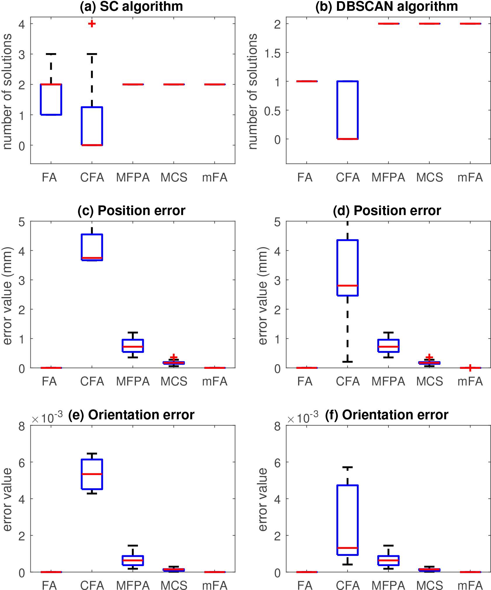
Figure 7 reports the simulation results for the Scara manipulator of 4 DOF. The behavior of the compared approaches is similar to the previous test. In Fig. 7(a) and 7(b), two joint solutions are reported for both SC and DBSCAN. Nevertheless, SC reported many joint solutions for FA, while DBSCAN reports one solution. SC poorly predicts the number of clusters for FA. We notice that CFA did not solve the inverse kinematics for this test. For this reason, the position and orientation results are not reported by CFA. The position error results are shown in Figs 7(c) and 7(d), where FA and mFA performed better than the other approaches with values below 0.1 millimeters. In contrast, MFPA and MSC presented bigger error results. All the algorithms reported small orientation errors, see in Fig. 7(e) and 7(f). However, FA and mFA showed the smallest data distribution. For both the position and orientation error, the MFPA presented the larger data distribution.
Inverse kinematics results for the Scara manipulator of 4 DOF, where a desired position and orientation of the end-effector were required. The number of solutions clustered by SC is presented in (a) and by DBSCAN in (b). The position error for the center of the clusters provided by SC and DBSCAN is presented in (c) and (d), respectively. Orientation errors are also presented in e) and (f), respectively.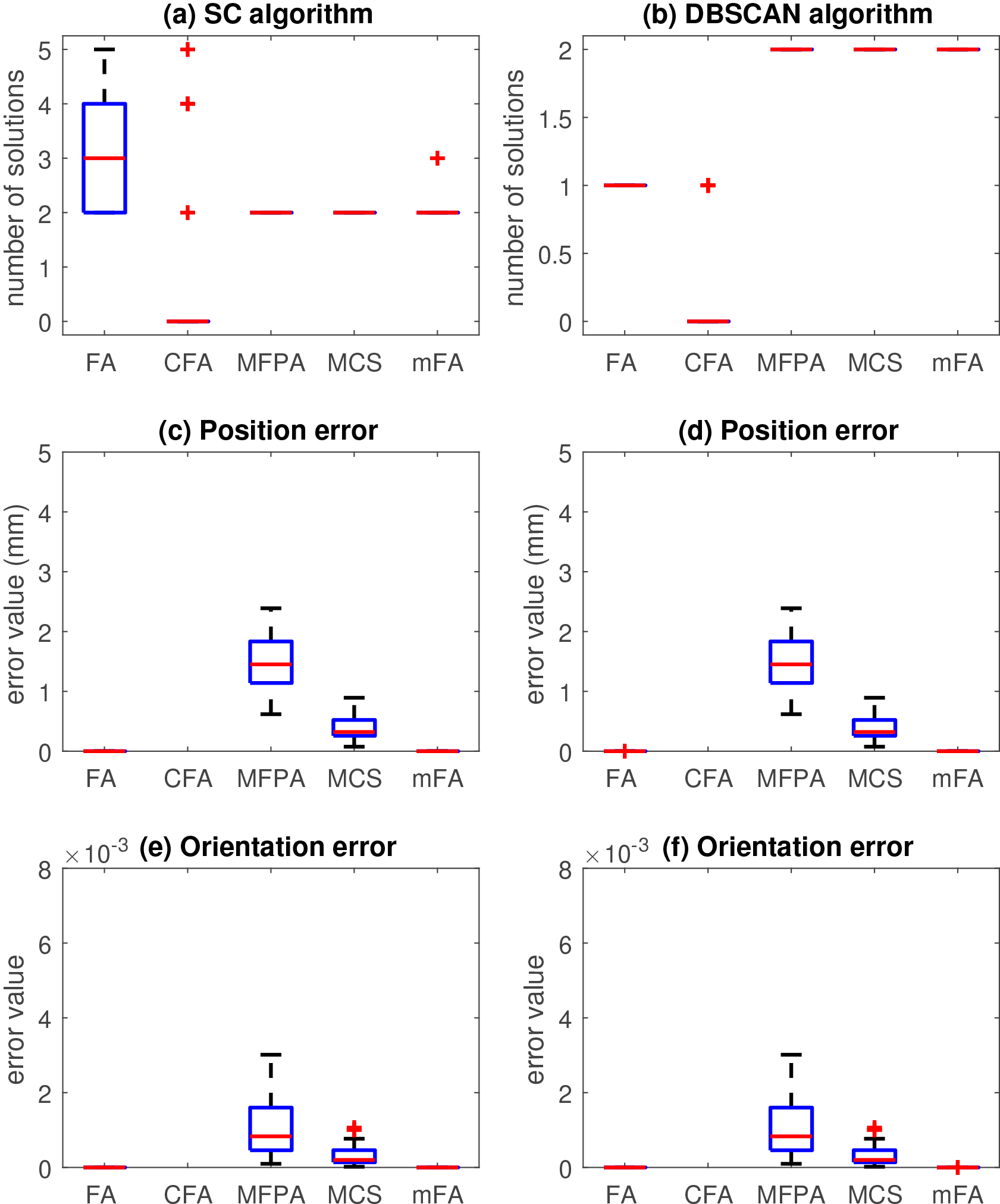
Finally, the simulation results for the Puma 560 manipulator of 6 DOF are presented in Fig. 8. FA reported the larger data distribution in the number of joint solutions clustered by CS, see Fig. 8(a). On the other hand, DBSCAN found just one solution, see Fig. 8(b). mFA outperformed the compared approaches by finding a median value of eight joint solutions reported by SC and DBSCAN. The MCS reported a maximum number of four solutions for both clustering algorithms with a large data distribution. Boxplots reported that there are some cases where MCS did not present any solution. Moreover, MFPA and CFA performed poorly. The results for both SC and DBSCAN reported that a few joint solutions were found, but they are considering noise data. In Fig. 8(c) and 8(d), FA and mFA reported error results with values below to 1 millimeter. However, FA reported the smallest data distribution. MCS had the largest data distribution, with error values of up to 7 millimeters. In the case of the orientation error in Fig. 8(e) and 8(f), the results reported small errors, which indicate that orientation problems were solved successfully for all compared approaches.
Inverse kinematics results for the Puma 560 manipulator of 6 DOF, where a desired position and orientation of the end-effector were required. The number of solutions clustered by SC is presented in (a) and by DBSCAN in (b). The position error for the center of the clusters provided by SC and DBSCAN is presented in (c) and (d), respectively. Orientation errors are also presented in (e) and (f), respectively.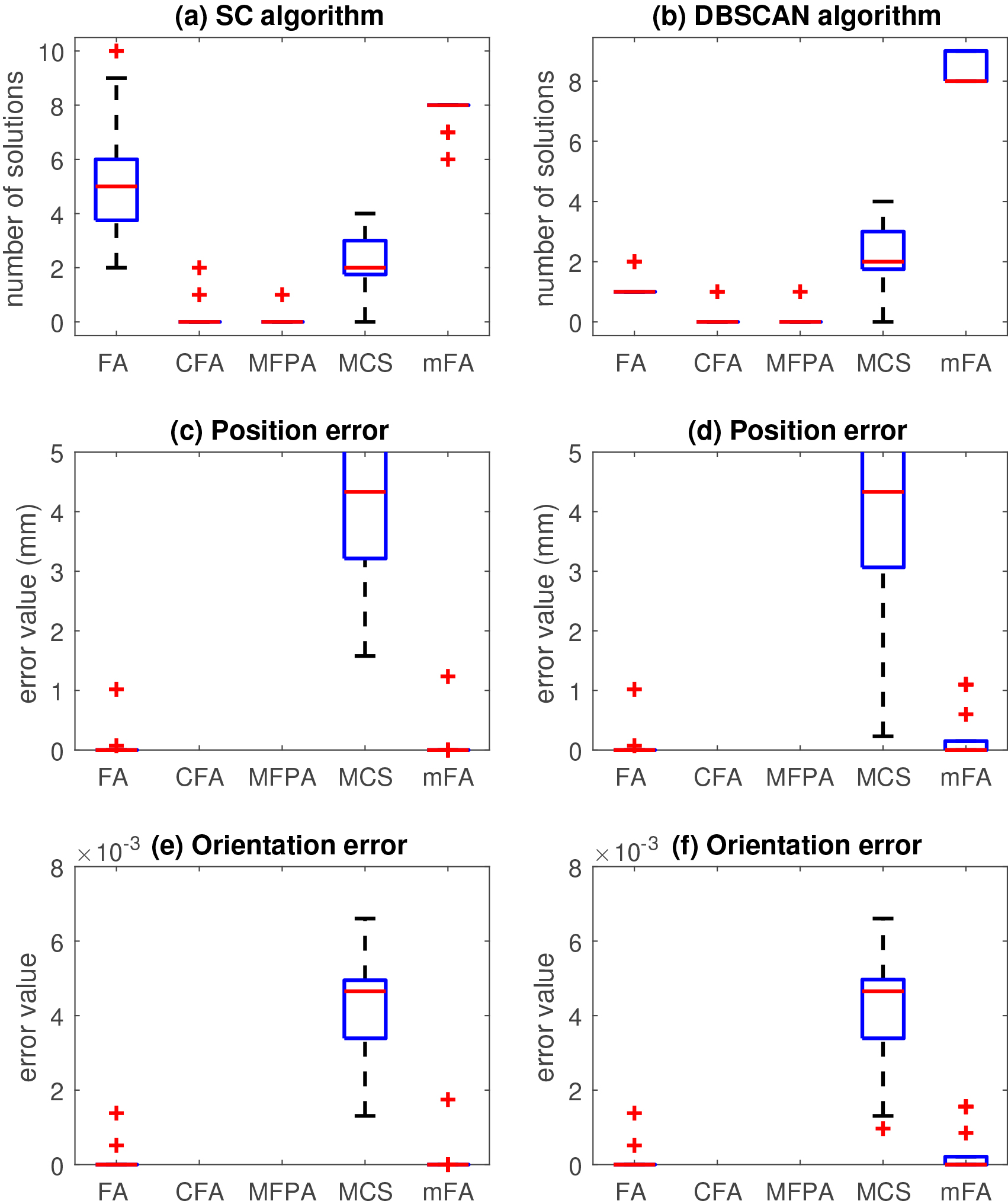
Based on simulations, FA and mFA performed similar respect to position and orientation error results. In contrast, mFA proved to be superior to FA for finding more joint solutions for the given problems. These results demonstrate that the proposed mFA highly improves the multimodal capability of classical FA without losing its exploration and exploitation capacities. Moreover, the statistical variations of mFA are better than the compared approaches. MFPA and CFA were not able to solve the given problems for the Puma 560 manipulator. The MCS also performed poorly for this manipulator.
Comparison results between the proposed mFA algorithm and the geometric approach.
On the other hand, MFPA and MCS provided good results concerning position error, orientation error, and the number of joint solutions reported for the manipulators with 2 DOF and 3 DOF. These results indicate that the inverse kinematics for manipulators with 4 DOF and 6 DOF is more challenging to solve. We notice that CFA performed poorly in all tests, respecting the number of solutions founded and the position error results. For the clustering methods used to report the total number of joint solutions, SC performed poorly compared with DBCAN. DBSCAN reports more consistent, clustering results.
The computational complexity of FA algorithm is
The geometric approach provides exact solutions for the inverse kinematics. This method also provides multiples solutions. However, complicated analysis of kinematics structures is required for high DOF. In this work, the proposed mFA is compared to the geometric approach. This comparison demonstrates the accuracy of the proposal compared to the exact solutions.
The robot manipulator Puma 560 is considered in this test. Give a desired position of the end-effector, the geometric approach may compute up to four joint configurations for this manipulator. In [47], the author reported five desired positions where four joint solutions can be found. The desired positions are listed below
Since only the desired position is required, the first 3 DOF of Puma 560 are needed to solve the inverse kinematics. The parameter settings for mFA are the same from simulations. This test was perform using Matlab™, where the mFA only ran once for each desired position. More details about the geometric approach for Puma 560 can be found in [47].
The results of the comparison are presented in Table 6. Every test corresponds to a desired position of the end-effector. As can be seen, the Euclidean norm results indicate that mFA provides joint configuration results with high accuracy compared with the exact solution computed by the geometric approach. Moreover, the position error results
Non-parametric statistical tests are usually employed to decide when an algorithm shows a significant difference compared to other algorithms [62]. In the non-parametric procedure, the null hypothesis and the alternative hypothesis are defined. The null hypothesis indicates that the algorithms are statistically equivalent, while the alternative hypothesis indicates that they are statistically different. Moreover, a p-value is computed to provide information about the significance of the statistical hypothesis. Smaller
Pairwise comparison of mFA against FA and MCS algorithms under the Sign test. The position error results of Planar of 2 DOF, Anthropo-morphic of 3 DOF, and Puma 560 of 6 DOF manipulators were used in this test
Pairwise comparison of mFA against FA and MCS algorithms under the Sign test. The position error results of Planar of 2 DOF, Anthropo-morphic of 3 DOF, and Puma 560 of 6 DOF manipulators were used in this test