





Abstract
The standard method for measuring magnetic properties of permanent magnets is the closed circuit method using an iron-cored electromagnet. With the advances of modern high quality permanent magnetic materials, it has become more and more important to measure their magnetic properties accurately both at room and elevated temperatures. Many problems have arisen when using this traditional DC hysteresigraph to test these new materials, such as those based on rare earth intermetallic compounds, bonded magnetic materials and nanocrystalline exchange-coupled magnets. The physical knowledge on these principal problems including magnetic properties of material, magnetic properties of product, specimen, uniform magnetization, saturation magnetization, the influence of the saturation of the poles, and the influence of Hall probe, etc., is important in the research and development of new materials and also nondestructive evaluation (NDE). These problems are discussed in this paper qualitatively and the current statuses to solve these problems are also presented.
Introduction
The permanent magnetic materials (PMMs) have found ever-increasing uses in both industry and home, and now are indispensable components of many modern devices. In our everyday life, their uses are surprisingly numerous and often go unnoticed. Many new applications are still continually emerging in industrial applications. Wind turbines and other magnet generator and motor based technologies have held their position and rely strongly on the performance of PMMs. Energy saving and efficiency would be a big concern for automobile and electric appliances, high performance permanent magnets (PMs) such as BaM, and rare-earth transition-metal (RE-TM) magnets will play an increasingly important role in these applications. Furthermore, PMMs are also frequently used in other areas of science and technology, such as military security, magnetic labeling, paleomagnetism, magnetoarchaeology, biomedical applications in the areas of diagnosis (e.g. bio-magnetic measurement in human body using magnetic biosensor detection systems), therapy (such as magnetic hyperthermia), actuating, imaging and drug delivery, mines detection, displacement or proximity testing, current measurement, magnetic sensor in navigation, and nondestructive evaluation (NDE) of materials, the applications listed above are just a few [1]. At every step in the study, preparation, production, business and application of PMMs, measurements are needed [2]. On the other hand, during their development, improvement and use, agreements must be made on the methods and procedures of measurement to ensure the reproducibility of results. The practical applications of magnetic measurements are almost unlimited [1].
The magnetic characterization of magnetic materials has two basic goals: (1) the measurement of the intrinsic magnetic (structure in-sensitive) parameters, such as saturation magnetization Ms, magnetic anisotropy
Demagnetization curve and related parameters of a permanent magnetic material.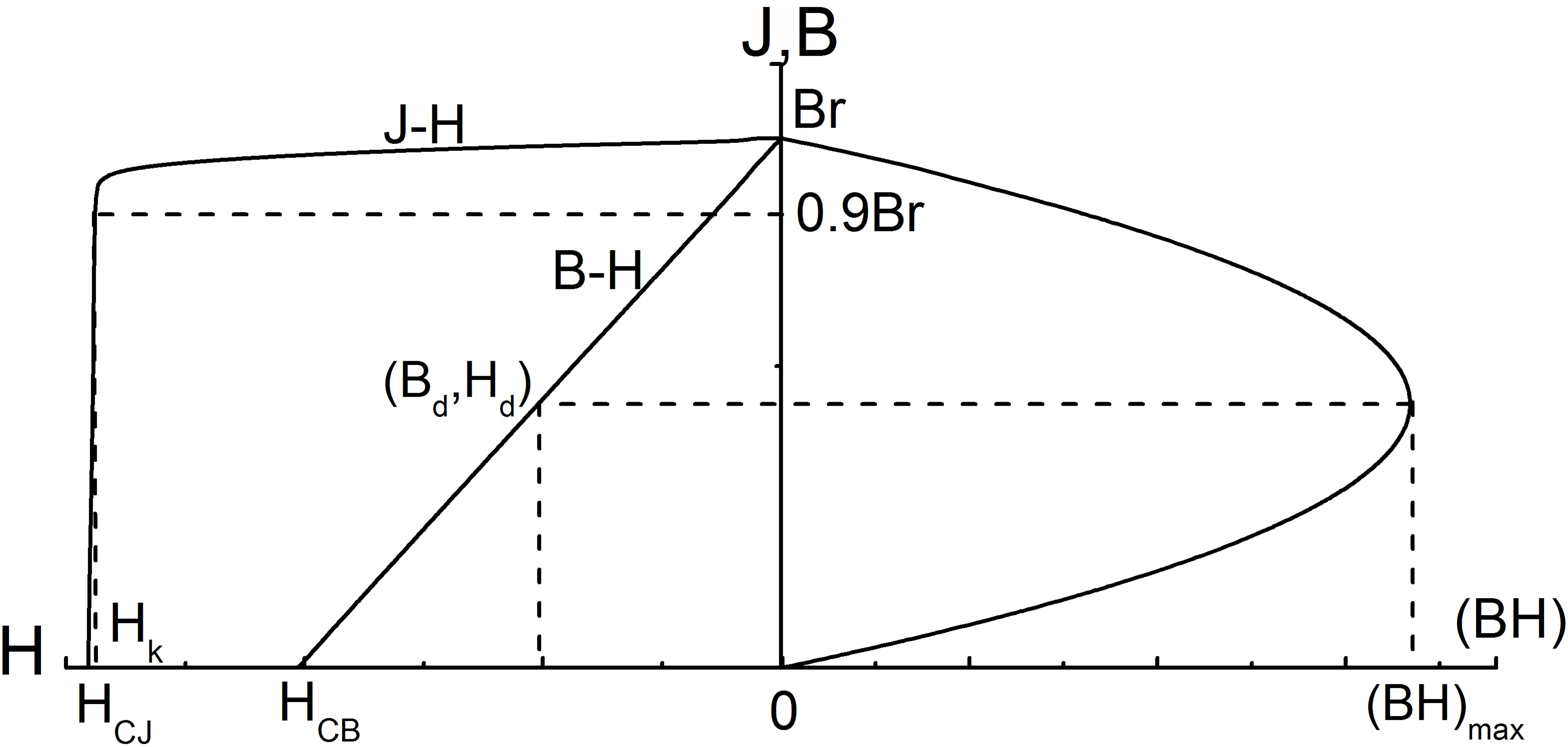
Even though magnetic measurement and electrical measurement are similar (both are based on the determination of voltages or currents), the magnetic measurements are usually more complex or even more confusing [1]. As a matter of fact important parameters ((BH)
As for the measurements of H, there are two preferred branches to determine H: direct measurements and indirect measurements [1]. In the indirect methods, H can be obtained on the basis of the Ampère law from the magnetizing current I
Totally, the magnetic properties of a material are identified as a change in (1) magnetic flux
Correspondingly, many experimental methods have been established. Though different techniques can physically exhibit intersecting areas of application, they still can be catalogued in the light of the specific effects which they are employed to reveal and measure the magnetic parameters of interest. For instance, a known experimental theory can be used, either to determine the fundamental magnetic parameters or, under a different situation, to obtain the technical characterization of magnetic materials [3].
Since magnetic properties of magnetic materials are crucial to science, technology, industry, and commerce, and are the prerequisite for any believable development in the production and trading of magnetic materials, accurate measurements are indispensable and extremely important. Therefore, hysteresis loop measurement is regularly carried out both during the improvement of magnetic materials and guaranteeing the stable quality of the final products. It is generally expected that experimental methods which are normally applied will be in a way that meaningful results can be obtained from almost any given sample. The hysteresigraph method and/or ballistic method are basically closed magnetic circuit methods, they can be used to determined the B(H) and/or J(H) curves absolutely, and by means of a appropriate calibration procedure, they all can be made traceable to the base SI units [3]. As it is impossible for most PMs to form the closed magnetic circuit, a yoke is usually employed as an alternative approach. The instrument equipped with the yoke is named the DC Hysteresigraph. The yoke can supply a near-zero reluctance return path for the flux when it has much larger cross-sectional area and higher permeability than the specimen, and then the specimen is prepared to fill exactly the gap of a electromagnet-type yoke. Using the DC Hysteresigraph, only quasi-static magnetic measurements can be performed [2]. Moreover, as a closed circuit measurement method, the DC Hysteresigraph (also known as BH Tracer) is approved by IEC 60404-5 [9], and is the predominant method used to determine the technologically important “DC magnetic properties” of hard magnetic materials. Furthermore, the DC Hysteresigraph is relatively easier to use, more compatible with computerization, and thus it is obviously easier to obtain a large quantity of data needed to draw B-H curves by programs, or even to directly show curves on screen, making this technique largely replacing the old traditional ballistic methods.
Nowadays, accurate measurement instrumentations are commercially available. Moreover, a fully computerized measurement system (perhaps with a friendly graphical user interface) is certainly a great convenience. They cannot be used as a substitute for comprehensive operator education and training, because an understanding of basic magnetic principles is crucial to success in making magnetic measurements of all types, especially in recognizing and avoiding situations that will produce erroneous results [10]. Furthermore, familiarity to magnetic materials is very important to choose proper measuring equipments and measuring conditions, and also to measure magnetic properties of magnetic film, magnetic particles (including nano-particles) and new materials. Scientists, design engineers and end users of magnetic data must be aware that not only can there be variations of magnetic properties within a manufactured product, but the magnetic measurements themselves may include a fairly large degree of uncertainty [10]. Though these phenomena are described for soft magnetic measuring in [15], they are also true for measuring PMs. The measuring principles for both kinds of materials are basically the same regarding hysteresis loop measuring, except for the ranges of applied magnetic field.
For most inexperienced users, newcomers, even to those specialists engaged in other scientific areas such as chemistry, biology, medical science, and materials science, etc. who feel much interested in magnetism in these years, suitable training in general magnetic principles, magnetic materials and testing methodology together with how to use the specific equipments which are typically provided by equipment manufacturers are very crucial. As a matter of fact, though magnetic measuring is well described in theory, the knowledge are all scattered among professional books and national standards, and only specialists engaged in magnetic measuring can be familiar with them. In addition to theories and sufficient operator training, practical skills are also very important. So in this paper, many practical problems are gathered and discussed, focused on frequently encountered problems.
As far as we know that, the method to determine the demagnetization curve of PMMs is established on the base of PMs with relatively small coercivity [2]. With the development of modern electronic techniques, it has become more and more important to measure accurately the magnetic properties of PMMs. Samples forming closed magnetic circuits, either by themselves or with the aid of yokes, as for PMs, using conventionally electromagnets to provide both the exciting field and the soft return path for the magnetic flux, offering the most accurate and practicable solution to magnetic testing of low coercivity PMMs [2]. The sought J(H) and/or B(H) correlation is obviously postulated to have a physical meaning at the macroscopic level, which means that J and/or B is a quantity resulting from spatial averaging over the definite measuring area or the cross-section area of whole test specimen. If the conditions of physical homogeneity of the samples are fulfilled, this is completely acceptable and it is what we essentially need in most applications.
The main concern in magnetic measurement is that the measured magnetic properties of the samples can stand for the magnetic properties of the magnetic materials. The hysteresigraph method is generally and frequently used for industrial testing. If the right conditions regarding sample geometry and field magnitude specified in detail in IEC [9] and ASTM [11]measuring standards are satisfied (e.g. dB/dt), one can confidently rely on the measuring accuracy and reproducibility of this method. This is an absolute measuring method and is traceable to the base SI measuring units [5, 6, 7]. With the improvement of the performance of PMMs, such as high performance RE-TM PMMs, bonded magnetic materials and nanocrystalline exchange-coupled magnet, etc., many problems have arisen in measuring their magnetic properties using traditional DC hysteresigraph methods based on lower coercivity materials, and also many new measuring methods have been proposed [3, 4], though have not been approved and covered by IEC standards yet. Every experiment method will involve its own disadvantages, and also for particular problems, there are no universal solutions. Thus, over the years, many different methods have been used to produce magnetometers. In recent years, many works have been done on soft magnetic tests [12, 13], some researches and review papers are also published on hard magnetic testing [1, 14], but few of them are specialized in industry applications, except researches on demagnetization factors [15, 16], and on effect of specimen geometry on magnetization distortion in closed-circuit magnetic measurement [17, 18, 19], which will also be discussed later.
The physical knowledge on the principal problems employed in the characterization of PMs currently adopted in research, especially in industry, including magnetic properties of material, magnetic properties of product, specimen, uniform magnetization, saturation magnetization, static measurement and dynamic measurement, the influence of the saturation of the poles, the influence of Hall probe, etc., is important in the quality control and also in the research and development of new materials. These problems are discussed in this paper qualitatively, and the methods to solve these problems are also presented and discussed, with emphasis on the underlying physical problems, the metrological implications, the normative rules and the prospective developments.
Magnetic properties of material and magnetic properties of products
As far as we know that, magnetic properties can refer to intrinsic matter properties and product properties. Magnetic properties of the matter can also be called magnetic properties of the material, which refer to the intrinsic properties that are determined by the composition, microstructure, etc. of the substance, unrelated to the shape, size of the sample, whereas magnetic properties of the product (also known as magnetic properties of sample) refer to the properties that are influenced by and also closely related to the shape, size, etc. of the sample. This can be mainly attributed to the existence of demagnetizing field. At the same applied magnetization field, if the demagnetizing field cannot be ignored, the magnetization of the material is usually higher than that of the product, because the true field the product feels will become smaller than that the material feels.
Sometimes we want to know the properties of the material, especially in scientific research, but in practical applications, we prefer to know the properties of the product. The properties given by the producer’s handbook or catalogs are usually material properties, unless special notes are given. The designers need a significant set of materials parameters to compare different materials in order to optimize their devices at reasonable cost. That is to say, these properties are all measured by standard method specified in international standard using standard specimen according to material standards. Many works have been done before the standard establishment to make the sample properties as closely as possible to the material properties, and then we can regard the sample properties as the material properties. We all know that if the sample is representative, we can get the material properties.
Practically, there should be no such term as absolute “parameters of a magnetic material” because magnetic performance is not only strongly shape dependent (e.g., due to the demagnetizing field that causes non-uniformity of magnetization and the change of parameters during the preparation of the sample), but also strongly depends on measuring speed (e.g., due to hysteresis effect, eddy current effect and other effects). Due to the demagnetizing field, practically all measured results of magnetic materials depend on the shape of the sample under test. Therefore, usually only the properties of the specimen under test are determined, but not the properties of the material. Moreover, during preparation of the specimen, to some extent, we also have changed its properties (e.g., by the process of cutting). In addition, even de-stressing by annealing sometimes cannot return the sample to exactly the same state as before the processing. Therefore, when parameters are given, it is recommended to state clearly what kind of the sample was used for the investigations (e.g., for permanent magnetic materials, samples can be in the form of bar, ring, etc. with different size). In such a case, we usually test the average parameters across sectional area of the whole sample, which is often advantageous because in this way we can take into account the possible heterogeneity in the material [1]. It is also possible to only determine the local values of the material parameters if we want to take into consideration the possible heterogeneity of the material, e.g. using relatively small sensor to determine the local parameters of individual grains [1], or measuring the sample one side after another, as in the case of hard ferrite.
The best would be the situation in which we can test exactly the same specimen as what is used in real application – such situation sometimes really occurs for ring (toroidal) sample [1], and now for most RE-TM magnets. Nevertheless, there is always a need to compare magnetic properties of various materials with assumed reproducibility – for example, if we test the same material in different laboratories.
The assumption has continued for many years that magnetic materials are reliably characterized by two main values: flux density B and magnetic field strength H. So the evaluation of magnetic materials was normally based on the relationship B
Specimen
Just as we have known that, the magnetic properties of a material can only be obtained from a closed circuit specimen such as a ring specimen. For an open circuit specimen, the test conditions, including the shape of the specimen, the measuring methods, and the test equipment, etc., must be carefully defined to achieve the material properties, and the length-to-diameter ratio L/D of the specimen must also be high enough, where L is the length of the sample along the magnetization direction, and D is the diameter of the cross-section.
It is in any case recommended that the L/D ratio of the test specimen should be larger than 1 [3]. According to IEC 60404-5 [9] and ASTM A977/A977M [11], the test specimen shall have a simple shape. The length of the test specimen shall be not less than 5 mm. The cross-sectional area of the test specimen shall be as uniform as possible throughout its length (within 1%), with smooth and as parallel as possible end faces. In a hysteresigraph, the test specimen will be inserted into the search coil and is clamped in the uniform magnetization field area between the faces of an electromagnet. For high coercivity PMM, as the magnetization and demagnetizing field become larger, the poles will become saturated, thus the uniform magnetization field area will become smaller, so the size of the specimen also needs to be adjusted, which needs to be studied further.
The hysteresigraph is suitable for samples with a constant cross-section and thickness, i.e. flat pieces, and sometimes it is a “destructive measurement” when performed on a larger or non-uniform magnet, since the sample must be cut from it, though this test will not destroy the sample during the measurement. When a test specimen is cut or fabricated from these magnets, the magnetic properties measured on it are not necessarily exactly those of the original sample, even if the material can be heat-treated again. Because the sample may not be representative of the whole magnet, the measured results may not be representative of it but just stand for the properties of the actual sample. For different samples, uniformity of composition, structure, and properties throughout the magnet volume is essential to obtain repeatable results.
For PMMs, in order to test magnetic components without machining a sample out of them (e.g., using NDT), it is necessary to work out special soft iron adapters called polar shoes, and then placed them in tight contact with both the hard magnet (the sample) and the polar faces of the electromagnet [3, 20, 21], taking care of the magnetization direction. Otherwise, if the samples have large and/or irregular cross sectional areas, or their cross sectional areas are difficult to measure, their material properties close to the sample surface might be determined instead, with the aid of the Steingroever’s concept of interchangeable polar pieces equipped with pole coils [20, 21]. In addition, for samples with a thickness of less than 5 mm, their properties can also be directly measured with a J-coil of 1 mm thickness [20, 21]. If their minimum height is thinner than 2 mm, it is expedient to stack the specimens to enough height, or if the cross-sectional area of the sample is too small compared with J-coil, two or more samples with the same height can also be put side by side in the coil, supposed that they are identical [3]. We have also found that these are good ways to get relatively useful results, and no obvious difference can be found within the accuracy.
In mass production, magnetic properties may vary between batches, within a batch, or even with a single block of magnet material [22]. So the measured results must be good enough to reflect these differences in order to insure the quality of the final products. Therefore, how samples are selected is also crucial for determining typical properties of a group of magnets. The magnets should be inspected for all specific characteristics using a statistically valid sampling plan [22].
Occasionally, some kinds of testing are especially difficult to carry out in quantity. Also, some testing is difficult due to the product shape, thus demanding some alternative test methods. A practical difficulty related to measurements on PMs with closed magnetic circuits arises from the components to be tested which have complicated shape and thus without uniform cross-section area. As these samples often dissatisfy the requirements of the Standards, also machining the specimens is difficult and costly because these magnetic materials are normally brittle, when applicable, open sample experiments can eventually be preferred occasionally, as will be discussed later. Furthermore, these alternative tests practically always require correlation testing between supplier and customer.
Both closed-circuit methods and open-circuit test methods involve known errors and corrections, and some errors are not so well understood [18]. In open-circuit measurements, the well-known source of errors are the demagnetization factor [23] and image effect [17, 18, 19, 23, 24, 25]. Open-circuit system, whose magnetic field is provided by an electromagnet with two magnetic pole pieces, such as typically in a vibrating-sample magnetometer (VSM), is subject to error from the image effect [23, 24, 25], which arises because the field produced by a magnetized sample is distorted by the presence of high-permeability pole pieces of an electromagnet.
This is called the image effect because when measurements are made in the gap of an electromagnet, the presence of large volumes of high permeability magnetic material (the pole-pieces) will distort the field surrounding the sample. That is to say, if the magnetized specimen is placed in the gap of an un-magnetized electromagnet, the lines of force from the specimen will swing around to both pole pieces. The positions they reach are just those which would result if the lines of force were connected to the “magnetic images” of the specimen in the pole pieces [28]. Theoretically, in the limiting case of a semi-infinite pole piece (like slabs) with uniform high permeability material, the effect can be described mathematically by magnetic ‘images’ of the sample existing in the pole-pieces at the mirror image positions, just like an electrostatic image in a perfect conductor. The usual result of the image effect is an apparent drop in the measured magnetization with increasing field at high fields [20, 21, 24]. At high fields, the materials of the pole-pieces will approach magnetic saturation, then their permeability will decrease towards unity, and the images will tend to disappear. Thus the calibration constants relating the magnetization of the sample to the output signal of the magnetometer will change with field. It is found that the open-circuit image effect is negligible for fields up to about 0.6 T, but at higher magnetic fields it can distort the magnetization readings by as much as 50% relative to the expected, undistorted magnetization value [25]. Though correction for the image effect is difficult since the effect depends on the size and shape of the sample, the geometry of the measuring coils and the electromagnet, and because it varies with the degree of saturation of the electromagnet pole pieces, the image effect has to be corrected by an field-dependent correction factor for the situations when the magnetization value must be accurate [24, 26]. It is also suggested that the image effect is related to saturation of the electromagnet pole-tips [26] and/or the interaction of the specimen with the electromagnet pole pieces in an open gap, suggesting the image effect will vary with the permeability of the pole-tips and so depend on the state of saturation of the electromagnet pole tip material [24, 27, 28]. When approaching magnetic saturation, the permeability of the pole tip material diminishes to a marked extent, thus causing the sensitivity of the measuring apparatus to decrease proportionately.
Closed-circuit magnetic measurements, such as those conducted in a hysteresigraph, have generally been considered to be entirely free from errors associated with the demagnetizing factor and the image effect [24], both of which can occur in open-circuit measurements. However, hysteresigraph measurements taken under closed-circuit conditions on both different magnetic materials and a range of magnetic sample geometries clamped between the pole pieces of an electromagnet show an apparent drop in the measured magnetization in the first and third quadrants with increasing applied field, similar to the image effect found in open-circuit measurements, and is called as an apparent image effect [17]. The drop in apparent magnetization caused by image effect can appear in quite low fields and can be large, approaching 50% [17]. It depends on the magnitude of saturation magnetization and on L/D ratio of the sample, and occurs for both soft magnetic materials and permanent magnets. The distortion can reduce the magnetization values as much as 42% when the applied magnetic field is 1910 kA/m (24 kOe) and the L/D is 0.28 [18].
It is found that as the saturation magnetization of the sample increases, the drop in apparent magnetization becomes greater and appears at lower fields; the effect also increases as the L/D of the sample decreases. Also, specimen geometry makes a significant difference for both the distortion field and the distortion degree in closed-circuit measurements. The magnetization distortion in closed-circuit measurements is also affected by the type of magnetic material, regardless of different sizes of the pole-tips, different shapes of the search coil, such as Nd-Fe-B with a smaller intrinsic coercivity H
In addition to the apparent decrease in measured magnetization, there is a decrease in the measured magnetic field, which is attributed to a non-uniform magnetization of the electromagnet pole pieces, where local saturation distorts the magnetic flux distribution around the sample. It is proved that for reasonably accurate (
Dependence of B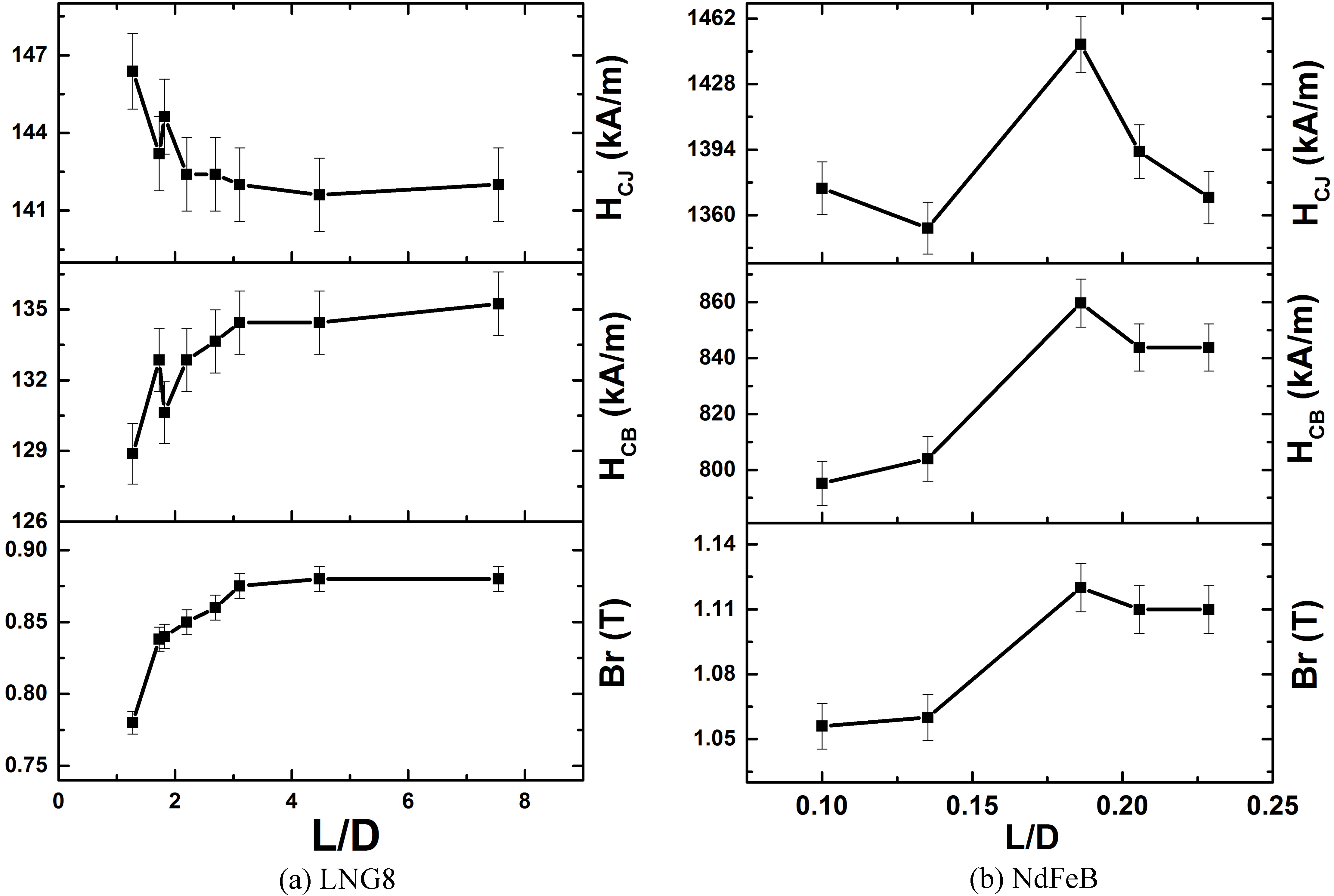
Nowadays, with the improvement of the properties, the RE-TM PMMs have been used in many different shapes and sizes, and they are mainly used at a small L/D, usually L is much smaller than 5 mm, which is the minimum length defined in standards [9, 11]. High coercive field materials also often come as short samples because the magnetic induction B behaves nearly linearly in the second quadrant loop (demagnetization curve) and the maximum energy product is obtained with a high value of the demagnetizing coefficient N (N
Comparison of NdFeB magnets with and without Ni-Cu-Ni coating.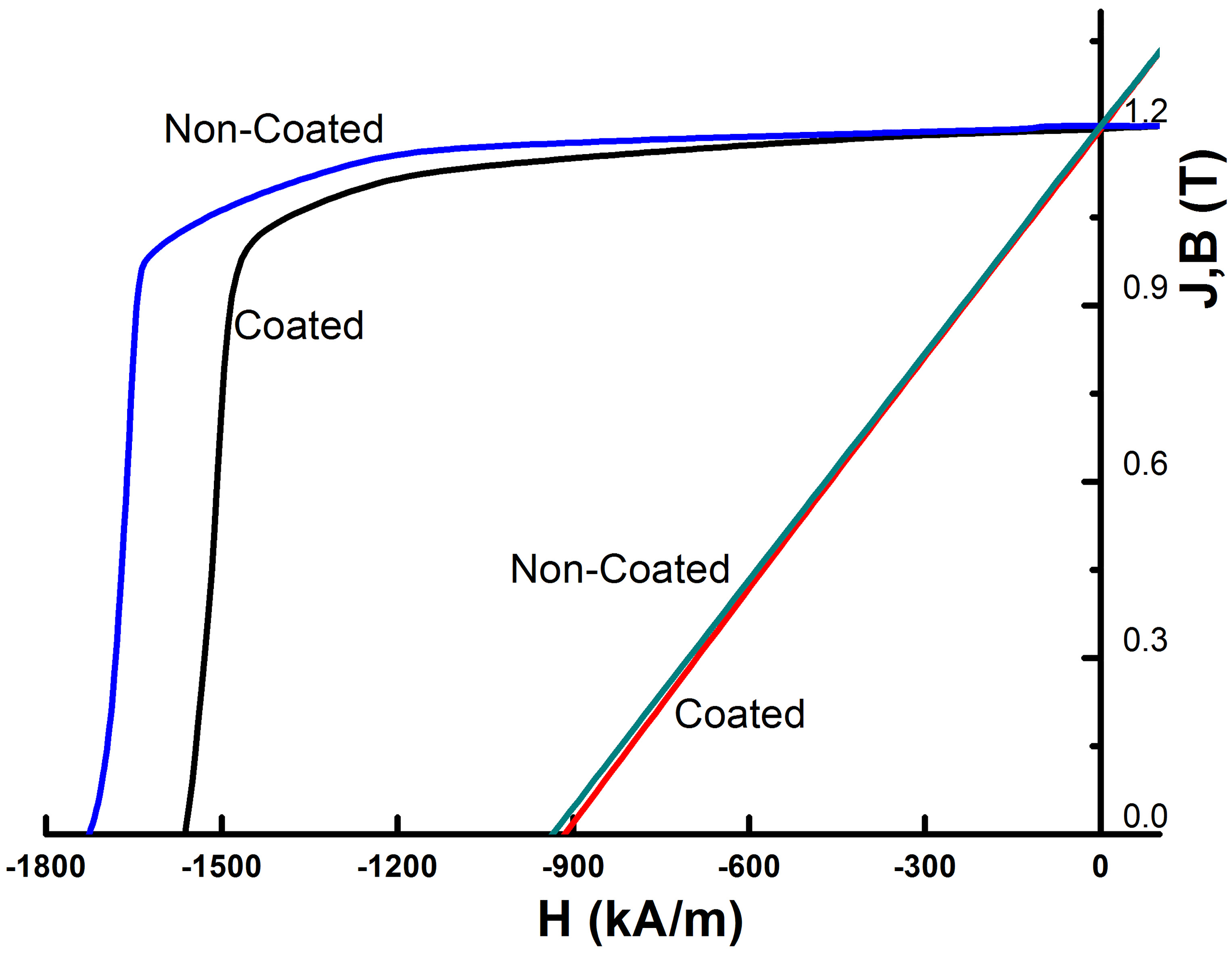
According to standards [9, 11], the test specimen can be assembled into the electromagnet and then magnetized to saturation, or can be assembled after having been magnetized to saturation in either a superconducting coil or by using a pulse magnetizer, so homogeneous magnetization of the specimen includes both magnetization to saturation before the measurement and the magnetization during the measurement.
To guarantee axial and radial field uniformity (within 1%) in the region occupied by the specimen, the diameter
where
Because demagnetizing effect is ubiquitous, the most significant problem in magnetic measurements is the role of the demagnetizing field [3]. Even in accurately closed specimens, (e.g. ring samples), one cannot get rid of them completely. In fact, the demagnetizing field is not homogeneous even with homogeneous magnetization. In addition, the demagnetizing field is also dependent on the relative permeability of the material [3]. As far as we know that, the magnetizations of the open circuit specimen are almost inhomogeneous even in a uniform magnetic field because of the existence of demagnetizing field, or the specimen should be truly ellipsoidal. Demagnetizing field can be an extremely complicated function of position for a ferromagnet of arbitrary shape, and is generally a function of position and magnetization orientation inside a sample. For an arbitrarily shaped sample, the demagnetizing field
where
If the specimen is in a given uniform magnetic field
For soft and/or hard magnetic materials, measuring the intrinsic dependence of M on H is an ideal and to a certain degree indefinable purpose because the long-range nature of the demagnetizing fields makes the behavior of any test specimen significantly related to its geometrical features. Sometimes this incorporates with unexpected existence of uncontrolled stress produced when fixing the sample in the testing fixture (e.g, yoke). Thus, practical limitations, like those related to the realization of a suitable magnetic circuit or universal acceptance of specific measuring methods by the industry, may naturally bring about the approximate realizations of the intrinsic measurements [1]. Equation (2) means that the bigger the magnetization M of the sample is, the more the field from the surface poles will oppose the external field. Thus, according to Eq. (3), for soft magnetic materials, where a relatively weak external field will lead to a large magnetization M, the internal field the sample feels can be much less than the applied field even if the shape factor N is greatly smaller than unity. Applied field and demagnetizing field can have very close values, and demagnetizing field also can be spatially nonuniform in ordinary test specimens. Thus, the precise determination of the effective field will be difficult. That’s why soft magnetic materials are rarely tested in open samples [3]. However, for PMMs, where very large external fields are required to achieve noticeable magnetization M, shape effects become important only for much smaller aspect-ratio L/D and larger N samples [23, 24, 30], and now this is often the case for high performance PMMs in modern applications.
However, a complete tensorial relationship B(H) or J(H) can be theoretically determined by simulating an infinitely long body [2]. When it is not possible or desirable to use the closed form specimen itself (e.g. with bulk rod specimens, permanent magnets), an alternative approach to form the necessary closed magnetic circuit is based on the employ of a yoke – hysteresigraph method. When H is swept slowly in the yoke, the integrator output may be recorded and a complete ‘DC’ magnetization curve and loop can be plotted in a time on the order of 1 minute.
Soft iron core electromagnets (yoke) can be the most convenient method for obtaining magnetic fields up to 3 T. The major considerations of choosing an iron core magnet as a yoke are field volume, field uniformity and field magnitude, etc. The time stability of the magnetic field H in the yoke depends strongly on the output of the power supply, and the field uniformity generally increases with increasing the pole-piece diameter. Field magnitude mainly depends on the pole size, pole shape and the output of the power supply. Furthermore, the image effect can be minimized through increasing the gap, at the expense of lower maximum magnetic field, or simply by limiting the maximum magnetic field to the values where the image effect practically keeps constant. Placing the magnetization sensor as far as possible from the pole-pieces is also helpful, but is often incompatible with placing a furnace or low-temperature vessel in the magnet gap [31].
Nevertheless, open samples can be used if higher magnetic field H is needed and/or the closed magnetic circuit is hard to use [1]. Theoretically, for open sample, we can take into consideration the demagnetizing field
When an open circuit specimen with high coercivity is magnetized in a pulse magnet or a superconducting magnet, the inner magnetic field will also be different in different positions because of N tensor. Thus, the uniformity of the magnetization field as well as the distribution of the demagnetizing field will make it very difficult to magnetize an open circuit specimen uniformly, unless the magnetization field is high enough. In addition, the specimen must be fixed firmly in the magnetizing field during the magnetization period, otherwise it will fly away.
As also can be seen from Eq. (3) that,
Usually we will have to choose open test samples in many experiments. Moreover, we will adopt ellipsoidal samples or spherical samples whenever possible, but for realistic reasons, we often have to choose cylindrical or parallelepipedic shapes.
PMMs are normally measured in closed magnetic circuits where the demagnetizing fields are kept small [24]. In recent days, high-performance PMs in large sizes are used in various products. Precision test on such magnets is strongly demanded in order to keep the qualities of the products. The problem is whether they can be measured in a hysteresigraph, or if other useful methods should be used, such as pulse field magnetometer (PFM) and superconducting magnetometer (SCM). When an open circuit specimen with high coercivity is magnetizing in a pulse magnet or a superconducting magnet, the inner magnetic field will also be different in different positions. In this case, the uniformity of the magnetization field
In practice, demagnetizing field corrections are most important at low fields, where values of permeability and remanence are determined. Demagnetizing corrections are fairly insignificant (although not small) as the sample approaches saturation. In general, values of the coercivity H
When measuring a specimen in an electromagnet, the specimen with a certain size must be placed in the uniform magnetic field area in order to be magnetized homogeneously during the measuring process. Though these conditions are all carefully defined in standards [9, 11], the whole poles or part of the poles of the electromagnet will become saturated when B
In recent days, coated high-performance permanent magnets are used in various products. Attention will also have to be paid to uniformly magnetization of such coated sample.
As the parameters important for PMMs are almost all obtained from the saturation hysteresis loops, the measured values of these parameters are very sensitive to the saturation field. Normally, the minimum saturation field H
Typical values of the magnetizing fields, H
Generally
Practically, we know that in a closed magnetic circuit,
High-quality RE-TM PMs such as Sm-Co and Nd-Fe-B exhibit room temperature anisotropy fields in the range of 5.6 MA/m (70 kOe) to 24 MA/m (300 kOe). Such high uniaxial anisotropy combined with an appropriate microstructure can lead to materials with intrinsic coercivities H
As the electromagnet in a hysteresigraph cannot produce sufficient magnetic field to fully saturate them or to bring them close to saturation, RE-TM magnets must be magnetically saturated outside the electromagnet before being inserted into the hysteresigraph [11], these have been well stated in IEC 60404-5 standard [9]. But the homogeneous magnetization of these specimens will have to be reconsidered, especially for specimens in large sizes.
For RE-TM PMMs, before testing, the test specimen with very high coercivity must be magnetized externally in a separate device which can be capable of generating higher field strengths, e.g., in the range from 2.8 to 8 MA/m (35 to 100 kOe), and then transferred in open circuit to the hysteresigraph. The direction of magnetization must be marked on the sample. Only materials having sufficiently high H
Externally magnetized specimens shall be inserted into the test-system electromagnet, such as to ensure magnetization in the same direction. In such situation, even if the specimen has been saturated, its magnetic state will stay in a certain point in its demagnetization curve as a result of the self-demagnetizing field. In order to bring it to saturation again, before measurement, the highest available forward magnetizing field shall then be re-applied before demagnetization curves are plotted [11]. According to IEC 60404-5 standard [9], when the test specimen is inserted into the search coil and assembled into the electromagnet, their magnetized direction must be towards the same direction as that previously magnetized in the superconducting coil or pulse magnetizer, and should be magnetized to saturation again. The field strength required for this can be as high as 4000 kA/m. Such a field strength is not possible in an electromagnet because of the saturation of the poles (B
It is noted that, under the relatively low values of the applied field H
This requirement relates to the magnetic hardness of such RE-TM alloys and leads to a real problem in many practical situations where magnetization fields of several thousands of kA/m are needed. In recent days, high-performance PMs in large sizes are used in various products. Precision test on such magnets is strongly demanded. In addition to the high magnetization fields needed to magnetization to saturation, large size magnets also require very high energies to reach saturation. Because in the magnetization process, energy is exchanged between the sample and the external magnetizing system, and in the period of magnetization, part of this energy is stored and part of them is dissipated in the materials [2]. Theoretically, the energy needed is roughly proportional to the product of volume and H
The magnetic viscosity (also known as the magnetic aftereffect) is the spontaneous variation of the magnetization induced by thermally activated microscopic magnetization processes (thermal fluctuation aftereffect) [3, 4, 33, 34]. It is known as the effect of delay in magnetization of the sample when the magnetic field strength is changing very rapidly, which is a statistical relaxation phenomenon in the materials due to thermal fluctuation in the non-equilibrium state. This variation is dependent on the actual magnetic state of the material (it is highest on approaching the coercivity), shows logarithmic time dependence, and enhances the magnetization change applied by the external field. The reason of this effect is rather complex and depends on the microstructure of the material.
The effect occurs in all magnetic materials. In hard magnetic materials it depends on the mechanism of coercivity – nucleation of domain walls or pinning. In some materials, it can be quite significant and can influence the coercivity. Nevertheless for the pulses of several ms used in pulsed field magnetometry, this effect is negligible [1].
Assuming negligible magnetic viscosity effects, however, the magnetic flux produced by a pulse magnet finds it hard to penetrate a whole sample in the case that the sample is a large size conductor, because the change of the magnetic fields is, in general, so fast that large eddy currents block the magnetic flux [18, 20]. The greater its conductivity and cross-section are, the less the depth magnetic field can penetrate into the magnet. Therefore, impulses of short duration can be chosen for ferrite and metal magnets with small cross-sections [20, 21]. For magnets of greater cross-sectional area, the field impulse must last longer. For metal magnets, such as RE-TM magnets, magnetizers with larger time constants than those suitable for ferrite must be chosen. This can partly compensate the field required for saturation metal-natured magnets. Though the change rate of a superconducting magnet can be easily controlled, and it can be slow enough for the magnetic flux to completely penetrate a large sample, it is very expensive and also costly. In addition, we must know that various magnetic materials will show different hysteresis effects, and thus need a variety of time constants.
The magnetization course is the macroscopic result of an extremely complex procedure of microscopic processes. The system will respond to a changing applied field H
As far as we know, when we use a traditional ballistic measurement, the magnets will experience magnetic trainings in the saturation field to make the magnetic state stable. Training is consecutive hysteresis loop measurement cycles, that is, the current will be reversed back and forth for about 10 times by means of reversing switch (to change H from
Many studies want to measure the initial magnetization curve in order to obtain the knowledge on the nature of the magnetization process (e.g., domain wall nucleation versus domain wall pinning), which demands both the specimen and the iron core (especially the pole pieces) must be fully demagnetized before measuring [2]. For the specimen, a programmed pulse field source is commonly employed to demagnetize them outside the electromagnet using a specific current wave pattern, also thermal demagnetization can also be applied, although oxidation and structural changes might be a problem with RE-TM based magnets when the magnets are heated above the Curie temperatures, especially for Sm-Co magnets.
For multi-pole magnets, as high magnetic fields are needed to fully magnetize RE-TM based magnets, even with the conventional magnetizing process employing a large amplitude magnetic pulse, this poses practical difficulties and limits the number of poles and various application requiring specific pole designs in a magnet. On investigating magnetizability of these magnets, it was concluded that magnetizing can be effectively performed at much lower magnetic fields than normally needed if the temperature of the magnet during the magnetizing process is raised and maintained within a predetermined range [35]. This optimum range of temperatures are explained as a result of thermal deterioration on the magnet’s intrinsic coercivity and remanence properties, and the limiting effect of demagnetizing field on the magnetizing process. Perhaps this is a good way to saturate high
Though it is always desirable to determine the best possible magnet properties achieved only after full saturation [11], sometimes the properties after charging to a specified less-than-saturated state have to be measured for predicting device performance. As we have known, the magnetization field is closely related to the magnetization history of the magnet. In case of magnetization of PMs from the virgin state, it may require, e.g., 4 H
The magnetic properties of a magnetic material can be categorized into static magnetic properties and dynamic magnetic properties, which is referred to the change of the magnetization slower than change of the magnetic field. The differences between static magnetic properties and dynamic properties are very large mainly because of the hysteresis effect, eddy current effect and other effects, so the measuring speed is a very serious problem. In defining and measuring the B(H) and J(H) relationship in a magnetic material, we must specify whether we will test DC or AC properties.
Now DC Hysteresigraphs are the standard and widely employed method for measuring the technologically important “DC magnetic properties” of hard magnetic materials. Strictly speaking, it is not possible to achieve the true DC characterization, because during a testing process the applied field will have to be constantly changed, in either a continuous or discontinuous way [2]. So this method should technically be regarded as a “quasi-DC-method” since the sweeping speed of the magnetization field is nonzero, but the “quasi” is normally dropped in ordinary usage.
A further concept regards certain ambiguities related to the definition of DC and rate-dependent J(H) and/or B(H) curves. The magnetization state of material is easily influenced by thermal activated microscopic magnetization reversal because of the very same metastable nature of the magnetization state that leads to hysteresis. Thus the role of thermal activation can be enhanced by lowering the field changing rate. At the same time, in bulk metallic samples it is difficult to avoid large-scale eddy current effect [2]. Furthermore, as a result of eddy currents and magnetic aftereffects, running a loop too fast can result in significant errors [11]. Therefore, in many cases, it can be understood that DC magnetization curves may be affected by extensive uncertainties and will have mediocre reproducibility [2].
When we talk about DC (or, more appropriately, quasi-static) characterization of magnets with inductive methods we suppose in acquiescence that we are exploring the J(H) relationship in such a way that time-dependent phenomena are irrelevant. Actually, in order to determine the magnetization curves, we unavoidably have to change the strength of the applied field with time. Strictly speaking, for example, when a rate-independent hysteresis loop is determined in such a way that every recorded B(H) point on the loop corresponds to an equilibrium stable microscopic configuration of the system, it can be regarded as DC curves [3]. This is only possible when the applied field is changed so slowly that the whole system is developed through successive meta-stable equilibrium states, which is to say, this change is accomplished by means of Barkhausen jumps, and becomes totally independent on the field changing rate. To some extent, this is an ideal measuring condition. However, we should be aware that conceptual and practical difficulties are frequently encountered in trying to achieve truly DC testing, because various relaxation effects can appear with time constants comparable to the measuring times due to thermally activated processes and/or eddy currents. These effects often mixed with relevant random phenomena (Barkhausen noise), which influence the accuracy and reproducibility of measurements [2], and practically make it difficult to achieve a truly rate-independent J(H) and/or B(H) behavior [3].
There are two typical ways or equally, two fundamental inductive measuring procedures to achieve the magnetization curves and hysteresis loops under quasi-static conditions [3]. (1) Ballistic method or point-by-point method: The magnetizing field strength H is varied in a step by step manner and each time the system is allowed to relax to a novel equilibrium state, afterwards, the corresponding B or J variations are determined, and the curves are achieved by a point-by-point procedure. (2) Continuous recording method or the Hysteresigraph method: The changing rate of magnetizing field dH/dt is controlled in an appropriate continuous style, as slowly as reasonable to avoid eddy current effects. Ideally, these two experimental approaches should bring about the same results, but differences can be always found because of the complicated definition of DC magnetization curve and hysteresis [2].
AC testing means to achieve or characterize a rate-dependent B(H) and/or J(H) behavior. Basically, this suggests that for a given induction rate dB/dt, the applied field strength H has to compensate for an additional opposite field related to dB/dt because of the related energy dissipation phenomena [3]. Moreover, because of high H
Generally, because the magnetic properties of PMMs are referred to the static magnetic properties, hard magnet testing is undoubtly assumed to be realized under DC conditions. When we can confidently talk of DC magnetization curves and hysteresis loops, the question of how low magnetizing frequency should be is intertwined with the problem of magnetizing rate control. Practically, time effects are often important. Even if we are seeking for quasi-static measuring conditions, their effect should accordingly be evaluated to avoid the misunderstanding in the practical recognition of rate-independent hysteresis [3]. This difficulty can be solved by enforcing a defined time dependence on the induction derivative dB/dt in the test sample by analogue means or digital means. Thus an automatic testing is always asked to be measured in a quasi-static state in order to eliminate the hysteresis effect, so measuring speed dB/dt and dH/dt must be controllable, especially at the vicinity of B
Furthermore, the time change rate of the driving magnetic field dH/dt should be sufficiently slow to avoid curve distortions on account of a delayed response of B to H change (sometimes notable), but it should also be fast enough to avoid errors caused by drifts of the instrument and integrator time constant. Often it is helpful to offer a controlled variation of the field-sweep rate in such a way that the field will change rapidly when intrinsic induction J
It is found that the measurements of the Nd-Fe-B magnets will be subjected to disturb from magnetic viscosity. This adds up to measuring a coercive field H
Influence of the saturation of the poles
The DC hysteresigraph is fundamentally a closed magnetic circuit method system equipped with an electromagnet (also called a yoke), and the test specimen is inserted into the yoke when measuring. The usual measurement of the inner field strength H
Practically, if the flux density is less than about 1 T in iron and 1.2 T in Fe-Co poles, equipotential surface can be realized [9]. But for some PMMs with high B
Nowadays B
It has been found that excellent uniformity of the field in the gap is achieved even when the value of the magnetic flux density B in the core is of the order of 1.8 T [3], quite beyond the upper limit 1.0 T recommended in the IEC [9] and ASTM Standards [11]. With optimum 54.74
When testing materials with H
Moreover, as a consequence of the apparent image effect [17, 18, 19, 23, 24], at some value of the applied field, the pole faces of the electromagnet will become locally saturated in the region adjacent to the ends of the sample, especially when L/D ratio is small. This localized saturation will lead to a non-uniform distribution of field inside and outside the sample, at the same time, the polar surfaces of the yoke are no longer equipotential. The field at the ends of a long sample is non-uniform, but near the center of the sample it will become uniform. Near the ends of the sample, the field distribution is determined by the presence of magnetized surfaces with different levels of magnetization. Away from the ends, the field will take up the configuration that can minimize its energy. The field energy per unit volume depends on H
In the measurement of magnets that have high flux density or high coercive force, the yoke poles will be located in the area of magnetic saturation, thus the field strength H
In the usual measurement of PMMs, it is assumed that the samples are homogeneous, that is to say, the samples should have constant magnetic properties throughout the volume. Moreover, the samples should have circular or other uniform cross section. In practice these conditions are not always satisfied. Errors will occur if samples have conical or otherwise non-constant cross sections and/or the magnetic values depend upon the part of the volume measured, like multi-pole magnets. Such magnets can be measured with the pole-coil method. This is a magnetic tester comprising measuring coils inserted into the surface of the pole piece of an iron yoke [20, 21]. This method can also be used to measure the demagnetization curves of inhomogeneous PMs. Furthermore, it allows the analysis of different causes of inhomogeneities, e.g., differences in the intrinsic magnetic properties within one test sample and/or both side (e.g. with hard ferrite) of a magnet, differences in the degree of orientation in a homogeneous material, differences in the effectiveness of magnetic heat and annealing treatment, differences produced by inclusion, holes or nonmagnetic contaminations, and differences produced by unequal cross sections of the tested magnet, e.g. with conical shape.
Influence of hall probe
Theoretically, methods of measurement of the magnetic field strength H widely used in industry applications mainly comprise the induction methods (including ballistic method, flux meter method, and electronic integral method, etc.) and methods based on electromagnetic effects (including Hall Effect method, magnetoresistance method, and magnetic resonance method, etc.) [3]. In standards [9, 11], it is suggested that a flat search coil, a magnetic potentiometer or a Hall probe can be used together with suitable instruments to determine H, and the magnetic flux density B is determined by integrating the voltage induced in a search coil. Usually a Hall Probe is used to measure H in a DC hysteresigraph or in a vibration sample magnetometer (VSM).
The position where the Hall sensor is placed has a great influence on the measuring results. The dimension of the magnetic field sensor and its location shall be such that it shall be within the area with a homogeneous field which is limited by the maximum diameter of the cylindrical volume defined by Eq. (2.3) in the yoke. The magnetic field strength H at the surface of the test specimen will be equal to the magnetic field strength H
Since it is not possible to directly measure the field inside the sample, if the field is essentially uniform throughout the sample and in the area surrounding the sample, the measured H can be closely representative of the H acting inside the sample. Just as described above, when the L/D ratio of the sample is smaller than 1.8, the field across the sample diameter and in the surrounding area can be extremely non-uniform due to apparent image effect [17, 18, 19, 23, 24]. More clearly, the field H is higher outside the sample than inside. So, on the whole, attempts to extrapolate from field values measured at some distance away from the sample down to the sample surface can lead to a meaningless result, since if the field is non-uniform outside the sample it will be non-uniform within the sample. Even if the field H could be measured accurately at the sample surface, the measured field would not accurately represent the field acting internally on the sample. In fact, since the field is non-uniform, it cannot be represented by a single numerical value.
It is demonstrated that the field is lowest at the center of the sample, increases with increasing radius, and continues to increase for a significant radial distance in air space outside the sample [17]. The field measured by the H probe is therefore higher than the true field at the sample surface, and much higher than the field at the sample center, thus, even though the magnetic polarization J of the sample is saturated, and therefore uniform, an erroneously higher measured value of H (higher than the true H value inside the sample) leads directly to an incorrectly lower calculated J value according to
This effect will become more notable when the sample becomes shorter, i.e., as L/D ratio decreases. Furthermore, for the sample with higher saturation magnetization Ms (also saturation polarization Js), this effect will appear at lower applied fields and the drop in apparent magnetization will become greater. This phenomenon will occur both in measuring soft and hard magnetic materials [17]. In this case an accurate determination of the field at the sample surface cannot give an accurate value of the field acting inside the sample, because there is no single value of the field acting inside the sample [17]. For a sample with L/D
Error will become larger when measuring the temperature coefficient of B
When measuring the magnetic field produced by a magnet in free space, the main drawback of the Hall probe is that the field around a magnet in free space varies rapidly as we move away from the face of the magnet, so the probe must be put directly on the face of the magnet or held at some fixed distance. Whereas the measured field clearly relates back to a magnet property, B
In practice, the relationship between Hall voltage and field H is not perfectly linear, and becomes increasingly non-linear at high magnetic fields. In this case, nominal field readings from a linear-scale meter or voltage output should be corrected. This means that generally Hall probes can be used only with control units for which they have been specifically calibrated [24]. Also they should be regularly re-calibrated [11]. Attention must also be paid to the commonly strong temperature dependence of the Hall-probe output [11].
H-coil and J-compensated surrounding coil (J-coil) (after [20]).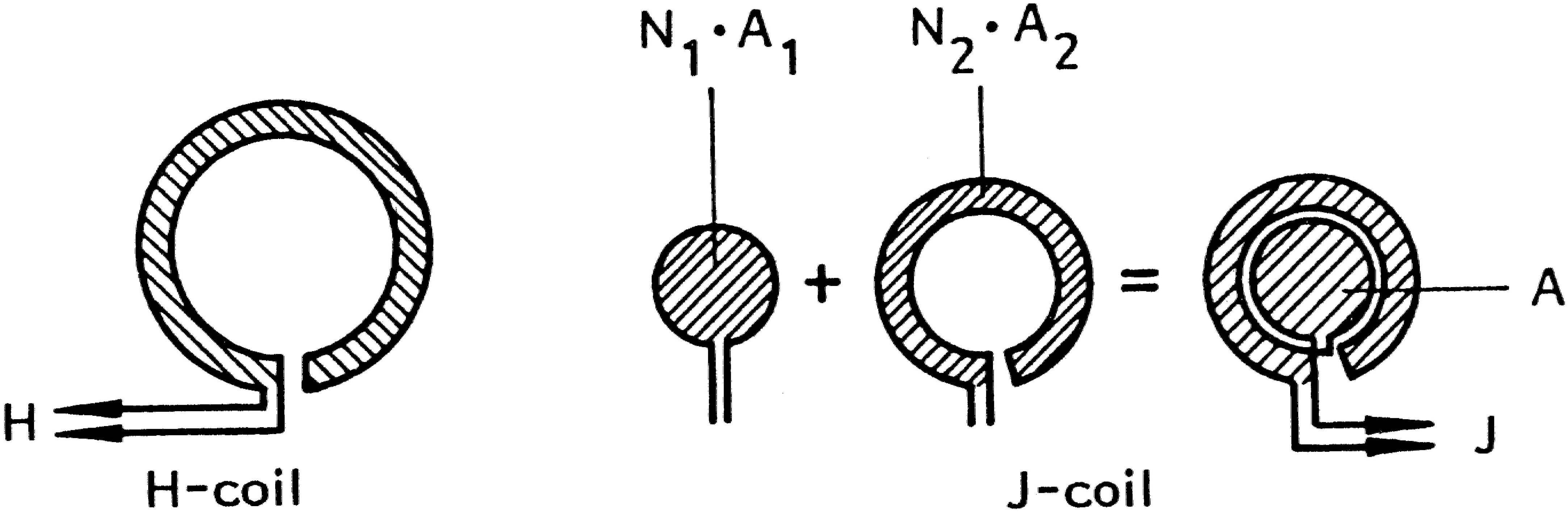
Obviously, the Hall probe will not be suitable to measure high performance PMMs, so in certain arrangements an H coil is currently used together with a B coil. A coil of known turn-area NA can be used to measure H in a given region of space [2, 31], as shown in Fig. 4. A flat H-coils, a coaxial H-coil or a Rogowski-Chattock potentiometer placed on surface of specimen can also be used for the determination of H. For high-coercivity, dense ferrites and especially for most RE-TM materials, it is essential for accurate measurement to use thin flat or radially thin annular H-sensing coils of short length (
In addition, magnetic polarization J can be measured with the aid of two co-axial coils system, one of which measures B of the sample and the other records the H next to the sample. This coil is called a J-compensated surrounding coil, also known as J-coil, as shown in Fig. 4, which is recommended by the standard IEC 60404-5 [9]. The area and number of turns of these coils is designed in such a way that the following condition is fulfilled: N
The measuring accuracy needed for PMMs is very high, and both for B and H, accuracies are within
In addition, as stated in international standards [9, 11], in order to obtain a sufficiently uniform magnetization field in the space occupied by the test specimen, some conditions shall be fulfilled simultaneously, including the diameter of a circular pole piece, the distance between the pole pieces, and the maximum diameter of the cylindrical volume with a homogeneous field, as described in Eq. (2.3). That is, the L/D value of the specimen must be strictly obeyed. To reduce the measuring error, the air-gap between the test specimen and the pole pieces shall be small. Moreover, the influence of the air-gap has been carefully considered in these standards.
Many restrictions are also stated in standards in detail [9, 11], e.g., the performance of a magnetic system can be determined by the properties of PMM, the dimensions of the system, the air-gap and other elements of the magnetic circuit. Furthermore, the methods described in these standards all refer to the measurement of the magnetic properties in a closed magnetic circuit simulating a ring core to eliminate the effect of the demagnetization effect. The closed magnetic circuit consists of an electromagnet made of soft magnetic material and the test specimen. Furthermore, to minimize the air-gap, the end faces of both pole pieces shall be ground as nearly as possible parallel to each other and as nearly as possible perpendicular to the pole axis. In addition, for certain measurements, the yoke and the poles can be laminated to decrease eddy currents. This means that the differences among the performances of different measuring systems should also be taken into account.
In order to evaluate the differences among each measuring systems including open magnetic circuit systems and closed magnetic circuit systems, PTB had organized an European intercomparison [40], from which a reasonable and reliable result was obtained, and the possible interpretations were also given. Intercomparison measurements on cylindrical specimens of Al-Ni-Co and Nd-Fe-B in a closed magnetic circuit and on spherical specimens of Nd-Fe-B in an open magnetic circuit using VSM or SQUID magnetometers show that the difference between B
In the case of Nd-Fe-B magnets additional problems result from the large temperature dependence of the magnetic properties and the dependence on the aging time due to low corrosion resistance. From this intercomparison no correlation between the results and the details of the setups used was found. In order to improve the reproducibility, it is recommended that particular attention should be paid to different measuring times and different re-magnetization processes, etc.
The DC Hysteresigraph is widely employed and is the only one commonly used for testing PMs. Though no demagnetization correction is required, the electromagnets employed cannot produce sufficient magnetic fields to saturate most high-performance magnets such as RE-TM magnets. So magnets are usually saturated first with a pulse magnetizer. Often the field is sufficient to obtain H
A different method of measurement of magnetic materials in an open magnetic circuit is defined in detail in IEC 60404-7 [41], but this standard can only apply to magnetic materials having a coercivity up to 500 kA/m, and only H
VSM method is a high-sensitivity magnetic moment measurement technique, largely applied in research and industry for the characterization of PMs. It is not an absolute method and requires calibration by means of a reference sample. In spite of widespread use, there is no IEC standard regarding the VSM technique [42].
In a recent international comparison, ten international laboratories took part in a round robin, aimed at determining the base DC magnetic properties of hard magnets using VSM [42]. Carried out in the framework of the activity of the IEC TC68 Working Group 2, the round robin was directed, in particular, at the determination of the hysteresis loop parameters of hard ferrite and magnetic tape samples in open magnetic circuit. The analysis of the results showed generally good reproducibility of measurements, comparable or better than the one observed in past experiments on rare-earth based compounds. The measurements on anisotropic ferrites show the best reproducibility for all the measured quantities, the standard deviation is around 1%. Isotropic ferrites show larger dispersion, the standard deviation of J
PMs can have significant temperature-dependent properties and thus measurements should be carried out under tightly controlled temperature [3]. For example, the coercive field in BaM and SrM ferrites has positive temperature coefficient of the order of 0.3–0.5%/
Conclusion
With the performance improvement and the wide use of PMMs, and also needs for modern electronic techniques, it has become very essential to measure accurately the magnetic properties of PMMs. Nowadays, the DC Hysteresigraph (also known as BH Tracer), which is the closed circuit method equipped with an iron-cored electromagnet and is also approved by IEC 60404-5, is mainly employed to measure their magnetic properties. Many problems arisen in measuring their magnetic properties are discussed in this paper qualitatively, including magnetic properties of material, magnetic properties of product, specimen, uniform magnetization, saturation magnetization, the influence of the saturation of the poles, and the influence of Hall probe, etc. Furthermore, new knowledge and the current status on these principal problems are also presented.
Footnotes
Acknowledgments
Many thanks to General Manager Yingyan Jia and Commercial Manager Karen Sun (Ting Sun) of Hangzhou Permanent Magnet Group Co. Ltd for sample preparation. This work is supported by 151 Fund, Analysis and Test Fund A (no. 04089) of Zhejiang province of P.R. of China.