
Abstract
In this work, a numerical method using a direct coupling algorithm is proposed for electromagneto-thermo-mechanical (EMTM) coupling analysis of structures in strong magnetic and thermal field. Both the electromagneto-mechanical (EMM) coupling effect and thermal effect are considered in the structural dynamical analysis. To realize this algorithm, a direct coupling element including degrees of freedom of displacement, temperature and electromagnetic fields is developed on the platform of the ANSYS user programmable features and verified by the comparison between the experimental data and simulation results of a typical EMTM problem. Finally, the EMTM dynamic response of a simplified model of the HL-2M vacuum vessel during plasma vertical disruption events is simulated. According to the simulation results, the EMTM coupling effect is found significant and necessary to be considered for the design and safety evaluation of Tokamak structures.
Keywords
Introduction
Tokamak devices run in a high magnetic field with huge plasma current, high confined magnetic field and high temperature. Due to the instability of plasma, plasma disruptions (PDs) may happen and the plasma vertical displacement event (VDE) is one of major type of PDs. During VDEs, not only current quench but also heat quench will happen. On one hand, huge plasma current will decrease to zero in milliseconds and huge eddy currents will be induced in the in-vessel components of Tokamak device. This is called current quench. These eddy currents interact with the high confinement magnetic field, and huge electromagnetic (EM) forces will be generated on these components. On the other hand, plasma will move downward or upward more quickly than current quench and plasma of huge heat energy will strike on the surface of components as heat flux. This is called heat quench. Meanwhile, Joule heat will also be induced in the components due to the eddy currents. Under the heat flux and Joule heat, the temperature will rise and huge thermal stress may be acted on the in-vessel components too. Thus, such huge and complex EM loads and thermal loads will act on these structures at the same time which may directly lead to material failure and configuration instability. Therefore, the electromagneto-thermo-mechanical (EMTM) coupling effect is quite important for the design and safety evaluation of Tokamak structures. The key of EMTM coupling analysis is the treatment of the electromagneto-mechanical (EMM) coupling effect and the thermal effect. The EMM coupling effect means the influence to EM field due to structural movement or deformation. Since the Team Problem 12 and 16 were proposed, many studies have been done on the EMM coupling analysis [1, 2, 3, 4, 5, 6, 7, 8, 9, 10, 11, 12, 13]. The thermal effect is the variation of material constants such as the electric conductivity and the Young’s modulus due to the temperature change [14].
The EMTM coupling is a multi-fields coupling problem that needs to be solved by using sequential coupling method or direct coupling method. Series studies have been done about EMM and EMTM coupling through conventional sequential coupling method [15, 16, 17]. However, these studies did not consider the EMM coupling effect and the thermal effect at the same time and the methods are difficult to be applied to the simulation of complex structures such as in-vessel Tokamak components. The Lagrangian method, as a sequential coupling method, is based on the governing equations for eddy current analysis of deformable bodies in Lagrangian description and staggered load transfer for simulating coupling effect [8]. It can consider both the EMM coupling effect and the thermal effect at the same time but requires a lot of computing resources and time. On the other hand, there is almost no literature dealing with the EMTM coupling analysis with the direct coupling method. In this paper, the EMTM direct coupling method was proposed at first and a direct coupling element was then developed on the ANSYS user programmable features (UPFs) platform to realize the direct coupling. The proposed method and the developed element were verified through comparing the simulation results with the experimental data. At last, the algorithm was used to simulate the dynamic EMTM coupling responses of a simplified HL-2M vacuum vessel (VV) model during the plasma VDE.
Methods
The EMTM coupling analysis consists of the calculations of three fields, i.e., EM field, thermal field and mechanical displacement field. In EM field calculation, the additional motional eddy current is introduced into the governing equations of EM field to consider the EMM coupling effect, which can be described as
where
where
For the temperature field calculation, the governing equation and boundary condition are
where
where
As for displacement field calculation, the dynamic equilibrium equation is as follows
where
where
To consider the thermal effect, the variations of the Young’s modulus and the electric conductivity due to temperature are considered by using the following relations
where
Based on the theories referred above, the governing equations of three fields are discretized at the same time by using finite element method (FEM). The discrete system of linear governing equations for the direct coupling analysis which includes all the degrees of freedom (DOFs) of three fields is as follows
where
Following the formulae above, a finite element including all the DOFs of displacement, temperature and EM field is developed on the ANSYS UPFs platform. The UserElem.F subroutine provided by ANSYS is rewritten and compiled based on the formulae above. After that, this subroutine is available to be called directly in ANSYS software as a user-defined element to fulfil the needs of the direct coupling method.
Element information
The calculation areas in EMTM coupling analysis include conductor and air area. The new developed element has 8 DOFs for conductor area, and the original element has only 3 DOFs for air area in the EM field analysis. It is worth noting that element with 20 nodes has to be chosen for treating conductor area since 8-node element is not suitable for dynamic response analysis, while SOLID 97 with 8 nodes is the only node-based element available in ANSYS for EM field analysis. To correspond the field values of the DOFs between the 8-node element in the air area and the 20-node element in the conductor area, a scheme of hybrid element was proposed, i.e., shape functions of both the 8-node and the 20-node finite elements are included in the 20-node element in conductor area. The shape functions of 20-node element are used for the discretization of displacement and temperature field and those of the 8-node element are used for EM field. As for the correspondence of the values between the temperature, displacement with 20-node element shape function and those of the EM field with 8-node element shape function in conductor area, such as EM force, joule heat and motional eddy current, the value at the middle node of each edge was set as the average of the values of the two nodes at the ends of the same edge. The information of adopted elements is shown in Table 1. In addition, at each time step, the material constants are updated according to the new temperature distribution and the relative coefficient matrices are reformed to cope with the thermal effect. In this way, a direct coupling element was developed which is suitable to simulate the EMTM coupling dynamic response problem of a structure in transient magnetic field and pulsed heat flux on the ANSYS platform.
The validity of the new element is verified through comparison of the experimental and the simulation results. As pointed above, the EMM coupling effect and thermal effect are the focus points of EMTM coupling analysis. The treatments of these two effects are verified respectively.
EMM coupling effect
Firstly the dynamic responses of the Team Problem 16 were simulated to validate the EMM coupling effect of the direct coupling element. Team Problem 16, as shown in Fig. 1, is a standard problem of simplified first wall of Tokamak device. A copper plate (0.3 mm
Material parameters of copper
Material parameters of copper
The model of team problem 16.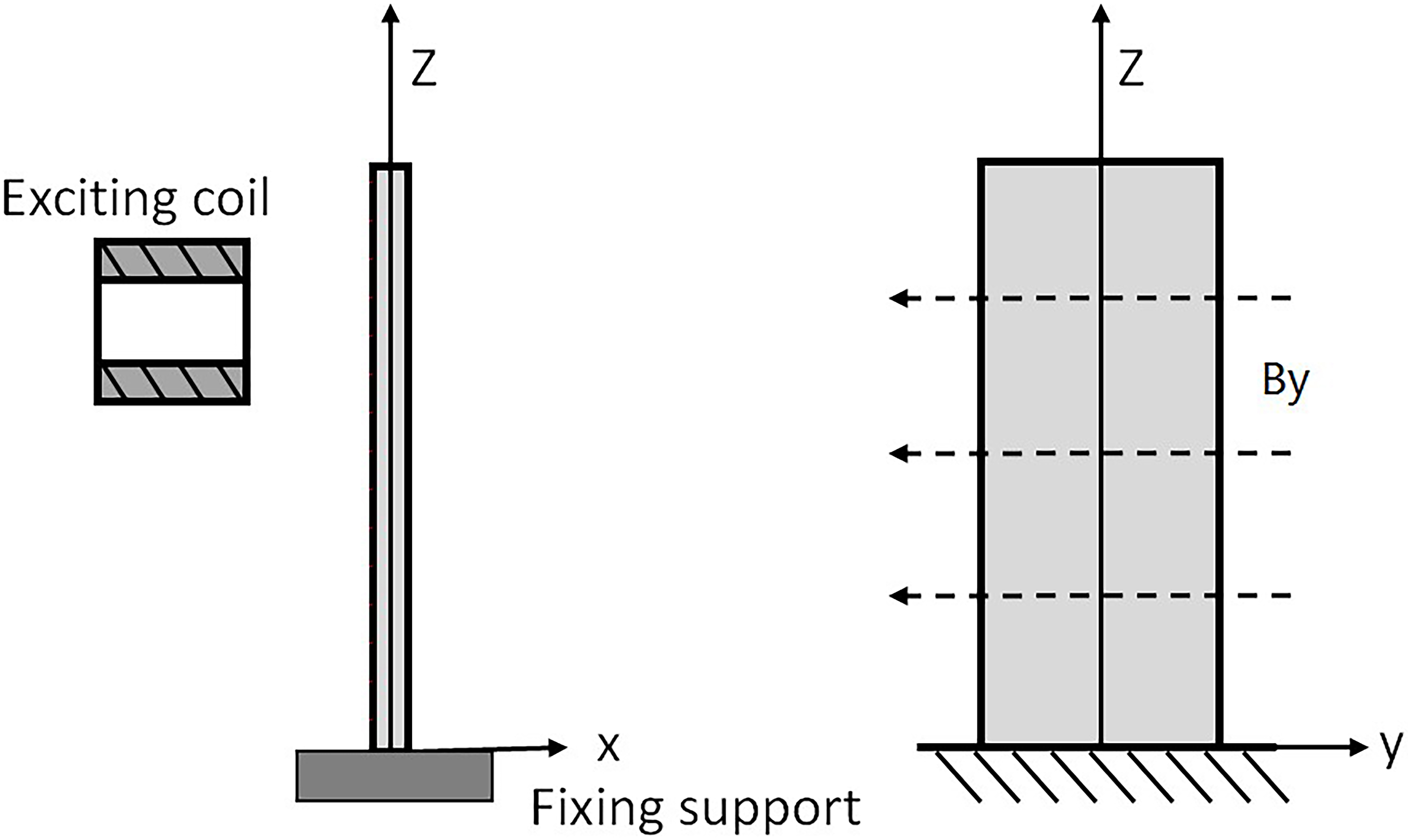
Displacements at point A. (a) By 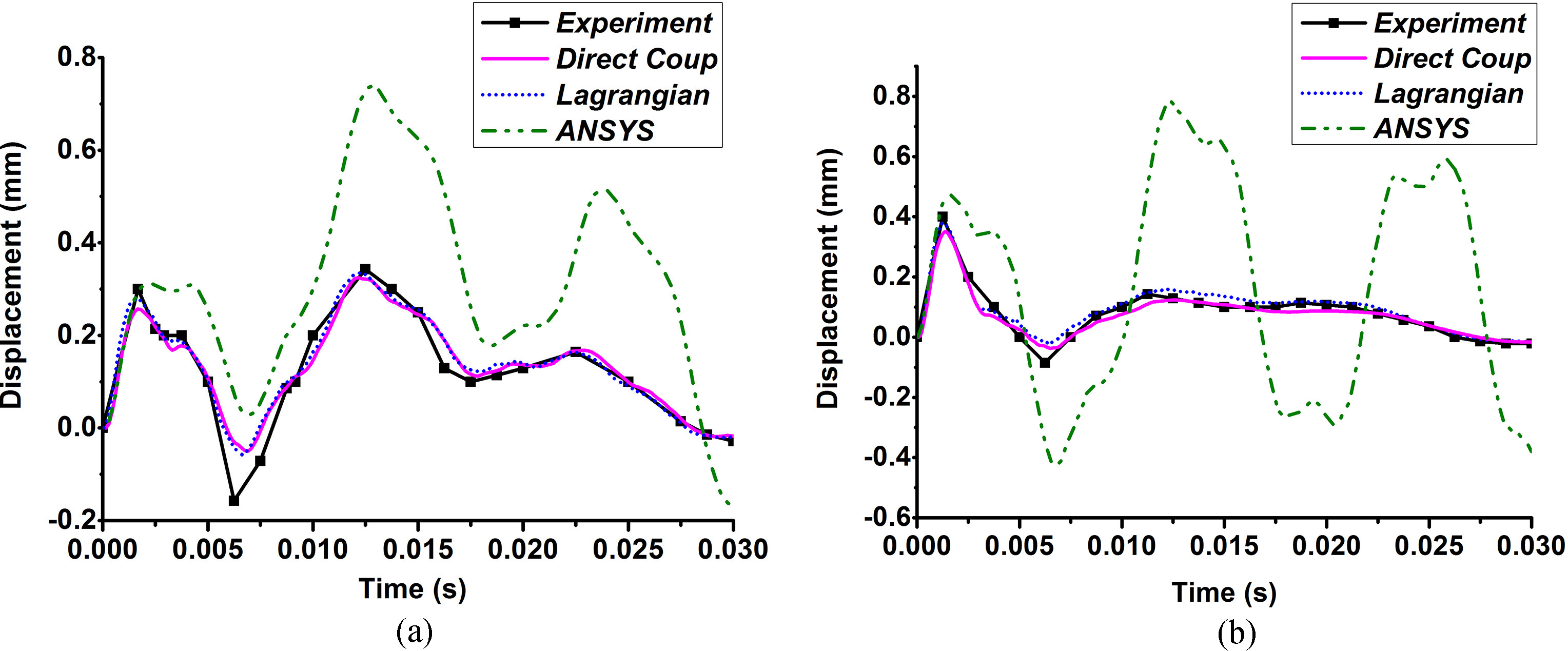
Figure 2 shows the results of point A including experiment [3], direct coupling method, Lagrangian method [8] and ANSYS without coupling with By
As for the thermal effect, a simplified EMTM coupling experiment was carried out. As shown in Fig. 3, the experimental object is a copper plate (0.3 mm
Experimental system for EMTM coupling.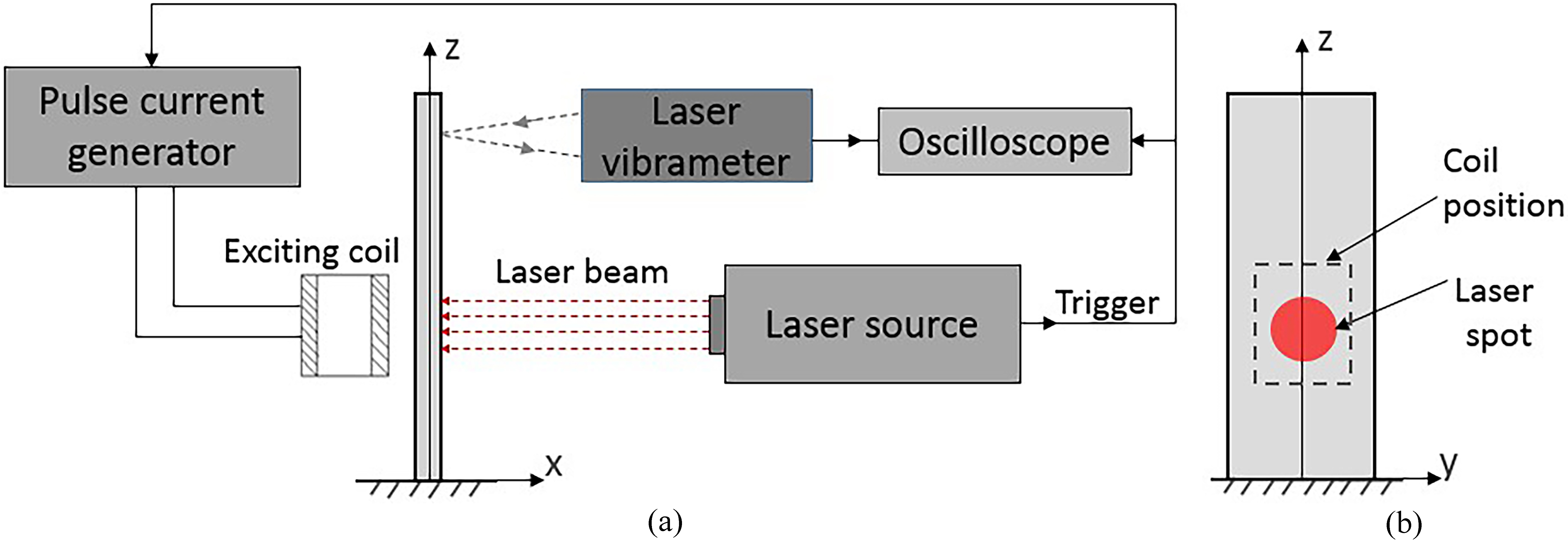
The monitored exciting current and heating power. (a) Exciting current; (b) Heating power.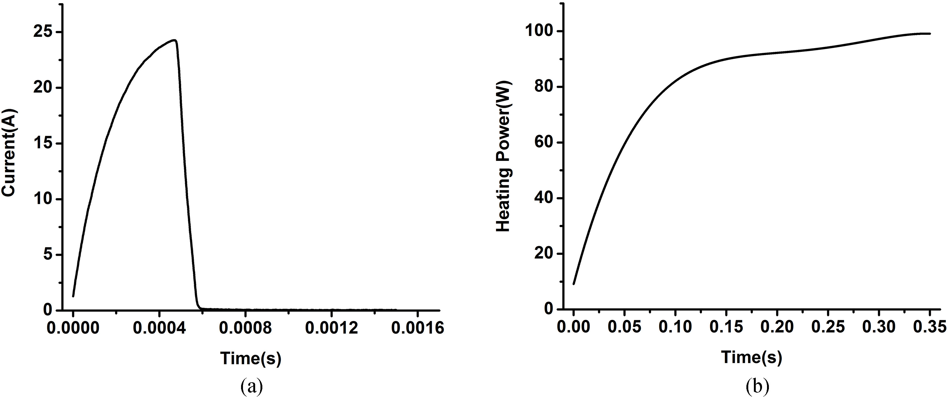
Experimental results with and without heating.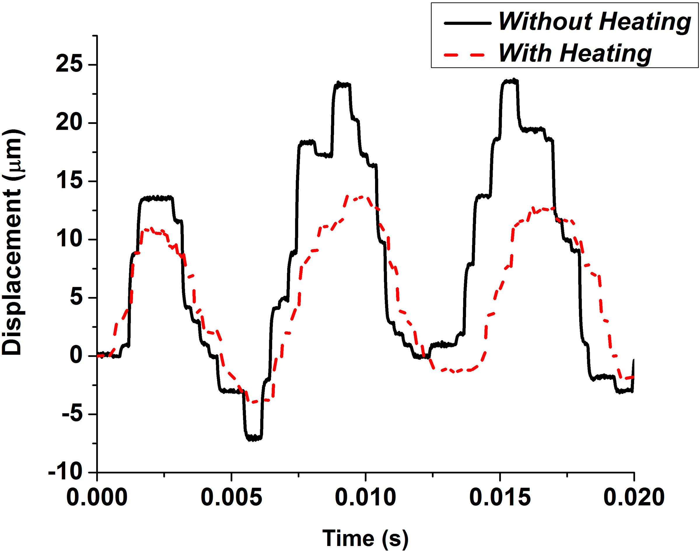
Figure 4 shows the monitored signals of exciting current monitored by the current transformer and the heating power monitored by the photoelectric sensor. As for that the heat power of laser source is 100 W and is not strong enough, the plate was preheated 2 seconds early by the heat source before the pulse current was applied to make the thermal effect more significant. Figure 5 shows the experiment results with and without heating respectively. From this figure, the displacement curve with heating has lower amplitude and longer vibration period compared with the result without heating. It can be seen that the thermal effect makes a big influence in this experiment. As for that there is no applied static magnetic field, the EMM coupling effect is not significant in this experiment.
Then the experiment progress was simulated using the developed element. Figure 6 shows the comparison of displacements obtained by experiment and simulation with and without heat respectively. Figure 6b also shows the temperature change at the centre of heating area and the maximum temperature is about 800
Above all, the comparison of the experiment and simulation results of EMM and EMTM coupling analysis proves the validity of the proposed method and developed element respectively.
To study the influence of EMTM coupling effect on safety evaluation of Tokamak device, the EMTM dynamic response of a simplified HL-2M vacuum vessel during plasma VDE with both current quench and thermal quench was simulated using the direct coupling element. Designed and under construction by the Southwestern Institute of Physics (SWIP) of China, HL-2M is a new experimental Tokamak device which can realize relative complicated divertor plasma configuration. The major design parameters of HL-2M are 2.5 MA plasma current, 2.2 T toroidal magnetic field, 5 s plasma duration time, 1.78 m major radius, 0.65 m minor radius, 14 Vs flux swing, 1.8–2.0 elongation and bigger than 0.5 triangularity [19, 20]. As shown in Fig. 7a, the VV of HL-2M is a D-shaped, double thin-wall structure consisting of inner shell, outer shell, reinforcing ribs and ports. The donuts shaped VV is 5.22 m in outer diameter, 3.02 m in height and the total wall thickness is 20 mm (the thickness of the outer shell, inner shell and the distance between the two shells are 5 mm, 5 mm and 10 mm respectively). Inconel 625 steel is chosen to be the material of the VV and material parameters of Inconel 625 steel are shown in Table 3. Besides, Fig. 2b shows the locations of coils of HL-2M including 16 poloidal field (PF) coils, 20 toroidal field (TF) coils and one centre solenoid (CS) and the initial plasma location.
Material parameters of Inconel 625
Material parameters of Inconel 625
Experimental results with and without heating. (a) Without heating; (b) With heating.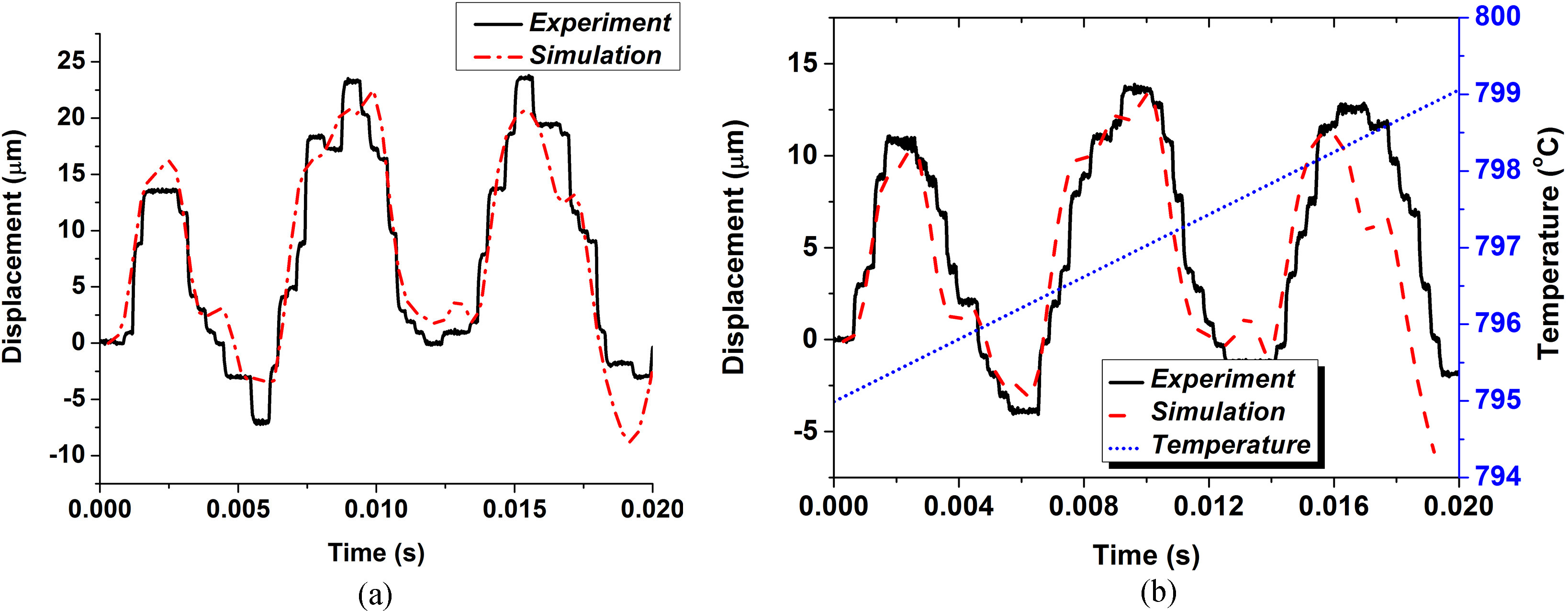
The VV of and locations of coils of HL-2M Tokamak device [21]. (a) Vacuum Vessel of the HL-2M; (b) Coil System of HL-2M.
Simplified simulation model.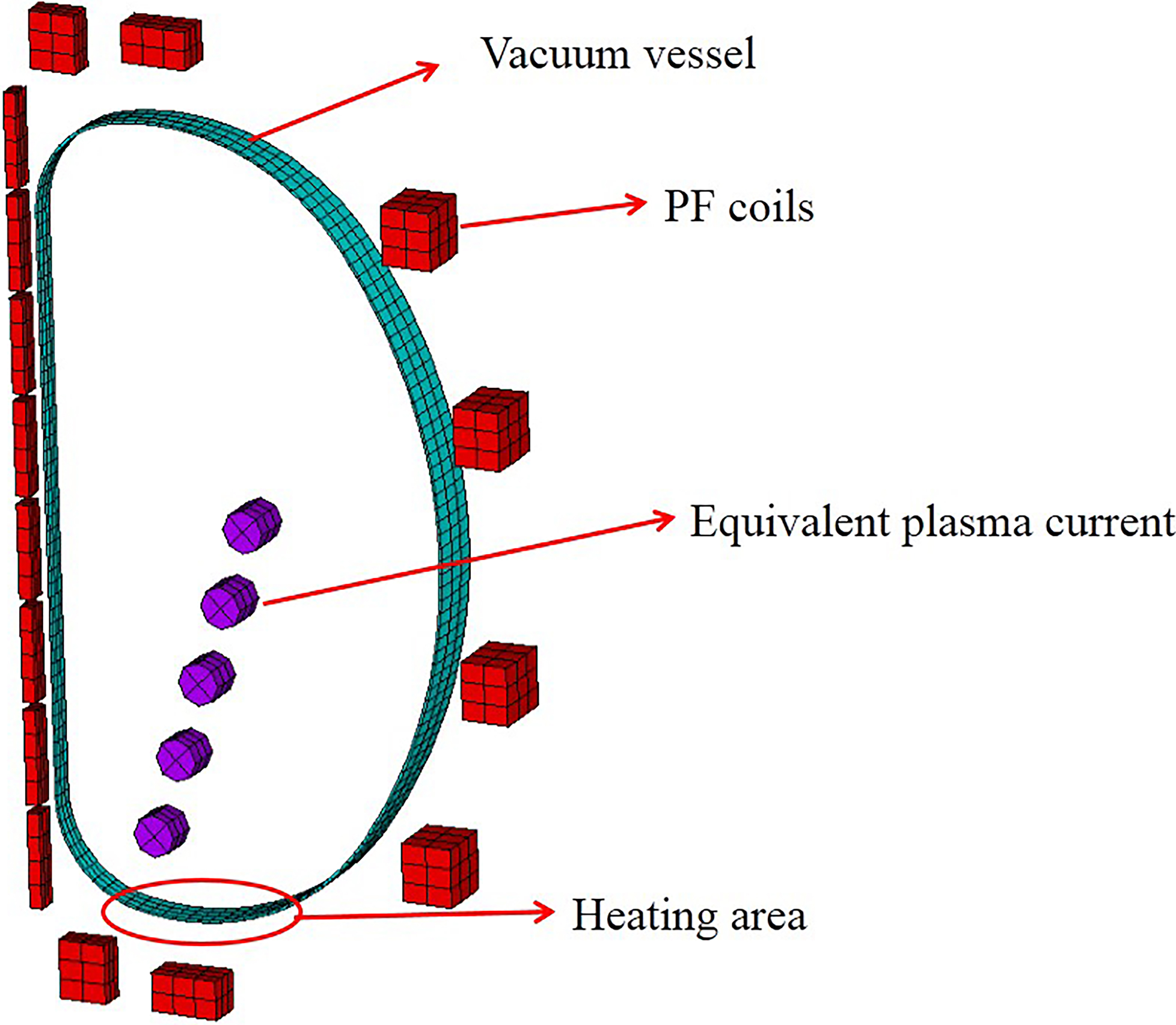
Temperature distribution at time distant 120 ms.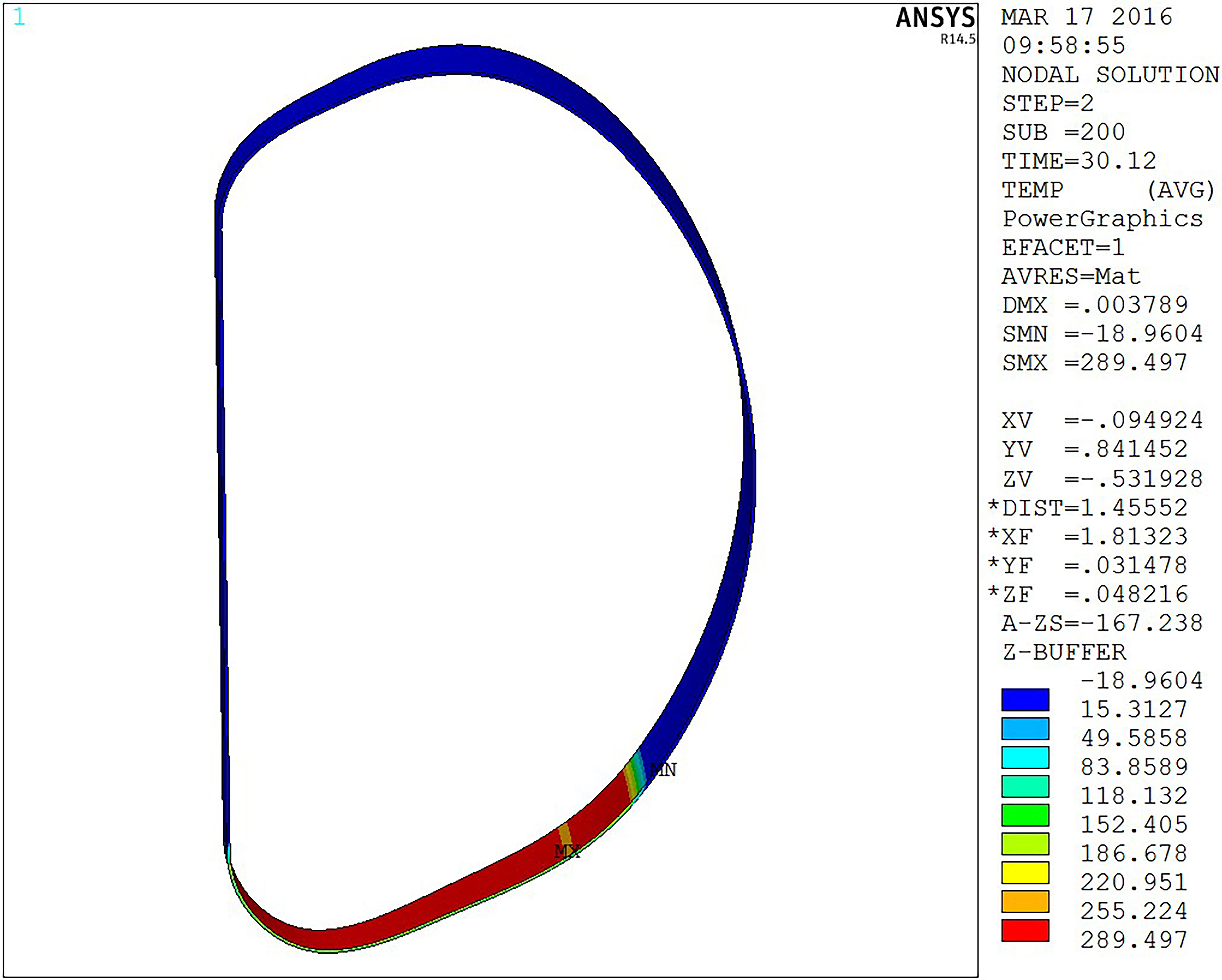
Displacement distribution at time distant 120 ms.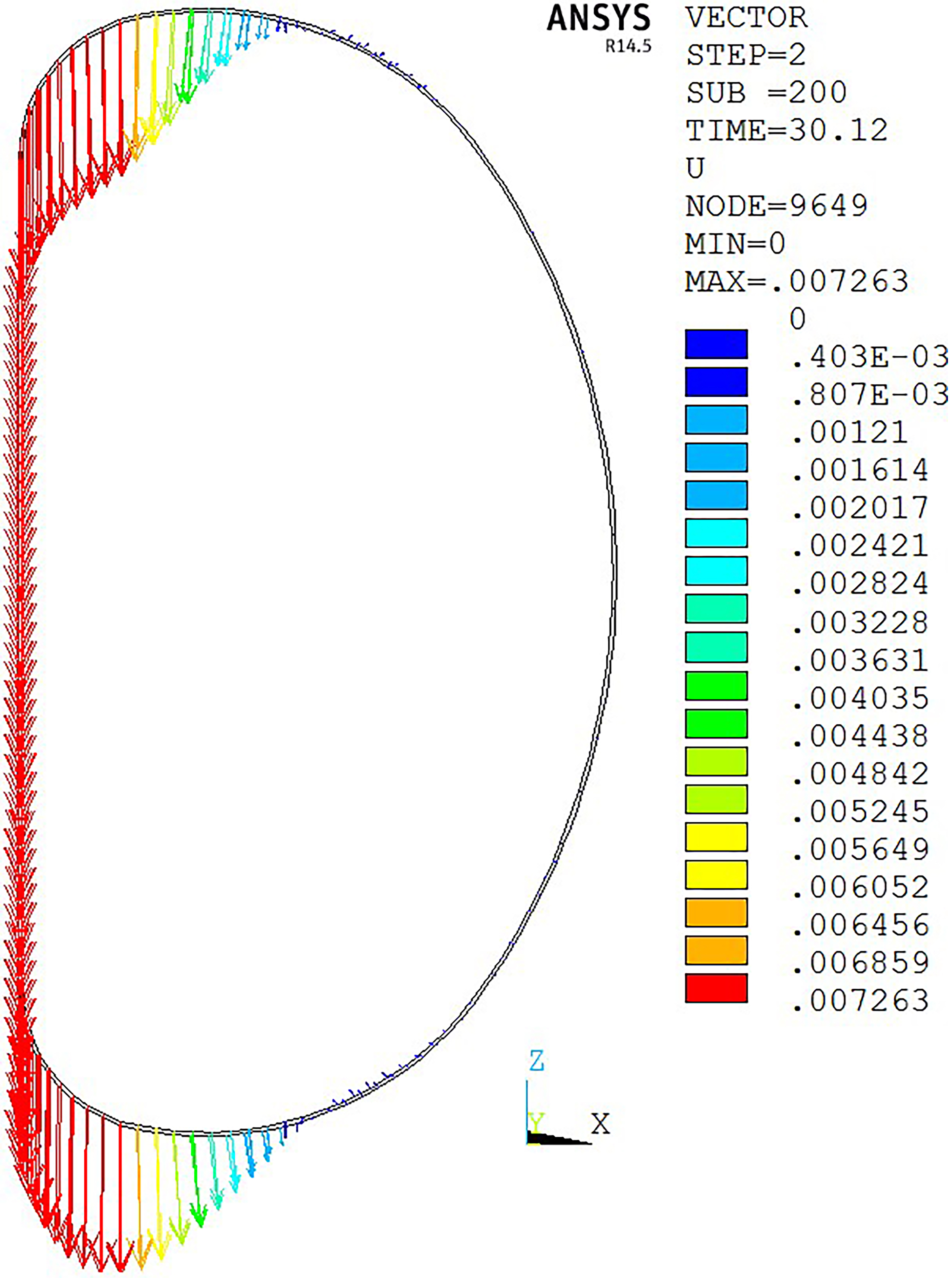
Displacements with and without considering the EMM coupling effect while considering the thermal effect.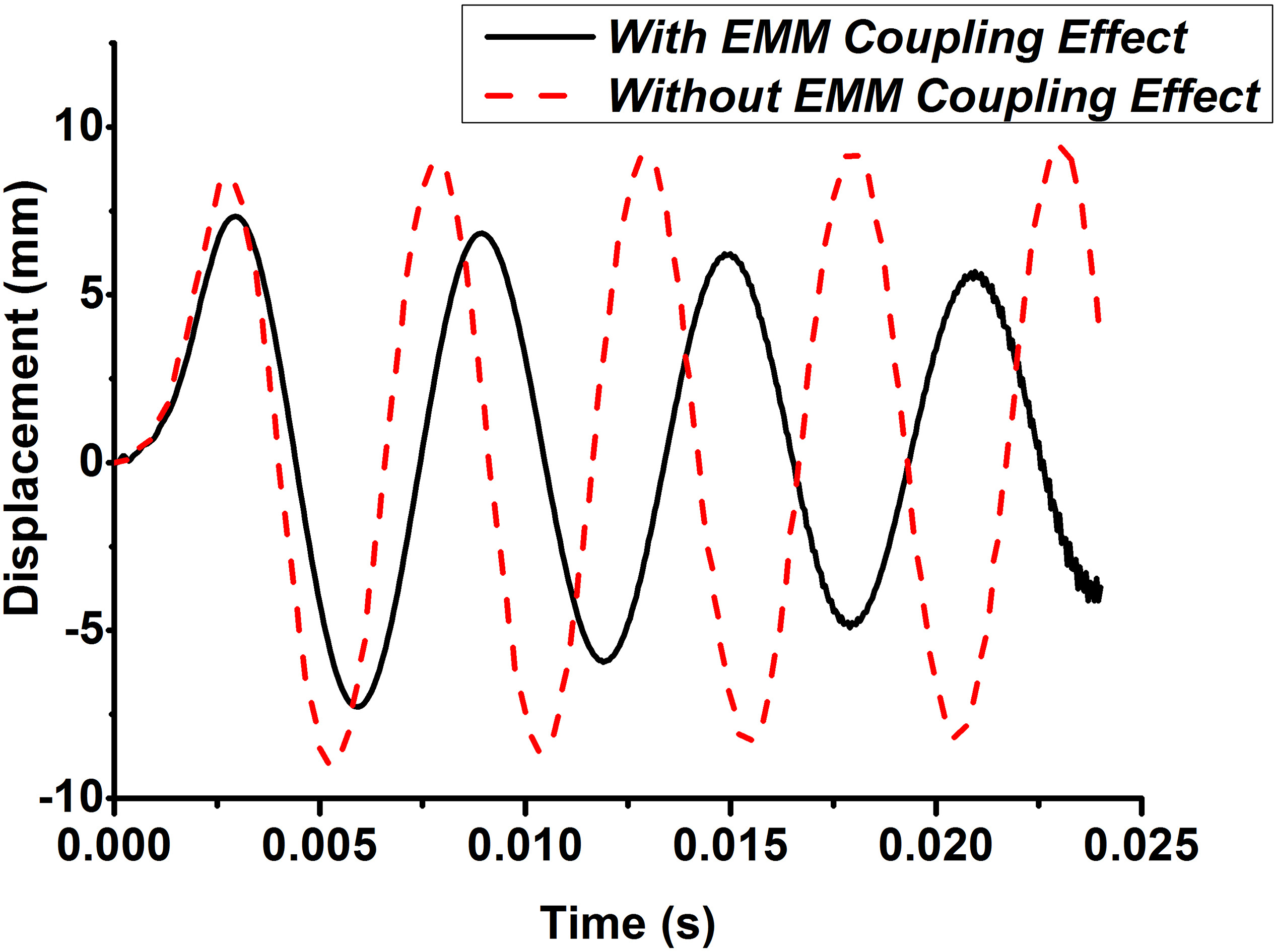
Displacements with and without considering the thermal effect while considering the EMM coupling effect.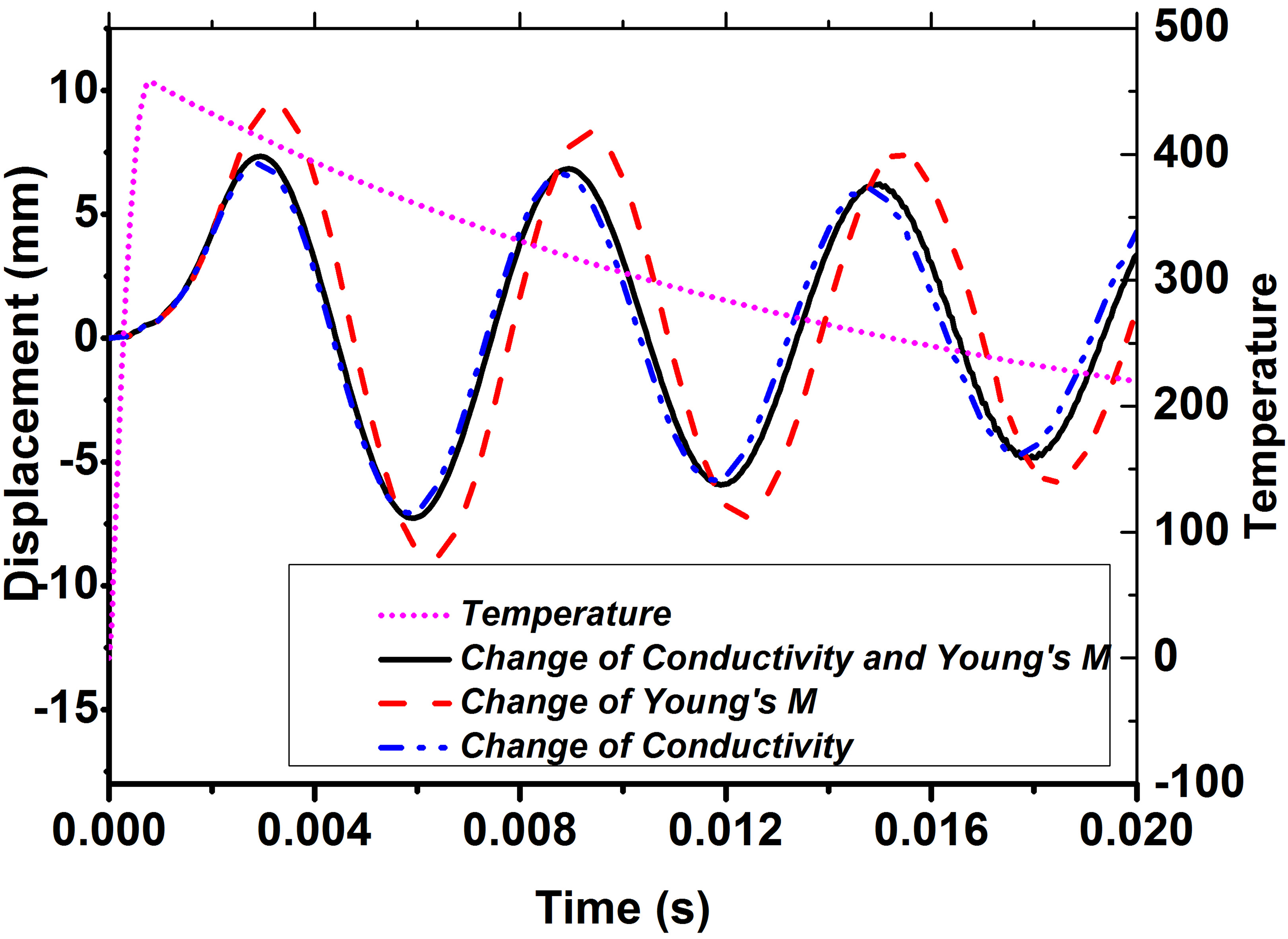
For simplification, a 5-degree model was set up consisting of VV, 16 PF coils, equivalent plasma current and air area (not shown) as shown in Fig. 8. The HL-2M VV with two-layer structures was simplified to one single layer structure which is 10 mm thick and the ports were ignored. To simulate the condition of plasma VDE, a total of 2.5 MA plasma current was set to decrease to zero in 20 milliseconds and a pulse heat flux 500 MW/m
As for the boundary condition, the cyclic symmetry boundary condition was considered on both sides of the 5 degree model. All DOFs of each pair of nodes on the 0 degree side and the 5 degree side were coupled by the “CPCYC” command of ANSYS. In addition, infinite elements were used in the outer layer of the model to simulate the infinite EM boundary. Besides, the nodes located in a small region at the middle outer surface of the VV (about 0.32
Figure 9 shows the temperature distribution at 120 milliseconds. From this figure, it can be seen that the temperature in heating area is about 290
In this paper, a direct coupling method for EMTM coupling analysis with consideration of both the EMM coupling effect and the thermal effect at the same time is proposed and a new finite element is developed on the ANSYS UPFs platform for the direct coupling analysis. The validity of the proposed numerical method and developed element are verified through comparison between numerical simulations and experiments. The advantages of less memory requirements, less computational burden and the possibility to be applied to complex structures of this method are also demonstrated through comparison. Finally, the dynamic EMTM response of a simplified model of HL-2M VV under plasma VDE with both current quench and thermal quench is simulated by using the direct coupling method. Numerical results show that the magnetic damping effect, magnetic stiffness effect and thermal effect all have a significant influence on the vibration of HL-2M VV under plasma VDE, which reveals the importance to consider the EMTM coupling effect in the structure design. The proposed direct coupling method and developed element provide a feasible approach for the design and safety evaluation of Tokamak structures.
Footnotes
Acknowledgments
The authors would like to thank the National Magnetic Confinement Fusion Program of China (2013GB113005), National Natural Science Foundation (11502192, 51577139), and Postdoctoral Science Foundation Program of China (2015M570819) for funding this study in part.