






Abstract
A permanent magnet synchronous linear motor (PMSLM) is a linear drive mechanism that converts electric energy into mechanical energy. PMLSMs have been deployed widely in modern precision industrial manufacturing. In this study, an air-gap magnetic field model of a rectangular permanent magnet array in a PMSLM is developed based on the Biol-Savart theorem and the molecular circulation model. Furthermore, an analytical expression for the magnetic field distribution of the air-gap space is derived. Ansoft and experimental measurement are used to model the PMSLM and calculate the magnetic induction intensity and validate the analytical model. The relation between the air-gap magnetic field of a PMSLM and the geometrical dimension of the permanent magnet is analyzed.
Keywords
Introduction
As manufacturing continues to develop in the current society, the demands on speed and precision in industrial production is also continuously growing. The drive and transmission mechanisms composing a conventional machine are the rotation motor, the gear, the screw nut and a connecting rod. These mechanical components experience gap, friction and wear and therefore cannot easily satisfy the stringent requirements of precision machines for precise, fast and composite positioning [1,2]. The structure required by the intermediate conversion mechanism in the conventional drive/transmission method constrains dynamic performance, volume, weight and reliability and thus cannot meet the requirements of precision industry development [3,4].
As a component of a direct drive system, a permanent magnet linear motor is a transmission device that converts electric energy directly into mechanical energy, i.e., linear motion, without any intermediate conversion mechanism. Because of their many advantages, such as simple structural design, high motion precision, rapid response, steady thrust and good reliability, permanent magnet linear motors have been widely deployed in mechanics, electronics, metallurgy, transport, aeronautics and military industries and have transformed conventional indirect drive methods [5–7]. When the conventional mechanical contact transmission mechanism is eliminated, the system structure is significantly simplified, the intermediate link-induced mechanical loss and transmission friction are eliminated, and the reliability of the system operation is guaranteed [8,9]. Because the linear motor has no rotational component, it is not affected by centrifugal force, which significantly improves the speed [10]. Therefore, the linear motor drive has a high speed and precision unachievable with a conventional drive device. It also has a higher efficiency and simpler structure than a conventional rotational motor drive mechanism and is an ideal transmission method to replace conventional transmission technology. In addition, linear motor drive technology has enormous potential and has received an increasing amount of attention in recent research [11].
Most research on permanent magnet linear motors focus on the iron core permanent magnet linear motor, whose structure is shown in Fig. 1. The stator consists of symmetric permanent magnet arrays in the upper and lower layers. Four adjacent permanent magnet blocks constitute a permanent magnet unit with a closed magnetic loop. In the diagram, g is the magnetic field air gap.
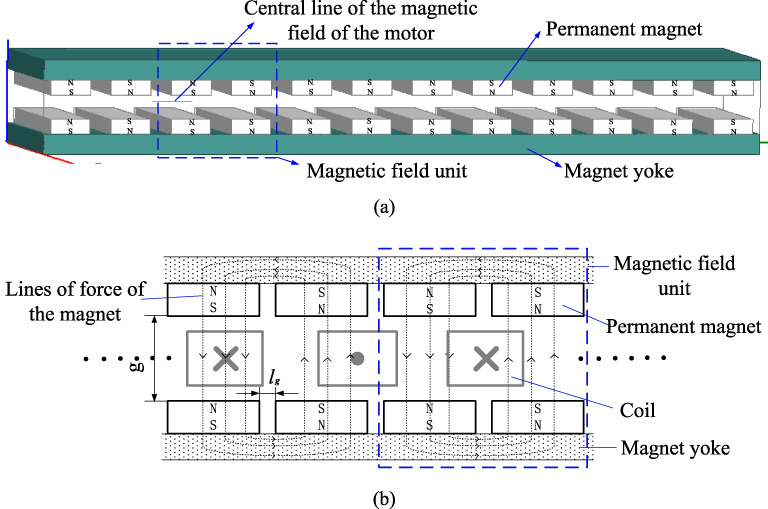
Structure of the permanent magnet in an air-cored permanent magnet linear motor (a) stator structure (b) local motor structure.
The armature winding of an air-cored permanent magnet linear motor is based on the air-cored magnetic support structure material. This design provides some advantages, such as extremely steady operation, elimination of the normal fluctuation between the rotor and the stator and extremely high positioning precision, which make it suitable for light-load high-precision linear servo systems [12–14]. Currently, studies on motors with this type of structure are scarce. The principle of the permanent magnet linear motor is to generate Lorentz forces via an electric coil in the air gap magnetic field. When the magnitude and polarity of the current in the electric coil change, the magnitude and direction of the Lorentz forces change accordingly. Therefore, research on the analytical modeling of the air-gap magnetic field in an air-cored permanent magnet linear motor is the key for better modeling and has practical value [15].
In these cases, flux leakage and magnet end flux have substantial effects on the magnetic analysis [15,16], it is critical that to build an accurate magnetic field distribution model. It is worth mentioning that some of different methods, such as numerical methods, magnetic equivalent circuit and analytical methods, have been used for modeling [17]. Among the numerical methods, finite element analysis (FEA) is widely used for field and loss evaluation in PMLSMs, however obtaining the functional form of the relationship between the magnetic field distribution and geometrical parameters of the motor is difficult [18]. Furthermore, the computational cost is enormous, but FEA can be fairly easily used for evaluation of final designs. For magnetic equivalent circuit, the accuracy of model depends on model complexity, A detailed model generally yields better results but requires increased computational effort to obtain the solution. Therefore, in most industrial and commercial motor design processes, the analytical methods possess absolute advantage [19]. It is most important and meaningful job to study the model of PMLSM with analytical methods. In [20], only the magnetic field distribution of single permanent magnet is deduced. The magnetic field distribution of multi-permanent magnet spatial array, especially the complex arrays, that the PMs are stuck on the steel-yoke with alternating polarities, is still not deduced.
The magnetic field structure of an air-cored permanent magnet linear motor shows that the distribution of the air-gap magnetic field is determined by the magnetic fields of the adjacent permanent magnet blocks. Therefore, modeling the spatial magnetic field for a single permanent magnet block with multiple interacting permanent magnet blocks in an air-cored permanent magnet linear motor is the foundation of air-gap magnetic field analysis.
Magnetic field modeling of a single permanent magnet block
As shown in Fig. 2, in the Cartesian coordinate system xyz, there is a closed wire, the electric current is I, and dl is the wire unit in the closed wire with a short tangential line.

Magnetic induction of a closed electric wire in space.
According to the Biol-Savart law, the intensity of the magnetic induction generated by an electric wire at a point P(x, y, z) in coordinate system space is as follows:
In the permanent magnet array of the stator in an air-cored permanent magnet linear motor, the overall motor magnetic field model is the combination of the local magnetic fields from multiple closed permanent magnet units, i.e., the four adjacent permanent magnet blocks in the upper and lower layers. During magnetic field modeling and analysis, the magnetic field of each unit is derived from the modeling and analysis of the magnetic field of a closed permanent magnet unit and the four adjacent permanent magnet blocks in the upper and lower layers.
In the permanent magnet array, the magnetic field intensity of the permanent magnet unit ABCD-EFGH (Fig. 3) is analyzed; point H of the permanent magnet ABCD-EFGH is set as the origin to create a Cartesian coordinate system H-xyz. A permanent magnet micro loop magnetic field unit is selected to calculate the magnetic induction intensity at point P in space, outside the permanent magnet. Based on Ampere’s molecular circulation hypothesis, a micro closed current loop A′B′C′D′A′ in the permanent magnet is selected. The magnetic induction intensity at point P in space outside the permanent magnet defined by this closed current loop is decomposed into magnetic fields at point P in space by micro currents at sections A′B′, B′C′, C′D′ and D′A′ [20]. In the diagram, a, b and h are the length, width and thickness of a single permanent magnet block, respectively.

Magnetic induction intensity at point P in space induced by a single permanent magnet block.
1. Magnetic field intensity at point P by micro current at section A′B′
According to the Biol-Savart law, the field intensity at point P induced by a current at unit width in section A′B′ is as follows:
The magnetic induction intensity in the three-dimensional Cartesian coordinate system z-direction is as follows:
The field intensity at point P induced by the current in the permanent magnet ABFE plane is as follows:
The magnetic field intensity in the z-direction is then as follows:
Similarly, the magnetic field intensities at point P induced by the micro currents at sections B′C′, C′D′ and D′A′ are obtained.
2. The magnetic field intensity at point P induced by the micro current at section B′C′ is as follows:
The magnetic field intensity at point P induced by the permanent magnet in the BCGF plane is as follows:
3. The magnetic field intensity at point P induced by the micro current at section C′D′ is as follows:
The magnetic field intensity at point P induced by the permanent magnet in the CDHG plane is as follows:
4. The magnetic field intensity at point P induced by the current at section D′A′ is as follows:
Based on the above analysis, the sum of the magnetic field intensities at a point P in space, induced by micro currents at sections A′B′, B′C′, C′D′ and D′A′ in the z-direction, is B
z−I
= B
z0 + B
z1 + B
z2 + B
z3, whose detailed expression is as follows:
Deployment of a permanent magnet array in an air-cored permanent magnet linear motor has a repetitive pattern, as shown in Fig. 1. The motor magnetic field is thus derived from modeling and analyzing the magnetic field unit. As shown in Fig. 4, the magnetic induction intensity at point P in the air-gap magnetic field of the air-cored permanent magnet linear motor is determined by superposing the four permanent magnet blocks in the magnetic field unit (the four permanent magnet blocks are marked I, II, III and IV). Among them, the calculation of the magnetic induction intensity at point P in space by the permanent magnet block I was completed via the above analysis; the permanent magnet blocks II, III, and IV are subsequently treated as spatial translations of the permanent magnet block I.
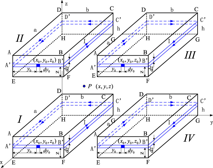
Structure of the magnetic field unit in an air-cored permanent magnet linear motor.
Similarly, the magnetic field model of a magnetic field unit is obtained based on the spatial translation of permanent magnet block I.
1. Magnetic field modeling of permanent magnet block II
Based on the translation analysis of the permanent magnet, the magnetic field of permanent magnet block II is obtained by the spatial translation of the field of permanent magnet block I along the z-axis for z
m
. Similar to the analytical calculation for permanent magnet block I, the magnetic induction intensity of permanent magnet block II at point P along the z-axis is as follows:
2. Magnetic field modeling of permanent magnet block IV
As shown in Fig. 4, the magnetic field unit of an air-cored permanent magnet linear motor for permanent magnet block IV is obtained by spatial translation of the magnetic field of permanent magnet block I for y
m
along the y-axis and switching the N-S polarity. The corresponding magnetic induction intensity at point P along the z-axis is as follows:
3. Magnetic field modeling of permanent magnet block III
Permanent magnet blocks III and IV have magnetic fields along the same direction in the xyz coordinate system, and their analysis processes are very similar. The magnetic induction intensity at point P induced by permanent magnet block III is obtained via the analytical calculation of the magnetic induction intensity induced by permanent magnet block IV. The results for permanent magnet block III is obtained by a spatial translation of the results from permanent magnet block IV along the z-axis for z
m
, as follows:
4. Magnetic induction intensity at point P from the magnetic field unit
Based on the analytical calculation of the magnetic field unit in a permanent magnet array, the magnetic induction intensity at point P in the air gap from the magnetic field unit is as follows:
Permanent magnet surface central point test
Formulae (13)–(16) are substituted into formula (17) to obtain an expression for the magnetic induction intensity at any point in the air gap in an air-cored permanent magnet linear motor. In the expression, the magnetized current density J s at the loop inner plane is an unknown variable. The magnetic induction intensity at a point in the magnetic field unit is measured and substituted into formula (17) to obtain the solution.
To measure the magnetic field unit, a magnetic field unit module is prepared, as shown in Fig. 5. The magnetic field unit is fastened with a fixing bolt in the fixation frame. The steel yoke is a magnetic conductor, whereas the fixing bolt and the fixation frame are not magnetic conductors. For easy positioning, the center of the surface of the permanent magnet block I in the magnetic field unit is selected as the measuring point. (The actual measurement is 0.736 T.) Measurements are taken with an LZ640 handheld Gaussian meter that has a measurement range of 0–2 T and a minimum resolution of 0.1 mT. Because the air gap is small and a high-precision measurement is required, an ultra-thin test probe is used that has a test range of 1.2 × 1.2 × 0.35 mm3 and a chipset sensitive area of 0.25 × 0.25 mm2.
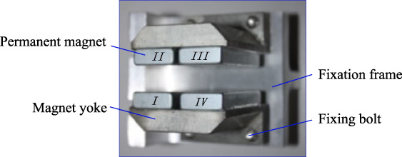
Photo of the magnetic field unit.
The motor parameters are listed in Table 1.
Motor parameters
The finite element method is used to solve various problems involving continuous variables via discretization and interpolation. This method also converts a functional equation to a multi-variable algebraic equation for solution. Therefore, many difficult mathematical problems (e.g., problems with complex boundaries and structures) become solvable. Particularly, because of the growth of computer resources, the finite element method has undergone significant development in various industries and areas, solved many complex practical engineering problems successfully and achieved excellent analytical precision [21–24]. However, finite element analysis cannot intuitively provide the relation between the motor geometrical parameters and the analysis results, thus constraining design improvement and optimization [25].
The diagram of an air-cored permanent magnet linear motor (Fig. 6) shows that the air-cored permanent magnet linear motor has no magnetic leakage at the magnetic yoke nor at magnetic saturation. Additionally, the area with the minimum air-gap magnetic flux in the permanent magnet linear synchronous motor is formed between two permanent magnet blocks in the magnetic yoke permanent magnet array, where the vertical magnetic flux density is approximately 0. In the direction opposite to the area with the minimum magnetic flux, the magnetic flux density increases gradually. Therefore, the magnetic flux density in the air gap of an air-cored permanent magnet linear motor changes following a pattern similar to a sine wave and an alternating magnetic field in the air gap is formed. That field interacts with the three-phase electric coil in the motor air gap and generates the thrust for the air-cored permanent magnet linear motor.
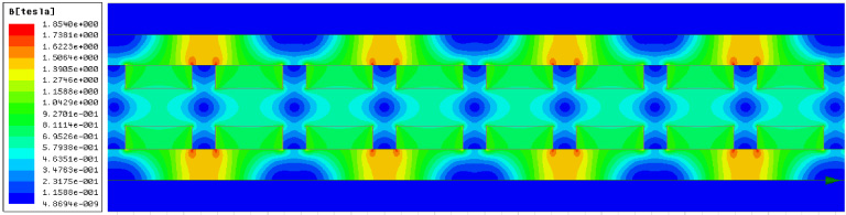
Magnetic flux density nephogram of an air-cored permanent magnet linear motor.
The magnetic lines of force (Fig. 7) and the magnetic flux density nephogram of the air-cored permanent magnet linear motor show that the magnetic field of the air-cored permanent magnet linear motor is a linear combination of the smaller magnetic fields of the four adjacent permanent magnet blocks. Therefore, research on the magnetic field of an air-cored permanent magnet linear motor can start with a small unit of four permanent magnet blocks. This approach also provides a way to decompose and simplify the modeling of the air-cored permanent magnet linear motor and its magnetic field. In addition, the validity of magnetic field unit-based magnetic field analysis for an air-cored permanent magnet linear motor is verified.
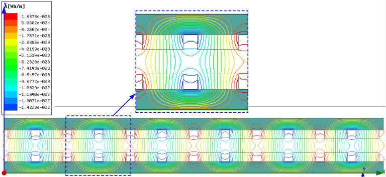
Distribution of the magnetic lines of force in an air-cored permanent magnet linear motor.
To verify the mathematical model of the magnetic field in an air-cored permanent magnet linear motor, the central line of the air gap is drawn in the air-gap magnetic field, as shown in Fig. 1(a). Because the air-gap magnetic field in the magnetic field unit is bilaterally symmetric, one side only of the air-gap central line is analyzed.
The curves shown in Fig. 8 illustrate the magnetic induction intensity versus position at the air-gap central line of the magnetic field unit in the air-cored permanent magnet linear motor, i.e., from the symmetric starting point to the symmetric end point of the air-gap central line two adjacent magnetic field units. In the diagram, “*” indicates the magnetic induction intensity at the air-gap central line from the analytical calculation, a thick line indicates the curve fit from the calculation points, and a thin solid line shows the magnetic induction intensity of the motor air-gap central line calculated from the Ansoft simulation.
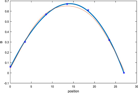
Comparison of the magnetic induction intensity at the magnetic field central line of the magnetic field unit from the analytical calculation with the Ansoft simulation.
As shown in Fig. 8, in general, the air-gap magnetic induction intensities determined from the analytical calculation and from the simulation are consistent. The maximum difference between the two is at the center of the magnetic field. The magnetic induction intensity at the center, determined from the analytical calculation, is slightly larger than that determined from the Ansoft simulation; the maximum error is approximately 0.03 T. This difference is because the weakening effect from the steel yoke of the motor on the magnetic field is not considered in the analytical calculation. The results show that the air-gap magnetic induction intensity at the right endpoint of the magnetic field unit air-gap central line is zero, and that at the left endpoint is approximately zero. This proves the validity and effectiveness of the analytical calculation.
Footnotes
Acknowledgements
The project was supported by: Yunnan Basic Research of the Applied Project: Research on Key Issues of PMSM Nonlinear Control System with Grant Number KKS0201701026.