






Abstract
Deep brain stimulation (DBS) is an effective therapy for treating neurological disorders, while magnetic resonance imaging (MRI) is a valuable method for clinical diagnosis and research. However, DBS systems in clinical MRI are under the influence of displacement force, torque and device vibration, which may be hazardous to patients after DBS implantation surgery. In this study, we evaluated these hazardous effects under 3T MRI. A set of apparatus were designed and built and the corresponding methods for safety assessment were also proposed. Results showed that the displacement force, torque and vibration of the DBS system under 3T MRI were safe. Furthermore, this study demonstrates an example of an MRI compatibility test that can be applied to many other medical instruments.
Introduction
Deep brain stimulation (DBS) is an effective therapy for treating various refractory movement disorders. A typical DBS system consists of an implantable pulse generator (IPG), a lead and an extension cable for connection (Fig. 1(a)). A series of electrical impulses of about 130 Hz are generated by the IPG. These impulses are delivered through the extension cable and reach deep brain nuclei via the lead to achieve the desired therapeutic purpose.
Magnetic resonance imaging (MRI) is commonly used for clinical diagnosis and scientific research. The combination of DBS and MRI is both valuable and promising. Unfortunately, MRI is considered to be problematic for DBS patients due to the interactions that occur between the DBS system and the magnetic fields of the MRI scanner.
The powerful static magnetic field of the MRI scanner produces a displacement force and torque on the magnetic material of the IPG of the DBS system, which may cause unwanted motion of the device and harm to patients. Moreover, the eddy current in the conductive IPG case, induced by the time-varying gradient magnetic fields during the imaging procedure, produces a magnetic moment. This magnetic moment interferes with the MRI’s static magnetic field, causing the vibration of the DBS device. The potential hazards of the vibration include device malfunction, patient discomfort and local tissue injury [1].
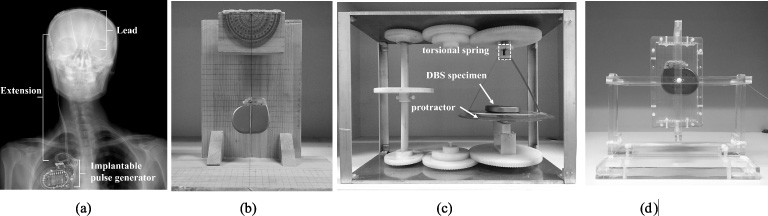
The typical structure of a DBS system (a) and the test apparatus for (b) force (c) torque and (d) vibration acceleration.
Main structure and material of the DBS specimen
For the interest of patients’ safety, international standards and technical specifications related to the MRI compatibility of implantable medical devices have been released [1–3] but a systematic safety assessment has not yet been established. In this study, we tested the most severe possible cases of displacement force, torque and vibration of a DBS device under 3T MRI and present the corresponding safety analysis.
The DBS device (G102RS, Pins Medical) tested consists of an IPG, lead and extension. The main structure and material of this device are listed in Table 1. A 3T MRI system (Philips Achieva 3.0T TX) was used to conduct all experiments. The main body of the MRI system is the scanner, which integrates the magnet and coils into one cylindrical machine as shown in Fig. 2. The direction of the main magnetic field is indicated by B 0 with an arrow. All the experiment sets were put on the patient table.

Schematic diagram of the MRI scanner and the coordinate system.
A deflection apparatus consisting of a wooden holder, a protractor and a string was built according to the standard of the American Society for Testing and Materials (ASTM) [2] (Fig. 1(b)). This was used for measuring the ratio of the magnetic displacement force to the gravity of the DBS device. The device was placed on the surface of the compliance volume of the MRI scanner, which is 0.2 m to the magnetic field centre in the radial direction at x = 0.2 m, as indicated in the coordinate system in Fig. 2. The force distribution was measured along the axial direction of the scanner from z = 0.0 m to z = 1.3 m.
Four different combinations of IPG and lead were tested: group#1: lead only, group#2: IPG only, group#3: IPG turned off with lead, group#4: IPG turned on with lead.
For the torque measurement, an ASTM torsional pendulum was constructed with torsional copper springs, nylon wheel gears and protractor, which was capable of adjusting the orientation of the DBS device in the static magnetic field of the MRI scanner (Fig. 1(c)). The specimen was located in the isocenter of the scanner (the origin of the coordinate system i.e. the centre of the magnetic field), where the maximum value of torque was expected [3].
The metal materials that may relate to these mechanical interactions can be found in Table 1.
Vibration
A customized plastic fixture with a set of nylon strings was used to provide flexible constraint to the DBS device modelling the situation in vivo (Fig. 1(d)). For vibrational strength measurements, a three-axial acceleration meter was attached on the specimen to record the vibrational acceleration and the device was placed on the surface of the compliance volume of the MRI scanner. The sensing element of the accelerometer is made from ceramics and is sealed with titanium. The mass of the sensor is 1 gram, which is quite small compared with the DBS device, so that it will not affect the vibration of the DBS device. A Fast Field Echo (FFE) MRI sequence, with a time-changing rate of the gradient field (dB/dt) of 108 T/s, was used to produce the vibration, which modelled the most severe case in clinical practice.
Different vibrational frequencies are assumed to have different importance to tissue injury, where the frequency sensitivities related to tissue injury are described by the frequency weightings [4]. The standard ISO 5349-1 documents a complicated frequency weighting cure. Here a simplified version was employed, where the actual weighting factor was approximated with 16∕f, f in which is the vibration frequency [5].
For a vibration containing multiple frequency components, which is what occurs in actual cases, a modified method for calculating the vibrational safety threshold was proposed here based on the study by Ehman et al. [5]. In this modified method, to get the weighting factor, the frequency spectrum of the vibration acceleration along each direction was firstly calculated and then summed for the combined spectrum, using their root-mean-square (RMS) vibration acceleration as their weight. Finally, the frequency weighting factor was extracted from the combined spectrum. The RMS acceleration is defined as the square root of the arithmetic mean of the squares of the time sequence of the acceleration signal in the test duration. For example, a
i
(i =1,2, …, n) is a time series of the acceleration signals, then the RMS acceleration a
RMS
is:
The combined acceleration is the square root of the sum of the square of accelerations along x-axis, y-axis and z-axis.
According to the European directive EU 2002/44/EC, the safety limit of the RMS vibration acceleration for an 8-hour period is 5 m/s2 and 1.15 m/s2 for hand-transmitted vibration and whole-body vibration, respectively [6]. Given these safety limits, we calculated the equivalent safety vibration acceleration threshold for a certain vibration duration using our proposed modified method, as shown in Eq. (2),
The worst-case values of all the test results are listed in Table 2.
The test results of force, torque and the frequency spectrum of vibration are shown in Fig. 2. The maximum force appeared at the entrance of the scanner hole which was about 1.0 m to the isocenter, where z = 1.0 m, as shown in Fig. 3(a). The most severe case of displacement force was about 46% of the gravity of the DBS device. The safety criterion by ASTM standard states that displacement force no larger than the devic’s gravity can be considered to be safe [2], suggesting the magnetic displacement force of the DBS device under 3T MRI was safe.
It has been proved that the value of the displacement force is proportional to the spatial gradient of the static magnetic field [2]. The largest spatial gradient generally appears at the entrance of the MRI scanner, where the largest force was also observed in the test, suggesting that our result was reasonable.
The lead itself had little magnetic force because it is made from platinum–iridium alloy, which has little magnetism. Another result was that the status of the IPG had little impact on the force. As we know, the lead carrying current in a magnetic field may experience Ampere force. In the DBS system, the typical current in the lead is 3 mA and the total length of lead and extension is 1.0 m. The resulting theoretical maximum Ampere force in a 3T magnetic field will be 9 mN, which accounts for only 2.4% of the device gravity. Therefore, the IPG status (turned on or off) played an unimportant role in the force test.
Test results of the potential hazardous effect
Test results of the potential hazardous effect
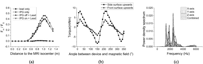
The test results of the (a) displacement force (b) torque and (c) frequency spectrum of the vibration acceleration.
The torque was tested with the IPG side surface facing upwards and front surface facing upwards. For these tests, the device was turned off. As shown in Fig. 3(b), the maximum torque was 8 mN ⋅ m, smaller than the gravity torque of IPG, which was 22 mN ⋅ m, meaning that the torque was safe according to the ASTM standard [3].
If the lead with current forms a loop, it will produce a torque in the magnetic field, and the maximum value can be calculated as shown in Eq. (3) [3]:
In the vibration test, the frequency spectrum is shown in Fig. 3(c), and the RMS of combined vibration acceleration was 52.4 m/s2. To calculate the safety threshold, the safety limit was set as in the European directive A lim = 1.15 m/s2, the vibration duration T = 0.5 h,which is a reasonable worst case in the clinic [7]. The resulting frequency-weighted equivalent vibration safety threshold was 693.8 m/s2. According to the physical process of the vibration, the vibration acceleration is proportional to the rate of changing of the gradient magnetic field dB/dt [1]. The dB/dt used in the test was 108 T/s and the maximum dB/dt of the commercial 3T MRI scanner is 200 T/s. Therefore, the vibration acceleration in our test can be scaled up to the maximum value for all situations, which is 97 m/s2, smaller than the threshold. This result suggested that the vibration of the DBS device under 3T MRI was within the safety margin.
In this paper, our research focused on the hazardous effects including displacement force, torque and vibration of DBS device under 3T MRI fields. A set of test apparatus were designed and built for measuring the above safety-related parameters and a modified method for vibration evaluation was presented. Finally, the MRI safety of DBS systems were assessed, demonstrating that the displacement force, torque and vibration were safe for DBS patients.
This study established a testing platform for safety and provides an example for an MRI compatibility test. The presented methods can be extended to evaluate other medical devices and instruments such as pacemakers, stents, and orthopaedic implants.
Footnotes
Acknowledgements
This study is supported by the National Natural Science Foundation of China (No. 51407103), the Major Achievements Transformation Project of Beijing’s College, the National Key Research and Development Program of China (No. 2016YFC0105502), the Tsinghua University Initiative Scientific Research Program and the National Natural Science Foundation of China (No. 51777115).