






Abstract
In view of the bearing current of motor, a method of suppressing the bearing current using the field emission characteristics of carbon nanotubes is proposed. Firstly, the advantages of carbon nano-materials and their field emission properties are introduced. Secondly, the influence of the distance between the emitter tips and the anode metal plate on the electric field intensity is analyzed by software simulation. Finally, field emission experiments of TNF300 type carbon nanotube fibers under non vacuum conditions were carried out by means of probes, microscopes and other experimental equipment. After obtaining the voltage and current of carbon nano-materials at different distances, the volt-ampere characteristic curves and the field emission characteristic curve were drawn, and the experimental results from different distances were compared and analyzed.
Introduction
With the application of PWM variable frequency speed control technology in the motor drive system, the negative effects of variable frequency speed regulation system is gradually emerging. One of the typical negative effects is the high-frequency bearing current caused by common mode voltage.
The electrostatic charge generated on the shaft on which the motor operates is gradually accumulated, so that the potential of the bearing voltage is continuously increased due to charging. If the voltage exceeds the insulation strength of the bearing oil film, the charge will be discharged in a very short time to form a bearing current [1]. The lump parameters common mode equivalent circuit is shown in Fig. 1, among them, Crf is rotor-to-casing capacitance, Cwf is stator-winding casing capacitance, and Cwr is stator-winding rotor capacitance. Cb1 and Cb2 are bearing capacitors, and Ib1 and Ib2 are drive current and non-drive end bearing currents respectively.
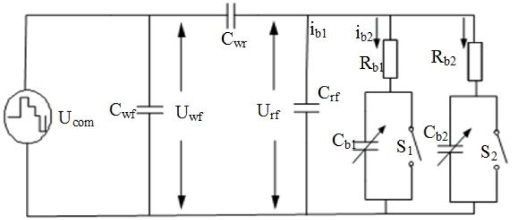
Lumped parameters common mode equivalent circuit.
The research shows that 40% of the motor faults are caused by bearing damage, and 25% of the motor bearing damage is caused by the inverter bearing current. The electrical corrosion of motor bearings is shown in Fig. 2 [2,3].
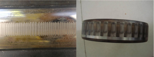
The electrical corrosion of bearing surface.
For the bearing current problem, the long-standing method is to install the brush at both ends of the bearing and guide the bearing current through the brush; or insert the metal foil in the air gap of the motor, and ensure that the metal foils is insulated from the iron core and grounded. This can effectively prevent the generation of the bearing current. However, motor bearings may still be damaged due to poor insulation caused by foreign bodies of lubricating oil. In another method, the grounding brush has material wear problems after a long period of operation, resulting in poor contact and electrical corrosion [4,5].
To solve this problem, a new method of changing the current path of the bearing is proposed, which utilizes the non-contact characteristics of carbon nanomaterial field emission to eliminate the bearing current.
Carbon nanotubes(also known as Bucky tubes), are a new type of carbon structure discovered by Dr. Iijima Sumio, Japanese Electronics Company in 1991 [6]. Carbon nanotubes mainly consist of hexagonal carbon atoms and form coaxial tubes of several layers to several tens layers. The layer spacing is fixed at about 0.34 nm, and the diameter is generally 2 ∼ 20 nm. And according to the different orientations of the carbon hexagon along the axial direction, they can be divided into three types: zigzag, armchair and spiral.
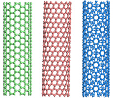
Three types of SWNTs.
The electronic band structure of carbon nanotubes is special, and has a one-dimensional Brillouin zone. The electrons are not restricted in axial motion, and the quantum effect is obvious. It has high emission field with low emission threshold, high emission current density and high field stability.
Regarding the suppression of bearing current using carbon nanotube materials, this is a preliminary idea, so the experiment is still in the preliminary preparation stage. The experiments and simulations in this paper appear to be independent of the suppression of bearing current. In fact, almost all field emission experiments are carried out in a vacuum, and the environment in which the motor works is mainly in the air. Therefore, this experiment aims to explore the field emission characteristics of carbon nanotubes under non-vacuum conditions. In the subsequent experimental exploration, we will further study the conditions of different vacuum degrees and the effects of different materials on the field emission, and apply them to the motor bearings to suppress the bearing current of the motor.
As for the installation of carbon nano-materials inside the motor, we assume that the carbon nanotube fiber cluster is fixed on the fixed ring of the motor, and the anode metal surface is fixed on the rotor of the motor, so that there is no mechanical contact between them. When the motor is in operation, the carbon nanotube fiber clusters will release the common-mode parasitic electrical energy to the anode metal surface and protect the bearings and other parts of the motor (as shown in Fig. 4).
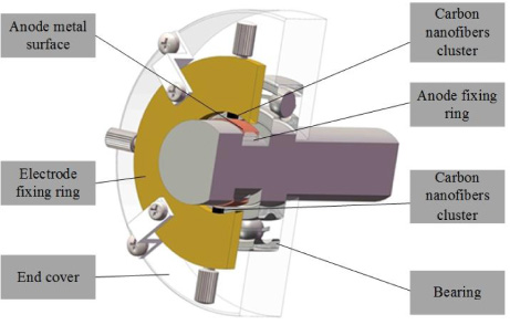
Schematic diagram of installation of carbon nanotube fiber cluster electrode ring.
The field emission of free electrons in a conductor is the basis of the space energy transmission of the non-contact state. All of the atoms inside the emitting material contain a large amount of electrons, but in general, these electrons are bound inside the object and present a very stable state. However, when sufficient energy is applied externally, these electrons break away from the nucleus’s bound and are released from the surface of the object.
The principle of field emission is to reduce the barrier energy height and shorten the width of barrier by applying a strong electric field applied to the material. As a result, a large amount of electrons in the material can escape from the barrier of the material surface, thus completing the electron emission process.
In 1928, Fowler and Nordheim used free electron theory, tunneling theory, current density, work function and electric field intensity of metal surface to make a series of hypotheses on field-induced electron emission [7,8]. They put forward the following assumptions:
Consider a band of electrons and its distribution agrees with Fermi Dirac statistics; The surface of a metal is regarded as a smooth surface, regardless of its atomic scale; There is a charge of the mirror force; The distribution of the work function is very well-distributed.
Then the quantitative expression of the Fowler Nordheim equation was derived for the first time, the field emission current density formula is derived, which is generally called the F-N formula:
Among them 𝜙 is the work function of the emitter [9,10].
From the above theory, the work function and the electric field strength is the main factors affecting the intensity of electron field emission, and the material properties of the work are not easy to change. Therefore, the key of launching electrons inside the body to break through the barrier surface and realize the electron field emission lies in the electric field intensity of the environment. Besides, the shape of the material is known to strongly affect the field emission [11,12].
Through the field emission theory, we know that the current density of field emission is not only related to the work function of conductor material, but also to the electric field intensity of emitter. Because the size of the carbon nanomaterials reaches the quantum level, the distance between the emitter tip and the anode becomes the major factor affecting the field emission of equal voltage.
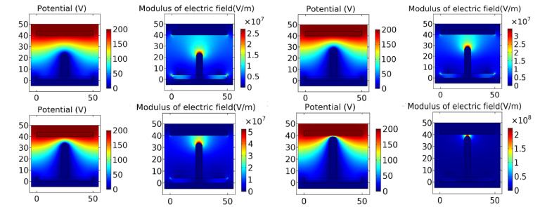
Electric potential and electric field intensity at different distances.
The software was used to simulate the potential distribution and electric field intensity distribution in the air at a distance of 25 μm, 20 μm, 15 μm, 10 μm, and 5 μm between the individual carbon nanotube fibers and the anode metal plate at the same voltage (Fig. 3), and the voltage of 200 V was taken. Finally, the simulation results are compared and analyzed.
The simulation results show that the potential distribution between the emitter and the anode is compressed due to the presence of carbon nanotubes, and the electric field strength increase as the gap distance decreases. At a distance of 25 μm, the maximum value of the electric field are concentrated only on the tip. As the gap distance decreases, the maximum electric field strength value of the region gradually extends to the anode until the carbon nanotubes are joined to the end plates to form a “path” of maximum electric field strength.
In order to verify the influence of the distance between the emitter and the anode plate on the field emission, the field emission properties of the carbon nanomaterials were further investigated. A field emission experimental platform for carbon nanomaterials was established. The key components of the experimental platform include observation platform, detection platform, MPC-200 micro manipulator, and the dual channel system digital source tables.
In this experiment, TNF300 type carbon nanotube fiber is used as cathode emission material, and the diameter is about 66 μm. The operation was simple and easy to observe. The dual channel system digital source table has over-current protection device, which can avoid the resulting breakdown of the damage to the instrument and the experimental materials.
The real-time image under the microscope can be transmitted to the computer through the data line. Moreover, the parameters of light source brightness and white balance can be adjusted so as to observe the experimental process at the computer end and adjust the distance between the materials. MPC-200 micro manipulator can achieve precise adjustment of micron distance between two probes, which can avoid the error of manual operation. Besides, the controller can move to the computer and adjust the distance using the remote control of the digital camera. This will help the experiment to be simple and stable.
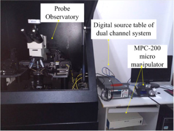
The experimental instrument.
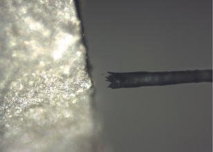
Imaging of carbon nanotube fibers and anodes under a microscope.
To start the experiment, connecting the high side of the source meter to the anode and the low side of the source meter to the carbon nanotube tip. The cathode and the anode are placed under a microscope, and the distance between the anode material and the carbon nanotube fibers is changed by adjusting the micro-manipulator. The field emission current curves of carbon nanotube fibers at different distances of voltage ranging from 0 to 200 v are measured by using the digital source meter. The experimental conditions are changed to further explore the factors affecting the field emission properties of carbon nano-materials. Since the experiments are carried out in the air, instead of vacuum conditions, not every experiment guarantee the meaningful results.
After many experimental tests of different anode and carbon nanotube distance, we obtained many sets of experimented results. The corresponding current and voltage values are input into the software to obtain the volt ampere characteristic curve; we selected three representatives of the experimental result.
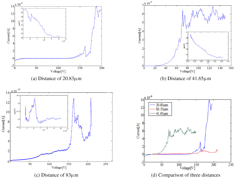
Field emission voltammetry characteristics and the F-N curve.
The distance between the carbon nanotube fiber tip and the anode metal plate was changed to 83.3 μm, and the voltage was gradually increased from 0 to 200 V. According to the volt-ampere characteristic curve, as the voltage increases, the current value begins to rise slowly, and when the voltage reaches 170 V, the current change rate reaches a maximum value. The experiment yielded a current value of approximately 0.5 nA.
The experimental data of voltage and current are processed in Excel, take 1/V as the abscissa, and ln (I/V2) as the ordinate. The field emission F-N curve is obtained by remapping in MATLAB.
It can be seen from Fig. C that the F-N curve is not linear, it does not conform to the classic F-N tunneling theory, indicating that there is no field emission in the current distance and voltage conditions, it is necessary to reduce the distance between the top and the anode plate and redo the experiment.
The distance between the carbon nanotube fiber tip and the anode metal plate was changed to 41.65 μm. According to the volt-ampere characteristic curve, when the voltage is about 130 V, the current change rate reaches a maximum value; when the voltage reaches 200 V, the current reaches about 2 nA. In addition, the field emission turn-on voltage value is reduced by about 40 V when the distance is 83.3 μm, and the current value is increased by an order of magnitude.
Reprocessing the data and making the FN curve, we found that when 1/V is less than 0.05, the FN curve is almost a straight line at a voltage greater than 125 V, which is consistent with the curve described by FN theory. It also shows good performance in this range. The corresponding field emission turn-on voltage is 124 V.
When the distance between the emitter tip and the anode metal plate is adjusted to 20.825 μm, the resulting emission current will reach 10 nA. The peak of the emission current obtained by the experiment was increased by an order of magnitude with respect to the result at 41.65 μm.
By processing the experimental data again and plotting the FN curve, it was found that in this case, although the distance between the tip of the nanotube and the anode was reduced, the resulting field emission FN curve did not become smoother but became fluctuating. This indicates that the experimental effect of field emission does not always increase as the tip-to-anode distance becomes smaller. And in many experiments, there is a fact that, because the distance is too short, the tip of the carbon fiber burns during the process of increasing the voltage from 0 to 200 V. Therefore, it can be concluded that when the field emission experiment is performed in the air, if the emission distance is too short, the effect of the field emission effect is affected.
According to the field emission characteristics of carbon nano-materials, a new non-contact discharge method in the air is proposed. Through software simulation and experimental analysis, we find that when the distance between the anode and cathode is 41.65 μm, the field emission turn-on voltage is lower than the voltage at other distances. When the voltage reaches 70 V, the emission current can reach about 6 nA. The FN curve obtained by processing the experimental data is closer to a straight line, which proves that the emission effect is better. Increasing or decreasing the distance will result in a weaker field emission effect. Since the experimental environment is in the air, which is different from the vacuum conditions in the field emission experiments mentioned in other papers, it can be said that this paper has important reference value for solving the bearing current problem.
Footnotes
Acknowledgements
This work was supported by National Natural Science Foundation of China (No. 51577122).